HAL Id: hal-01241131
https://hal-enpc.archives-ouvertes.fr/hal-01241131
Submitted on 15 Jan 2016
HAL is a multi-disciplinary open access
archive for the deposit and dissemination of sci-entific research documents, whether they are pub-lished or not. The documents may come from teaching and research institutions in France or abroad, or from public or private research centers.
L’archive ouverte pluridisciplinaire HAL, est destinée au dépôt et à la diffusion de documents scientifiques de niveau recherche, publiés ou non, émanant des établissements d’enseignement et de recherche français ou étrangers, des laboratoires publics ou privés.
Thermal and chemical effects in shear and compaction
bands
Jean Sulem, Ioannis Stefanou
To cite this version:
Jean Sulem, Ioannis Stefanou. Thermal and chemical effects in shear and compaction bands. Geome-chanics for Energy and the Environment, Elsevier, 2015, �10.1016/j.gete.2015.12.004�. �hal-01241131�
1 Thermal and chemical effects in shear and compaction bands
Jean Sulem, Ioannis Stefanou
Université Paris-Est, Laboratoire Navier, Ecole des Ponts ParisTech, Marne-la-Vallée, France
Abstract
Strain localization zones in the form of shear bands or compaction bands in geomaterials are observed across scales from sub-millimetric (grain size) to kilometric scale (geological structures). Triggering and evolution of such narrow zones of localized deformation depends on many factors. The mechanical behavior of geomaterials is central for the formation of such zones. However, thermal, pore-pressure and chemical effects play a crucial role in shear and compaction banding. Temperature increase and activation of chemical reactions such as mineral dehydration, carbonate decomposition, as well as dissolution/precipitation control the triggering and the evolution of localized deformation zones. Moreover, the inherent heterogeneous microstructure of geomaterials plays a significant role during strain localization. The purpose of this paper is to provide a review of recent research regarding the effects of temperature, pore-pressure, chemical reactions and microstructure on strain localization in geomaterials. Examples have been taken in relation with seismic slip and with compaction banding. Strain localization is treated as an instability from a homogeneous deformation state. Different types of instabilities may (co-) exist depending on different multi-physical couplings and micro-mechanisms. Finally, a comparison of rate dependent Cauchy continuum and rate independent generalized continua (Cosserat continuum) is made, which leads to an analog expression for the critical perturbation wave length, which scales the thickness of the localized zone and defines the region that non-homogeneous deformations are possible.
Key words: Deformation bands; strain localization; thermo-hydro-chemo-mechanical
2
1 Introduction
Deformation zones in the form of shear bands or compaction bands in geomaterials are observed on a very large range of scales from sub-millimetric (grain size) to kilometric scale (geological structure). Strain localization refers to physical processes that control the bifurcation of a deforming body from a previously homogeneous deformation to a point for which critical conditions are met for the deformation pattern to drastically change into a highly localized deformation band. This heterogeneity of deformation is associated with an induced heterogeneity of strength and of other material properties (e.g. porosity, grain size, pore size, permeability…) in relation with the transformation at the micro-scale of the microstructure of the rock inside the band.
Failure of many engineering structures is characterized by the formation and propagation of shear bands. Shear zones play also a major role in the nucleation of earthquakes, landslides and slope failure. They also are of prime importance in the flow of water, gas and oil in the subsurface as they can serve as conduits or barriers for fluid and heat fluxes. On the other hand, the formation of compaction bands corresponds to failure zones in the direction perpendicular to the major principal stress. They indicate a transition between brittle failure and cataclastic failure. The presence of compaction bands in nature may provide useful information on various geological processes as it is an indication of the stress state history of a geological formation. Compaction bands are usually characterized by a significant reduction of the pore space, which in most cases is accompanied by an important reduction in permeability (Olsson, Holcomb, & Rudnicki, 2002). Their presence can lead to largely anisotropic flow in fluid infiltrated porous rocks. Therefore, compaction bands are also of primary importance in reservoir mechanics for hydrocarbons production, CO2 storage and
mineral exploration.
Although strain localization in the form of shear band formation can occur with negative or positive rate of strain hardening, the latter being possible for deformation states close to plane strain (Rudnicki & Rice, 1975), softening behavior definitely favors shear banding. This softening behavior may correspond to a mechanical degradation of the rock properties (microcracking, grain crushing and grain size reduction…) (Das, Nguyen, & Einav, 2011), but various other physical processes can be responsible for it (Regenauer-lieb et al., 2013). The effect of an infiltrated pore fluid which interacts with a rock mass can lead to a hardening or softening behavior depending on the volumetric response of the rock (dilatant or contractant). The effect rapid heating of a saturated geomaterial leads to pore-fluid pressurization due to
3
the discrepancy between the thermal expansion of water and solid grains. Thermal pressurization is a softening mechanism as it results in a decrease of the effective mean stress and thus of the shear strength. Chemical reactions such as dissolution/precipitation, mineral transformation at high temperature (dehydration of minerals, decomposition of carbonates, …) affect the solid phase of the rock, sometimes release a new fluid phase in the system (dehydration reactions) and can induce a positive feedback in the progressive mechanical degradation. On the other hand, mechanical damage increases the reaction surface between the reactive fluid and the solid and enhances dissolution and further material weakening (Hu and Hueckel 2007).
A key parameter when studying multi-physics effects on the formation and evolution of deformation bands is the actual width of the localized zone. Obviously, this parameter plays a major role in the energy budget of the system as it controls the feedback of the dissipative terms in the energy balance equation. As emphasized by (Rice et al. 2014) narrow deforming zones concentrate the frictional heating, which leads to large temperature rises and thus to more rapid weakening. The width of the deforming zone is determined by the various physical processes involved in the weakening mechanisms but it also controls the multi-physics couplings which occur during dynamic slip.
It is well known that strain localization analyses performed for rate-independent materials within the frame of classical continuum theories lead to infinitesimally narrow localized zone. This reflects the ill-posedness of the underlying mathematical problem and can be traced to the absence of a material length in the constitutive equations. Viscous regularization by considering strain rate hardening is commonly considered to overcome this problem. Another approach is to resort to continuum models with microstructure to describe on a more physical basis the localization phenomena. These generalized continua usually contain additional kinematical degrees of freedom (Cosserat continuum) and/or higher deformation gradients (higher grade continuum). They introduce material internal lengths and also characteristic time scales. The internal length and the micro-inertia introduced from generalized continua permit to describe localization phenomena in zones of finite thickness and lead to a finite evolution rate of a deformation band like in strain rate dependent constitutive laws (Veveakis et al. 2013; Sulem et al. 2011; Veveakis et al. 2012).
In this paper, we review some multi-physics couplings, which enhance strain localization in geomaterials. The first part of the paper focusses on shear banding, emphasizing thermal and chemical effects in relation with shear heating. As mentioned above the localization zone
4
thickness can be captured either by considering rate dependency of the constitutive law or by resorting to higher order continua that possess an internal length. In order to explore the link between the two different modeling approaches a comparison between a) rate dependent Cauchy continuum and b) rate independent Cosserat continuum is shown for the scaling of the localized zone thickness. The comparison is made on the base of a simplified example in order to illustrate the main differences and aspects of each modeling strategy. The last part of the paper is focused on compaction band formation in porous materials triggered by dissolution as an example of another type of chemomechanically induced strain localization.
2 Thermo-chemo-chemical couplings and stability of shear zones
2.1 Problem statementWe consider a layer of saturated rock with thickness D deformed in shear at a slip rate V (Figure 1). Several investigations have shown that the ultracataclastic gouge zones forming the fault core have a much lower permeability (< 10-19 m2) than that in the surrounding damage zone (e.g. Wibberley and Shimamoto, 2003, Sulem et al., 2004). Therefore, as fluids and heat are trapped inside the slip zone during an earthquake, it is interesting to investigate the stability of undrained adiabatic shearing of such a gouge layer. This is done by assuming that drainage and heat flux are prohibited at the boundaries of the layer. It is also assumed that the normal stress n acting on the layer is constant.
5 Figure 1. Model of a fault zone as an infinite layer under uniform shear strain rate V
D
.
In this 1D-model the velocity components, u1(x2, t), and u2(x2, t) in the direction parallel and normal to the fault respectively depend only on the time since the onset of slip and on the position x2 in the direction normal to the band. Inside such a shear-band the pore pressure p and the temperature T are assumed to be functions only of time t and of the position x2 in the direction normal to the band.
The governing equations of the system are the balance laws of linear momentum, mass and energy. Neglecting inertia effects (Rice, 2006), mechanical equilibrium leads to shear and normal stress which do not depend on x2.
12 22 2 2 0 , 0 x x (1)
The fluid mass balance equation (equation (2)) is the sum of three terms: the diffusion term, the thermal pressurization term and the term corresponding to the effect on pore pressure of inelastic porosity change (for example dilatancy). Chemical effects and their impact on the localization zone will be discussed later in the paper.
2 2 * 2 1 p hy p p T n c t x t t (2)
In equation (2), chy is the hydraulic diffusivity, * is the storage capacity, np tis the rate of inelastic porosity change, n
f n
/*is the undrained thermal pressurization coefficient, where f is the pore fluid thermal expansion coefficient and n is the thermal expansion coefficient of the pore volume, and n is the porosity of the rock. Typical values for range from 0.1 to 1MPa/°C (Ghabezloo and Sulem 2008).The energy balance equation (equation (3)) is the sum of two terms: the diffusion term and the source term corresponding to the frictional heat.
6 2 0 2 2 1 p th T T c t x C (3)
In equation (3), cth is the thermal conductivity, C is the specific heat, 0
p
is the plastic work which is assumed to be entirely converted into heat. The shear stress is proportional to the effective Terzaghi stress: f
n p0
where f is the friction coefficient.Considering that the layer is homogeneous and uniformly sheared at a constant strain rate
0 V D/
where V is the imposed slip rate, pore pressure and temperature are independent of
x2. A closed form solution for their evolution in time has been given by Lachenbruch (1980; see also Rice 2006; Sulem et al. 2007):
0 0 0 0 1 exp , with 1 exp n n Vt p p p L C h L f p Vt T T L (4)The pore-pressure increases towards the imposed normal stress n and the temperature increases towards T T0
n p0
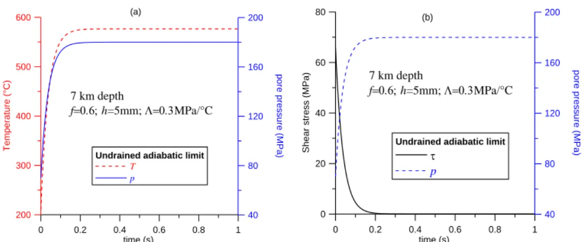
/. In due course of the shear heating and fluid pressurization process, the shear strength is reduced towards zero. We observe that the length scale L, which controls the shear stress evolution, is the same as the one which controls the temperature evolution. 0 0.2 0.4 0.6 0.8 1 time (s) 200 300 400 500 600 T e m p e ra tu re ( °C ) 40 80 120 160 200 p o re p re s s u re ( M P a )Undrained adiabatic limit
T p 7 km depth fh=5mm; MPa/°C (a) 0 0.2 0.4time (s)0.6 0.8 1 0 20 40 60 80 S h e a r s tr e s s ( M P a ) 40 80 120 160 200 p o re p re s s u re ( M P a )
Undrained adiabatic limit
p
7 km depth
fh=5mm; MPa/°C
(b)
Figure 2. Homogeneous layer at 7 km depth (T0210 C, p070MPa, n 180MPa), uniformly sheared at a constant strain rate (imposed slip velocity V = 1m/s) under locally undrained and adiabatic conditions.
7 2.2 Stability of adiabatic undrained shear
The stability of the above undrained adiabatic (uniform) solution can be studied by performing a linear perturbation analysis. Details of such an analysis are found in the paper of Rice et al. (2014); see also Sulem et al. (2011). Note that when performing this stability analysis, spatially-dependent perturbations are considered inside the layer so that heat and fluid diffusion is allowed inside the layer, whereas zero heat and fluid fluxes are imposed at the boundaries of the layer. If we assume constant friction coefficient, this solution is unstable for all wave lengths of the perturbation. Therefore, strain will localize into a zone of zero thickness, which corresponds to the solution of slip on a plane given by Rice (2006) for which the temperature rise is T
1 chy cth
n p0
. Considering the very low permeability of the fault gouge, chy and cth are of the same order of magnitude so that the temperature is in that case about twice bigger than the undrained adiabatic uniform solution. As mentioned in the introduction, the infinitesimally thin localized zone is reflecting the lack of a material length in the model (for example the grain size) that will act as a localization limiter. Rice et al. (2014) have considered a rate-dependent friction coefficient derived from rate-and-state friction (RSF) laws which are commonly used in seismology (Dieterich, 1979),
0 log 0
f f a , where a is a strain rate-hardening (or softening) parameter and it depends on temperature . Under temperature increase, a is not monotonous and experimental evidence shows that either thermal softening or thermal hardening takes place (Chester & Higgs, 1992; Scholz, 1998). This coupling is important as it plays a direct role on the stability of faults and of course on localization (Alevizos, Poulet, & Veveakis, 2014; Poulet, Veveakis, Regenauer-Lieb, & Yuen, 2014; Veveakis, Poulet, & Alevizos, 2014). The choice of the RSF law depends on the available experimental data and its mathematical form can lead to differences regarding temperature increase (Veveakis, Alevizos, & Vardoulakis, 2010). As it will be shown in the next paragraphs, temperature increase and strain localization are key factors as far it concerns the interplay between mechanics, heat and pore-pressure diffusion and the activation of chemical reactions induced by frictional heating.
Neglecting the direct effect of temperature increase on the RSF law, Rice et al. (2014) have obtained that for strain-rate softening (a < 0), the uniform solution of undrained adiabatic shearing is unstable for all wave lengths of the perturbation. For strain-rate hardening (a > 0),
8
only shear zones with a thickness h smaller than a critical value
0 0 2 0 th hy cr c c a C h f f a can support stable homogeneous deformation. This critical thickness is interpreted as the thickness of the localized shear zone and this statement was corroborated by numerical simulation in the post-localization regime performed by (Platt, Rudnicki, & Rice, 2014). Interestingly, this expression of the critical shear zone thickness exhibits two competing processes: Fluid and thermal diffusion and rate-dependent frictional strengthening tend to expand the localized zone, while thermal pressurization tends to narrow it. As emphasized above, strain localization in a narrow zone leads to faster and stronger temperature rise than that predicted if localization is ignored.
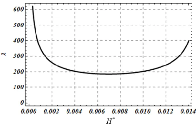
For representative values of the material parameters, stress and temperature conditions of a fault at a seismogenic depth of 7 km, Rice et al. (2014) have obtained typical values of few microns to few tens of microns for the thickness of the localized zone. This value is comparable to the gouge grain size and therefore it might be important to take into account the granular microstructure of the material. This has been proposed by Sulem et al. (2011) which studied localization in a fluid-saturated material accounting for the motion of individual grains using a Cosserat microstructure. In a Cosserat continuum, each material point possesses additional rotational degrees of freedom so that a rolling resistance is attributed to the grains. Note that an internal length R related to the grain size of the material is introduced in the formulation of constitutive laws for a Cosserat material. A stability analysis of undrained adiabatic shearing of an elastoplastic layer with strain hardening and dilatancy has been proposed. It was shown that instability can occur even in the hardening regime of the underlying drained stress-strain response if dilatant hardening cannot compensate the thermal pressurization of the pore fluid. A remarkable result is that if we do not take into account the effect of microstructure and the associated micro-inertia, the underlying mathematical problem is ill-posed, i.e. for a hardening modulus lower than the critical hardening modulus at instability, the growth coefficient in time of the instability is infinite. The complete dynamic analysis for a Cosserat continuum shows that the growth coefficient of the instability is always finite and that it depends on the wavelength of the instability mode. The wavelength of the instability mode for which the growth coefficient is maximum will evolve faster and it will dominate the others. This selected wavelength is depicted in Figure 3. For representative values of a fault zone at 7 km depth, it was found that the selected wave length is about 200R. The localized zone thickness is half of this value, so
9
that for typical values of a grain size of few microns for the fault gouge, this corresponds to a shear band thickness of few hundreds of microns which is compatible with field observations in fault zones. In the next paragraph it will be shown how the thickness becomes even smaller if mineral decomposition reactions take place.
Figure 3. Wave length selection: is the wave length of the perturbation normalized by the Cosserat internal length R, H* is the strain hardening modulus of the elastoplastic model.
2.3 Effect of chemical reactions induced by frictional heating
In addition to thermo-hydro-mechanical (THM) couplings, the effect of chemical reactions that are triggered due to shear heating and temperature increase, may induce additional weakening mechanisms. The ubiquitous presence of clay and hydrous phyllosilicates along major subsurface fault zones has been reported in many recent studies (e.g. Sulem et al. 2004; Solum et al. 2006; Hirono et al. 2008). These minerals are thermally unstable and can release adsorbed and/or structural water while turning into a denser reaction product. In addition to these dehydration reactions, thermal decomposition of carbonates, which are present in every fault zone, from the ductile-brittle transition (~ 15 km) to the subsurface, has also been reported during rapid slip (e.g. Famin et al. 2008; Rowe et al. 2012; Colletini et al. 2014). Carbonates are present in many seismically active regions worldwide, where main shocks and aftershocks nucleate within and propagate through thick sequences of carbonates (Italy, e.g. 2009 Mw 6.3 L’Aquila earthquake). Breakdown of carbonate minerals creates sudden localized spikes in CO2 pressure, driving local overpressure and reducing fault-plane effective
stress (e.g. Sulem and Famin 2009). In addition, experiments show that carbonate dissociation produces nanoparticles facilitating nanopowder lubrication of the experimental faults (De
10
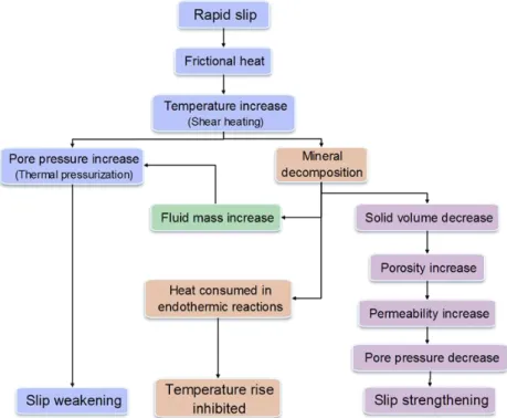
Paola et al., 2011). These chemical reactions are endothermic so that part of the frictional heat is actually consumed into the mineral decomposition. A schematic representation of coupled chemo-thermo-hydro-mechanical processes during seismic slip is shown in Fig. 4.
Figure 4. Schematic representation of coupled processes during seismic slip.
On the other hand, there is evidence that CO2 release as observed in crustal faults, active
and/or exhumed, coincides with seismic slip. Sato and Takahashi (1997) also reported that the HCO3‾ concentration increased by 30 wt% in springs located near the Nojima fault (Japan) immediately after the 1995 Kobe earthquake. This carbon discharge, together with other co-seismic geochemical anomalies, decreased gradually to normal values in the following ten months. A micro-infrared analysis of exhumed pseudotachylites (i.e. friction induced melts produced by seismic slip) from the Nojima fault revealed a carbon supersaturation in the melts. Moreover, the quantity of CO2 released by friction melting during the 1995 Kobe
earthquake was evaluated to 1.8 to 3.4×10³
tons (Famin et al. 2008). It is important to emphasize that the carbon had a biogenic isotopic signature both in springs and in the fault rocks, and did not correspond to carbon dioxide degassing from the mantle. Sulem and Famin (2009) have proposed the first theoretical study on the mechanical effect of calcite thermal decomposition (CaCO (calcite)3 CaO (lime) + CO (carbon dioxyde)2 ) on a fault layer of given thickness during seismic slip. The governing equations of the pore pressure and the
11
temperature evolution are formally the same as those given above (equations (2) and (3)). The effect of porosity change due to the solid decomposition on the permeability has been accounted for assuming a Carman Kozeny porosity-permeability relationship. Typical results are shown in Figure 5: (i) The endothermic chemical reaction limits the co-seismic temperature rise to a value which is controlled by the reaction kinetics; (ii) pore pressure increase is first due to thermal pressurization and then accelerates at the onset of the reaction up to a maximum and then decreases due to the reduction of solid volume and of the fluid diffusion process (pore pressure pulse). This results in a dynamic initial weakening of the shear strength followed by a re-strengthening.
0 1 2 3 4 time (s) 200 400 600 800 T e m p e ra tu re ( °C ) 60 80 100 120 140 160 180 p o re p re s s u re ( M P a ) T p 7 km depth fkf0=10 -19m2 h=5mm 0 1 time (s)2 3 4 2 4 6 8 10 12 S h e a r s tr e s s ( M P a ) 60 80 100 120 140 160 p o re p re s s u re ( M P a ) p 7 km depth fkf0=10-19m2 h=5mm
Figure 5. Effect of thermal decomposition of calcite on a homogeneous layer at 7 km depth (T0210 C, p0 70MPa, n180MPa), uniformly sheared at a constant strain rate
(imposed slip velocity V = 1m/s).
In these computations, the initial permeability of the slip zone was assumed to be as low as
19 2
10 m . The friction coefficient was taken equal to 0.1 in accordance with high velocity friction experiments that show that during coseismic slip the friction coefficient is low (Di Toro et al. 2004, 2011). In Figure 6, we compare the results of these computations to the case where thermal decomposition of carbonates is not included. The different response is clearly seen after about 1s when the temperature at which the chemical reaction is triggered is reached.
12 0 1 2 3 4 5 time (s) 0 400 800 1200 1600 2000 T e m p e ra tu re ( °C ) T without decarbonation T with decarbonation 7 km depth f kf0=10 -19m2 h=5mm 0 1 2time (s)3 4 5 60 80 100 120 140 160 180 P o re p re s s u re ( M P a ) p without decarbonation p with decarbonation 7 km depth f kf0=10-19m2 h=5mm
Figure 6. Effect of thermal decomposition of calcite on a homogeneous layer at 7 km depth : Evolution in time of temperature and pressure with and without mineral decomposition effect.
The observation that endothermic chemical reactions might buffer the temperature of fault zones during seismic slip leads to the conclusion that the activation of other weakening mechanisms such as melt lubrication might be inhibited. High Temperature rise limitation by thermal decomposition would provide another explanation to the notorious absence of positive heat flow anomaly on active crustal faults such as San Andreas (Lachenbruch and Sass, 1980): a large part of the heat produced by friction would be consumed by endothermic reactions.
The linear stability analysis of a layer under uniform shear in undrained adiabatic conditions presented in the previous section has been extended to account for chemical effects (Veveakis, Sulem, & Stefanou, 2012). It was shown that for a material with Cosserat microstructure, the thickness of the localized shear zone is first controlled by thermal pressurization of the pore fluid but then is reduced to a value close to 4-5R when the temperature of the slipping zone reaches the critical temperature of mineral decomposition (Figure 7). Similar conclusions was obtained by (Platt, Brantut, & Rice, 2015) for a rate dependent friction model.
13 Figure 7. Selected wavelength λ as a function of the chemical reaction activation temperature, Tc, and the
pre-exponential factor, A0, of the kinetics of the reaction, a parameter that may vary significantly, obtaining for
calcite decomposition values between 102 s−1 and 1020 s−1 (L’Vov et al. 2002).
Interesting observations on strain localization and dynamic weakening in calcite fault gouge have been reported in a recent paper of Smith et al. (2015). On the basis of high velocity rotary shear experiments, these authors have observed a shear band of 100 µm wide at peak stress and the nucleation of micro-slip surfaces to be dispersed in the shear band in the weakening regime. By the end of dynamic weakening, strain is localized to a single 2-3 µm wide principal slip surface. Similar observations have also been made by Han et al. (2010). Shear heating, thermal pressurization and thermal decomposition of carbonates are weakening mechanisms that can also explain large landslides. The Heart Mountain landslide of northwest Wyoming is the largest known sub-aerial landslide on Earth. This Eocene age landslide covers more than 3000 km2 with a very long runoff distance of more than 45 km (Hauge, 1993). An intriguing question is how such a massive volume of rock could have moved across a basal surface with an average regional dip of only 2°. Field observations and experiments on rocks taken from the landslide have shown that since the shear zone of the Heart Mountain slide is located within a dolomite layer, thermal decomposition and release of CO2 induced by
flash heating occurs, allowing a huge upper plate rock to slide over a ‘cushion’ of pressurized material (Goren et al. 2010, Mitchell et al. 2015).
14 2.4 Chemical weakening and earthquake nucleation
An interesting situation corresponds to shear localization in a chemically weakening material. This case is relevant for understanding the nucleation of intermediate and deep earthquakes within subduction zones. As discussed by Green (2007), deep earthquakes have been a paradox since their discovery in the 1920s. The combined increase of pressure and temperature with depth precludes brittle failure or frictional sliding beyond a few tens of kilometers. Nevertheless, earthquakes still occur in subduction zones to 700 km. Growing evidence suggests that the great majority of subduction zone earthquakes shallower than 400 km are initiated by breakdown of hydrous phases and that deeper ones probably initiate as a shearing instability associated with breakdown of metastable olivine to its higher-pressure polymorphs. Reaction weakening behavior has been extensively documented in the case of rocks containing dehydrating minerals such as gypsum and serpentinite. In the case of serpentinite dehydration, the reaction products may be weaker. This is the case for the dehydration of lizardite for which the produced ultra-fine grained olivine is weaker than the serpentinite aggregates (Rutter & Brodie, 1988):
2 2 5 4 10 4 3 4 3 2 2 olivine lizardite talc
5 MgSi O(OH) MgSi O (OH) 6 Mg SiO 9 H O
(R1)
This leads to a self-lubrication of the fault by the newly formed material. The intrinsic reaction-weakening process assumed here is thus an interesting possibility for dehydration-induced earthquakes at intermediate depths. Brantut and Sulem (2012) have assumed a simple evolution law for the friction coefficient f in order to describe chemical weakening during dehydration:
0 ln / 0
f f a b (5)
0
f is a reference friction coefficient for a reference strain rate 0 and a and b are positive constitutive parameters. This friction law is similar to the commonly used RSF laws where the ‘state’ is identified as the reaction extent .
The reaction rate is assumed to be of first order, which accounts for temperature dependency following an Arrhenius law and depletion:
15 (1 ) exp Ea A t RT (6)
where A is an pre-exponential factor, Ea is the activation energy of the reaction and R is the gas constant. It is shown that due to the endothermic character of the mineral decomposition reaction, the temperature is buffered during the reaction to a value close to the critical temperature Tc at which the reaction is triggered (Brantut, Sulem, & Schubnel, 2011; Sulem &
Famin, 2009). Therefore, the reaction rate can be linearized above Tc:
0 if if c T c c T T c T T c T T t (7)The pore pressure evolution is given by the fluid mass balance (Brantut et al., 2011; Sulem & Famin, 2009): 2 2 * 1 hy w f p p T c m t y t t (8)
where p is the pore pressure in the layer, is the undrained thermal pressurization coefficient (Rice, 2006), f is the pore fluid density, * is the elastic storage capacity of the rock, chy is the hydraulic diffusivity, mw is the mass of water that is released due to the reaction per unit of rock volume and is the ratio of pore volume creation to fluid volume release due to the dehydration reaction.
The temperature evolution is given by the energy balance equation. Heat is generated by dissipation of the frictional energy (shear heating), and is partitioned into temperature change and diffusion and reaction enthalpy, which is a heat sink for endothermic reactions. Denoting
0
m the mass of reacting mineral per unit of total rock volume and H the reaction enthalpy, we obtain (Brantut et al., 2011; Sulem & Famin, 2009)
2 0 2 th T T H c m t y C C t (9)
where is the applied shear stress on the fault, is the strain rate, Cis the specific heat per unit volume of the rock and c is the heat diffusivity. th
16
The linear stability analysis of the above system of equations has been performed by Brantut and Sulem (2012) and they have obtained the following expression for the critical wavelength (smallest wave length for which the growth coefficient of the instability is positive), below which all perturbations vanish in time:
0 0 2 ch th cr T c ac C b c (10)
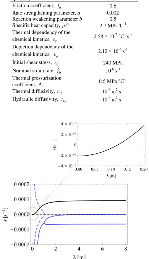
This value corresponds to the smallest wave length for which the growth coefficient of the instability is positive. We observe that it depends only on the thermo-chemical parameters and that it is not influenced by the pore pressure effect. We recall that if the chemical reaction is In order to illustrate this analysis, we use the parameter values given in Table 2. They are taken from Brantut & Sulem (2012) for lizardite dehydration of a layer at 30 km depth, which is sheared at a very low strain rate of 10-6 s-1. In Figure 8, the growth coefficient s of the instability mode is plotted in terms of the perturbation wave length. The smallest wave length for which s becomes positive is given by equation (10).
It is worth investigating the evolution of the localization zone in a simple case of a gouge layer of 5 m thickness. An initial small perturbation of the shear strain field is imposed with a wavelength equal to the gouge thickness. According to Figure 8, this wave length is unstable. In particular, the critical wave length given by (10) is 0.12 m (Figure 8).
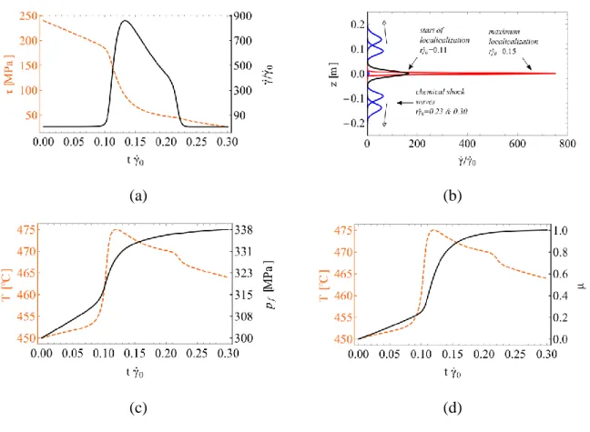
Figure 9a shows the evolution of the shear stress and of the shear strain rate in the middle of the localization zone. Figure 9b presents the profile of the shear strain at various time instants showing the localization and the de-localization process when the reaction is depleted. Note that in this example, a very low strain rate corresponding to a subducting slab was assumed. For this strain rate and due to partial dehydration (the material in the middle is depleted but not in the adjacent zones) chemical traveling waves are triggered and travel towards the boundaries of the gouge layer. Figure 9c depicts the temperature increase due to shearing in the middle of the shear band. It is worth mentioning that after a point the (endothermic) chemical reaction buffers the temperature rise. Figure 9d shows the evolution of the chemical reaction and the pore pressure increase in the middle of the shear band.
17
Table 1. Parameter values for lizardite dehydration at a depth of around 30 km (Brantut & Sulem, 2012).
Quantity Value
Friction coefficient, f 0 0.6
Rate strengthening parameter, a 0.002
Reaction weakening parameter b 0.5
Specific heat capacity, C 2.7 MPa°C-1
Thermal dependency of the
chemical kinetics, cT 2.58 × 10
-7
°C-1s-1 Depletion dependency of the
chemical kinetics, c 2.12 × 10
-6
s-1
Initial shear stress, 0 240 MPa
Nominal strain rate,
0 10-6 s-1Thermal pressurization
coefficient, 0.5 MPa °C
-1
Thermal diffusivity, c th 10-6 m2 s-1
Hydraulic diffusivity, chy 10-6 m2 s-1
Figure 8. Growth coefficient (Lyapunov exponent) in terms of perturbation wavelength. The real part is plotted in solid line and the imaginary part in dotted line. Black color signifies the mode related to chemical instability and blue the mode related to thermal pressurization (Re[s]<0 for this mode). One critical wavelength exists.
18
(a) (b)
(c) (d)
Figure 9. Strain localization due to chemical softening in a 5 m thick dehydrating gouge layer: (a) Shear stress drop in the middle of the shear band and shear strain evolution. The system localizes to a narrow band because of
dehydration, but then it delocalizes due to depletion; (b) Evolution of shear band localization – profile of shear strain rate; (c) Temperature and pore pressure increase in the middle of the shear band. The chemical reaction buffers temperature rise; (d) Evolution of the chemical reaction in the middle of the shear band. At t0 0.1 the
reaction effects become important and the material is rapidly depleted in the middle of the gouge (1) until
0 0.3
t . Due to partial depletion, chemical shock waves are triggered and travel towards the boundaries of the gouge.
19
3 Rate dependent models versus higher order continua: an illustrative
example
In this section the simple example of adiabatic shearing of a rock layer under constant shear stress is considered. The purpose of this example is to investigate and juxtapose two different modeling frameworks and compare the conditions for which shear band localization takes place in each case.
The first framework is the Cauchy continuum with rate dependent constitutive law (viscoplasticity). Rate dependent constitutive and in general viscoplastic constitutive law in the frame of Cauchy continuum are frequently used in the literature as they lead to finite thickness shear band formation. The relation between viscosity and shear band thickness (and consequently material length scale) has been discussed in several discussed in several publications (e.g. Wang, Sluys, & De Borst, 1996).
The second modeling framework is Cosserat elastoplasticity. Cosserat continumm (Cosserat & Cosserat, 1909) is a special case of higher order continua, which are also called generalized continua (for a classification of the most common higher order continua we refer to Godio et al. (2015)). Cauchy continuum is a special case of the Cosserat continuum if one neglects the additional rotational degrees of freedom that the latter has and their conjugate in energy generalized stresses.
Thermal softening is taken into account as a destabilizing mechanism that may lead to shear band localization. The complexity of the chosen constitutive laws and the multiphysical couplings considered is kept to a minimum in order to reveal the salient futures of each one of the aforementioned frameworks, their similarities and their differences. For a more detailed modeling in the frame of Cosserat continuum involving thermo-poro-chemo-mechanical couplings and more elaborate constitutive laws for the rock material, the reader is referred to Sulem et al. (2011) and Veveakis et al. (2012; 2013). In the same way, the reader is referred to Rice et al. and Platt et al. (2014; 2014) for the Cauchy rate dependent framework under thermo-poro-chemo-mechanical couplings as discussed in section 2.2.
The thickness of the layer considered is D and a constant normal and shear stress is applied at the boundaries of the layer as depicted in Figure 10. Initially, the layer is considered to be in a state of homogeneous shear deformation.
20 Figure 10. Shearing of a rock layer: Cosserat rotational degree of freedom ωand couple stresses.
In both models it is assumed that all the plastic work is converted to heat and that Fourier’s law is applicable. Under these assumptions, the heat equation, Eq.(3), is written in indicial notation as follows: 2 2 2 1 p 1 p th ij ij ij ij T T c m t x C C (11)
where, T T x t
2,
is the temperature inside the layer and ij ij
x t2,
, ijp ijp
x t2,
are respectively the generalized stress and plastic deformation rate tensors. A common assumption is to consider that the layer is invariant in the x and 1 x directions. Consequently 3the derivatives in these directions are zero.
Repeated indices indicate summation and i j, 1, 2,3. (.),i denotes derivation in the i direction, i.e. (.),i (.)
i
x
, and (.) is the time derivative. A small deformation framework is considered for this example and the slip event is sufficiently rapid in order to justify adiabatic conditions at the boundaries of the layer.
21 3.1 Cauchy continuum with rate dependent constitutive law
Let’s assume a simple rate dependent constitutive law for the shear stress at a point inside the shear layer:
12 0 H 12 T Ts
(12)
where H is a mechanical hardening parameter (positive), a thermal softening parameter (negative), T a reference temperature and s 0 the shear stress at steady state and reference temperature.
For a Cauchy continuum the linear momentum balance is:
, 0
ij j
(13)
Inertia terms and body forces are neglected in this example. The angular momentum balance imposes the symmetry of the stress tensor, ij ji. For a Cauchy continuum, ij ui j, , where u is the displacement in the i i direction.
At steady state T T Ts, 1212 0, 22 22 0, 12 12 0 and T0. This state will be stable as long as any perturbation does not grow in time. By perturbing the temperature and displacements fields at steady state (T TT, ui uiui) and by neglecting the higher order terms, Eqs. (11), (12) and (13) become:
12 12 12 22 2 2 2 12 12 2 2 0 ; 0 1 p p th H T x x T T c t x C (14)
The perturbations T, u should fulfill the boundary conditions of the rock layer. Equations i
(14) together with the boundary conditions
2 0 D z T z , 12 0 2 D z and
22 22 0 2 D z
form a linear system of partial differential equations which admits
solutions of the type:
2 sin 2 cos st i i st u U e z T Te z (15)
where s is the so-called growth coefficient and D
N , N 1, 2,3,... By replacing (15) into (14) we obtain: 2 0 2 4 cth s H C (16)
The system is unstable when s0 or, equivalently, when the wavelength of the perturbation is bigger than a critical wavelength rd
cr : 0 2 rd th cr Hc C (17)
This critical wave length will be compared with the one derived by the Cosserat continuum approach in the next section.
3.2 Cosserat elastoplasticity
Compared to the classical Cauchy continuum, Cosserat continuum is equipped with additional degrees of freedom, i.e. the Cosserat rotations. The rotational degrees of freedom are conjugate in energy with moments, the so-called couple stresses. For a Cosserat continuum, the linear momentum balance leads to:
, 0
ij j
(18)
23
, 0
ij j ijk kj
m (19)
Body forces and moments as well as inertia and micro-inertia terms are also neglected in this paragraph. It is worth mentioning that due to the presence of moments the stress tensor is not symmetric, i.e. ij ji. The generalized strains of the Cosserat continuum are
,
c ij ui j ijk k
and the curvatures are ij i j, .
An elastic perfectly plastic constitutive behavior with thermal softening is assumed in this example. More advanced Cosserat constitutive models such as the Mühlhaus-Vardoulakis Cosserat plasticity model (Mühlhaus & Vardoulakis, 1987; Papanicolopulos & Veveakis, 2011; Vardoulakis & Sulem, 1995) might be used, but the advantage of this simple model is that analytical derivations can be performed, which permits a convenient comparison with the above rate dependent model. By analogy with the Cauchy rate dependent model presented in the previous paragraph, the yield surface is defined as:
(12) 0 s 0
F TT (20)
where ( )ij denotes the symmetric part of the stress tensor. In this way the same shear stress limit and thermal softening with the Cauchy model is retrieved if one neglects the rate dependent term in Eq.(12). The strains and curvatures of the Cosserat medium are split in elastic and plastic parts:
el pl ij ij ij el pl ij ij ij (21)
Nevertheless, because of the chosen yield surface (Eq.(20)) the plastic curvatures are zero and therefore they do not contribute to the heat equation (Eq.(11)). In a centrosymmetric, linear elastic isotropic Cosserat medium, the stresses are related to the generalized elastic deformation measures according to the following constitutive relations (Vardoulakis, 2009):
24
( ) 1 [ ] 2 2 ( ) 2 3 [ ] 1 2 2 3 4 4 el el el el ij kk ij ij kk ij ij el el el ij ij ij kk ij K G G m GR GR (22)where K is the bulk modulus, G is the shear modulus, 1, 2, 3 are positive material constants and R is an internal length parameter, which here is identified to the mean radius of the grains of the Representative Volume Element (RVE). For more details on homogenization approaches tailored to Cosserat continuum and upscaling, both in elasticity and plasticity, the reader is referred to (Bardet & Vardoulakis, 2001; Godio, Stefanou, Sab, Sulem, & Sakji, 2015; Stefanou, Sulem, & Vardoulakis, 2008, 2010). ( )ij and [ ]ij denote respectively the symmetric and anti-symmetric part of ij. The Cosserat shear modulus, which expresses the stiffness related to the relative rotation of the particle (e.g. of a grain) with respect to the macro-rotation of the continuum (e.g. assemblage of grains) is defined as Gc 1G. As the system is invariant in x and 1 x directions the momentum balance equations become: 3
22 12 2 2 32 21 12 2 0 ; 0 0 x x m x (23)
At steady state we have a Cauchy continuum under homogeneous shear. In particular,
s
T TT , (12) (12) 0, [12][12] 0, m32 m32 0, 2222 0 and T 0. This state will be stable as long as any perturbation does not grow in time. By perturbing the temperature, the displacement and the rotation fields at steady state (T TT, ui ui ui,
3 3 3
c c c
) and by neglecting the higher order terms, Eqs.(11) and (23) give:
12 22 2 2 32 21 12 2 2 12 12 2 2 0 ; 0 0 2 p th x x m x T T c t x C (24)
25 [12] 12 21 32 [12] 2 32 2 2 4 c c G T G T R m G (25)
where it was taken 3 1 for simplicity. The perturbations T, u and i 3c
have to fulfill the boundary conditions of the rock layer:
2 0 D z T z , 12 0 2 D z , 22 0 2 D z and 32 0 2 D m z
. Eqs.(24) and (25) together with the above boundary conditions form a
linear system which admits solutions of the form:
3 3 2 sin 2 cos 2 cos st i i c st st u U e z e z T Te z (26)
where s is the growth coefficient, D
N , N1, 2,3,... and
4 2 2 2 2 2 2 2 0 16 4 8 th G R Cc s G R C R (27)where we set Gc G for simplicity.
The system is unstable when s0 or, equivalently when the wavelength of the perturbation is bigger than a critical wavelength Cos
cr :
2 2 0 0 0 2 2 2 Cos cr R GC R GC (28)For typical values of the shear modulus, the applied shear stress at the boundary, the thermal softening parameter and specific heat, it holds G C 0. The stability condition and the critical wavelength for the Cosserat elastoplastic medium are formally similar to the ones obtained for the Cauchy rate dependent medium.
26
Even though the models are based on different constitutive assumptions and micro-mechanisms, the resemblance of the expressions for the critical wavelength (Eqs.(28) and (17) ) impels an analogy between the hardening parameter of the viscoplastic model Hand the
Cosserat internal length, which here was chosen equal to the mean grain radius: 2
th
Hc R G.
The hardening parameter H can be measured experimentally for a given rock and it generally decreases during shearing together with the size of the grains and the shear modulus which also decrease due to the important shearing and comminution. It is worth mentioning that the term R G represents the rolling stiffness of the grains, which in comparison with the classical 2
Cauchy continuum, rigidifies the system, in the same way that the viscous term in the rate dependent friction law does. If we take the example of a highly granulated fault gouge with a
grain size of 10 μm and assuming a shear modulus G = 300 MPa, then for 2
1 mm s
th
c , the
hardening parameter H is equal to H 0.03 MPa s, which is in agreement with experimental measurements (Blanpied, Lockner, & Byerlee, 1995; Chester & Higgs, 1992).
Consistently, we observe that for rate dependent friction, localization in a zone of finite thickness is possible only when a mechanism of internal thermal diffusion is allowed. In other words if cth 0 then the system is always unstable (s0 in Eq.(16)) independently of the layer thickness. We thus observe the similar role of the diffusion length and of the Cosserat internal length in the control of the thickness of the localization zone.
27
4 Dissolution weakening and compaction banding
4.1 Multi-scale modelling of strong chemo-poro-mechanical coupling
In a recent paper (Stefanou & Sulem, 2014), instabilities in the form of compaction bands as triggered by chemical degradation of the solid skeleton have been studied. Chemical dissolution and grain breakage have been considered. The interest of the approach is in the strong chemo-poro-mechanical coupling which was considered. As the stresses and the deformations evolve, the grains of the material break leading to an increase of their specific surface. As the dissolution rate depends upon the area of contact between the reactive fluid and the minerals, dissolution is accelerated by grain fracturing and grain breakage and chemical softening is further enhanced.
The effect of chemical dissolution is important in field and in reservoir applications. For instance, the experimental results of Xie et al. (2011) showed that the chemical dissolution of a limestone leads to a significant increase of the porosity (from 23% for the intact rock to 27% for the degraded one). According to the same authors, the plastic pore collapse threshold is also reduced from about 30 to 20 MPa and the chemically degraded materials become more collapsible and more ductile due to the increase in porosity and the degradation of the inter-granular cementation. This evidence is corroborated by other authors (e.g. Nova et al., 2003; L.-B. B. Hu & Hueckel, 2007a; L.-B. Hu & Hueckel, 2007b; Buscarnera, 2012; Ciantia et al. 2014) for a class of geomaterials and results in a contraction of the elastic domain only due to chemical reasons (chemical softening). In parallel, in a saturated porous geomaterial, the progressive mechanical damage of the solid skeleton during compaction has as a result the increase of the interface area of the reactants (i.e. of the solution with the solid) and consequently the acceleration of the dissolution rate of the solid phase (Rimstidt & Barnes, 1980). Thus, the solid skeleton is degraded more rapidly (mass removal because of dissolution), the overall mechanical properties of the system diminish (contraction of the elastic domain – chemical softening), deformations increase and the solid skeleton is further damaged (intergranular fractures, debonding, breakage of the porous network etc.). Figure 11 schematically shows this positive feedback process, whose stability is not guaranteed. Notice that chemical softening is central for compaction banding in the absence of other softening mechanisms such as mechanical softening. Of course, reactions resulting to chemical hardening (e.g. Ulm & Coussy, 1996) do not lead to compaction banding.
28 Figure 11. Positive feedback process due to dissolution and solid skeleton damage (e.g. intergranular fracturing,
breakage of the porous network, matrix cracking, grain-matrix debonding etc.)
A two-scale approach was proposed as the reaction kinetics is considered at the micro-scale (grain level), whereas the balance and constitutive equations are written at the macro scale i.e. the RVE. Due to the existing heterogeneity of the microstructure (e.g. different grain sizes and constituents in the RVE) the dissolution rate may not be homogeneous over the RVE. The size of the RVE is a finite statistical quantity that depends upon the geomaterial at hand. The chemical softening rate of the yield surface is therefore related to the average, over the RVE, of the reaction rate at the grain level. This average procedure naturally introduces a characteristic length (size of the RVE). This approach is directly inspired from the development of non-local continuum theories. For heterogeneous materials, the constitutive law at a point of the continuum should involve weighted averages of a state variable over a certain neighborhood of that point. This leads to an integral type of constitutive equations. Along the same lines of thinking, gradient type constitutive models take into account the field in the vicinity of the considered point by enriching the local constitutive equations with higher order gradients of the deformation field (Germain, 1973; Vardoulakis & Sulem, 1995). As emphasized by Bazant & Jirásek (2002), resorting to nonlocal continuum appears to be an effective means for regularizing boundary value problems with strain softening. In our problem, the introduction of this ‘chemical’ characteristic length gives a length scale to the problem and naturally leads to a selection of a particular wave length when performing a linear stability analysis of the system. Details of the analysis can be found in the paper of
Solid skeleton mechanical damage Increase of effective specific area of reactants Acceleration of dissolution Chemical Softening
29
Stefanou & Sulem (2014). We just recall in the following the main assumptions and the principal results.
Micro-scale:
We consider a dissolution process of the form:
3 1 2
solid +solvent solution. For example the
dissolution/precipitation of quartz in water is described by the following chemical equation:
2 2 4 4
SiO (solid)+2H O(liquid) H SiO (aqueous solution) (R2)
Another example is the dissolution of calcite with water that is saturated with carbon dioxide:
3 2 3 3 2
CaCO (solid)+H CO (aqueous solution) Ca HCO (aqueous solution) (R3)
This equation represents a set of consecutive reactions that take place and are responsible for the dissolution of carbonate rocks (Grgic, 2011). The reaction kinetics is written in a simplified manner as:
2 2 2 1 eq w S w k t e w (29)
where w is the mass fraction of the dissolution product in the fluid, 2 k is a reaction rate coefficient, e is the void ratio, S is the specific surface of a single grain (which is inversely proportional to the grain size) and 2eq
w the mass fraction of dissolution product to the fluid mass at chemical equilibrium. It should be emphasized that Eq.(29) is written at the microscale and that w , 2 S and e represent local quantities, which are not necessarily homogeneous over the RVE. Grain crushing is also described at the micro-scale. We use here a simple empirical expression for the evolution of the grain size in terms of the mechanical work input as proposed by Lade et al. (1996):
0 T a D D a E (30)
where D is the effective grain size of the initial gradation and 0 E is the total energy input T
30
the specific effective surface of a grain S is inversely proportional to the grain diameter, it is natural to assume the same type of relationship:
0 1 T E S S a (31) Macro-scale:
At the macro-scale, the constitutive equations are derived from a modified Cam-Clay elasto-plastic model for which an associative flow rule is assumed for sake of simplicity:
2 2
( c) 0
F q M p p p (32)
where p and q are respectively the Terzaghi effective mean stress and the shearing stress intensity (square root of the second invariant of the deviatoric part of the stress tensor). pc is a material parameter (namely the yield stress under isotropic loading) which is assumed to decrease from p0 (initial reference state) to pR (residual yield stress once the chemical reaction is completed) according to the following law pc pR
pR p0
. is an
exponent that can be experimentally determined for the material and the chemical process at hand and Ms/M0 is the ratio of the current solid mass over its initial value, which is taken here as a chemical softening parameter.
This chemical softening parameter can be expressed in terms of the average mass fraction
of the dissolution product over the RVE 2 1 2
T M T V w w dV V
. Assuming that w2 w2
z t, (oedometric conditions) is a function that can be expanded into Taylor series up to the second order in z :31 2 2 2 2 2 2 M c w w w z (33) where 1 24 5 REV
c REV appears as a characteristic internal length and REV is the size of
the RVE in the z direction.
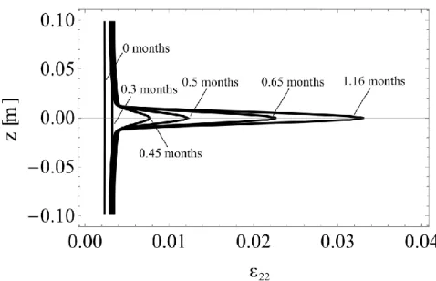
4.2 Compaction banding in oedometric compression
In the following we refer to the main results obtained by Stefanou and Sulem (2014) for oedometric compaction in a carbonate reservoir at 1.8 km depth because of CO2 injection.
The set of reactions that take place because of CO2 injection are summarized through the
stoichiometry of equation R3. In Table 2 we present some typical values for the chemo-mechanical parameters of a porous carbonate rock. At this depth, we assume that the water pressure is pf 18MPa and the total vertical stress is
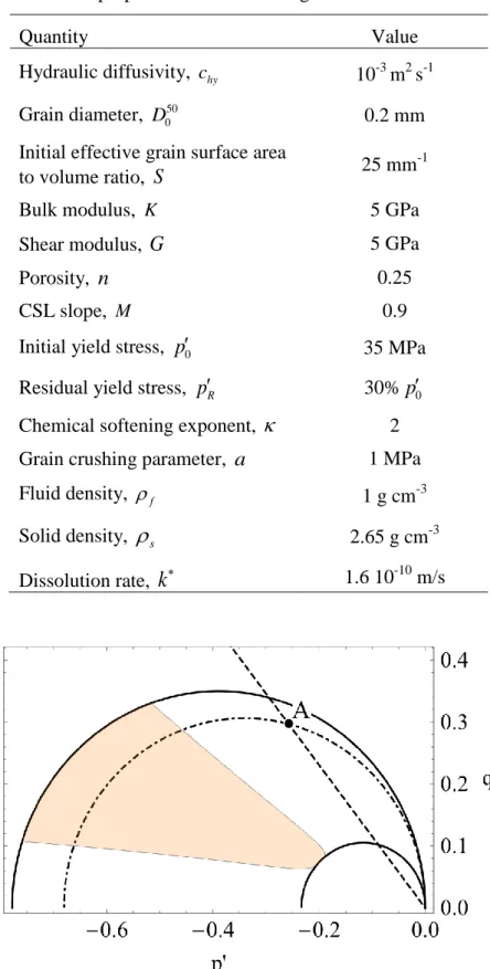
n 45MPa.Stefanou and Sulem (2014) have derived the instability conditions for which compaction bands formation is possible from a Linear Stability Analysis. The details of the analysis can be found in the aforementioned paper. In particular, there is a region in the qp plane where compaction band formation is possible. In other words homogeneous deformations are unstable and the system bifurcates to non-homogeneous solutions corresponding to compaction banding. Figure 12 shows the instability zone for the chemo-poro-mechanical parameters of the carbonate grainstone considered in this example.
Inside the instability region there exists a minimum critical wavelength above which perturbations are unstable (positive growth coefficient). This critical wavelength is related to the characteristic internal length, c, which was introduced in the previous paragraph. If
0
c then the system is unstable for any perturbation wave length. For more details on the
compaction band thickness and its relation to the reaction rate and the grain crushability we refer to Stefanou and Sulem (2014).
32
Table 2. Indicative material properties of a carbonate grainstone.
Quantity Value
Hydraulic diffusivity, chy 10-3 m2 s-1
Grain diameter, D050 0.2 mm
Initial effective grain surface area
to volume ratio, S 25 mm
-1
Bulk modulus, K 5 GPa
Shear modulus, G 5 GPa
Porosity, n 0.25
CSL slope, M 0.9
Initial yield stress, p0 35 MPa
Residual yield stress, pR 30%p0
Chemical softening exponent, 2
Grain crushing parameter, a 1 MPa
Fluid density, f 1 g cm-3
Solid density,
s 2.65 g cm-3Dissolution rate,
k
1.6 10-10 m/sFigure 12. Instability region (shaded) for compaction bands under oedometric conditions for a carbonate grainstone. The outer envelope (solid line ellipse) represents the initial strength of the material. The straight dashed line depicts the linear elastic oedometric path. Point A corresponds to the initial stress state at 1.8km depth. The inner ellipse (solid line) represents the residual strength of the grainstone after complete dissolution of the rock. The stresses are normalized by the applied vertical stress at 1.8 km depth, which is constant.
33
Initially we assume that the material is in a state of elastic deformation (Point A) under the applied total vertical stress of 45 MPa. At time t0, the injection of the CO2 solution starts.
It is assumed that the CO2 solution is continuously renewed in such a way that practically
open flow conditions hold (w t2
0
0). In field, CO2 injection open flow conditionswould correspond to a zone outside the gas plume, where the formation fluid is saturated with CO2, but is not in chemical equilibrium with the rock so that carbonate dissolution occurs
continuously (w2 w2eq). Rohmer and Seyedi (Rohmer & Seyedi, 2010) show that the dissolution front in a reservoir might extend few kilometers around the injection well after 10 years of continuous injection.
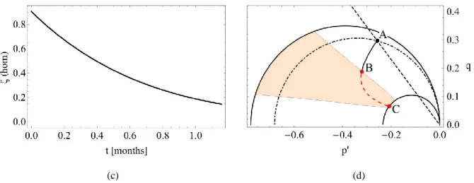
As a result of CO2 injection, the system is not in chemical equilibrium and dissolution occurs.
Consequently, the material is progressively degraded due to chemical softening and the chemical softening parameter decreases from its initial value
01. When
0.9 the material yields, plastic strains are accumulated and solid skeleton damage occurs (Eq.(31)). This phase of deformation under constant applied loading (i.e. the overburden) corresponds to the creep behavior that is observed due to CO2 injection (Le Guen et al., 2007; Liteanu &Spiers, 2009; Rutqvist, 2012).