HAL Id: hal-01230261
https://hal-iogs.archives-ouvertes.fr/hal-01230261
Submitted on 18 Nov 2015
HAL is a multi-disciplinary open access
archive for the deposit and dissemination of sci-entific research documents, whether they are pub-lished or not. The documents may come from teaching and research institutions in France or abroad, or from public or private research centers.
L’archive ouverte pluridisciplinaire HAL, est destinée au dépôt et à la diffusion de documents scientifiques de niveau recherche, publiés ou non, émanant des établissements d’enseignement et de recherche français ou étrangers, des laboratoires publics ou privés.
Generalized analytical model based on harmonic
coupling for hybrid plasmonic modes: Comparison with
numerical and experimental results
Mitradeep Sarkar, Jean-François Bryche, Julien Moreau, Mondher Besbes,
Gregory Barbillon, Bernard Bartenlian, Michael Canva
To cite this version:
Mitradeep Sarkar, Jean-François Bryche, Julien Moreau, Mondher Besbes, Gregory Barbillon, et al.. Generalized analytical model based on harmonic coupling for hybrid plasmonic modes: Comparison with numerical and experimental results. Optics Express, Optical Society of America - OSA Publish-ing, 2015, 23 (21), pp.27376. �10.1364/OE.23.027376�. �hal-01230261�
Generalized analytical model to describe plasmonic modes
resulting from the harmonic coupling of localized plasmons
to propagating plasmons
Mitradeep Sarkar1, Jean-François Bryche1,2, Julien Moreau1, Mondher Besbes1, Grégory Barbillon2, Bernard
Bartenlian2, Michael Canva1*
1 Laboratoire Charles Fabry (LCF),Institut d’Optique Graduate School , Université Paris Sud , CNRS, Campus Paris Saclay, 2 avenue Augustin Fresnel, 91127 Palaiseau, France
2 Institut d'Électronique Fondamentale (IEF), Université Paris Sud , CNRS, Bâtiment 220, 2 Rue André Ampère, 91405 Orsay, France *[email protected]
Abstract: Metal nanoparticle arrays have proved useful for different applications due to their
ability to enhance electromagnetic fields within a few tens of nanometers. This field enhancement results from the excitation of various plasmonic modes at certain resonance frequencies. In this article, we have studied an array of metallic nanocylinders placed on a thin metallic film. A simple analytical model is proposed to explain the existence of the different types of modes that can be excited in such a structure. Owing to the cylinder array, the structure can support localized surface plasmon (LSP) modes. The LSP mode couples to the propagating surface plasmon (PSP) mode of the thin film to give rise to the hybrid lattice plasmon (HLP) mode and anti-crossing phenomenon. Due to the periodicity of the array, the Bragg modes (BM) are also excited in the structure. We have calculated analytically the resonance frequencies of the BM, LSP and the corresponding HLP, and have verified the calculations by rigorous numerical methods. Experimental results obtained in the Kretschmann configuration also validate the proposed analytical model. The dependency of the resonance frequencies of these modes on the structural parameters such as cylinder diameter, height and the periodicity of the array is shown. Such a detailed study can offer insights on the physical phenomenon that governs the excitation of various plasmonic modes in the system. It is also useful to optimize the structure as per required for the different applications, where such types of structures are used.
©2014 Optical Society of America
OCIS codes: (000.0000) General; (000.2700) General science.
References and links
1. W. L. Barnes, A. Dereux, and T. W. Ebbesen, "Surface plasmon subwavelength optics," Nature 424, 824-830 (2003).
2. J. Nelayah, M. Kociak, O. Stephan, F. J. G. de Abajo, M. Tence, L. Henrard, D. Taverna, I. Pastoriza-Santos, L. M. Liz-Marzan, and C. Colliex, "Mapping surface plasmons on a single metallic nanoparticle," Nat Phys 3, 348-353 (2007).
3. T. Springer, M. L. Ermini, B. Spackova, J. Jablonku, and J. Homola, "Enhancing Sensitivity of Surface Plasmon Resonance Biosensors by Functionalized Gold Nanoparticles: Size Matters," Anal Chem 86, 10350-10356 (2014).
4. P. G. Etchegoin and E. C. Le Ru, "A perspective on single molecule SERS: current status and future challenges," Phys Chem Chem Phys 10, 6079-6089 (2008).
5. G. C. Schatz, M. A. Young, and R. P. Van Duyne, "Electromagnetic mechanism of SERS," Top Appl Phys 103, 19-45 (2006). 6. H. A. Atwater and A. Polman, "Plasmonics for improved photovoltaic devices," Nat Mater 9, 205-213 (2010).
7. S. Chen, L. Y. Meng, J. W. Hu, and Z. L. Yang, "Fano Interference Between Higher Localized and Propagating Surface Plasmon Modes in Nanovoid Arrays," Plasmonics 10, 71-76 (2015).
8. A. Lovera, B. Gallinet, P. Nordlander, and O. J. F. Martin, "Mechanisms of Fano Resonances in Coupled Plasmonic Systems," Acs Nano 7, 4527-4536 (2013).
9. B. Luk'yanchuk, N. I. Zheludev, S. A. Maier, N. J. Halas, P. Nordlander, H. Giessen, and C. T. Chong, "The Fano resonance in plasmonic nanostructures and metamaterials," Nat Mater 9, 707-715 (2010).
10. N. Papanikolaou, "Optical properties of metallic nanoparticle arrays on a thin metallic film," Physical Review B 75(2007).
11. Y. Z. Chu and K. B. Crozier, "Experimental study of the interaction between localized and propagating surface plasmons," Opt Lett
34, 244-246 (2009).
12. C. Forestiere, L. Dal Negro, and G. Miano, "Theory of coupled plasmon modes and Fano-like resonances in subwavelength metal structures," Physical Review B 88(2013).
13. T. J. Davis, D. E. Gomez, and K. C. Vernon, "Simple Model for the Hybridization of Surface Plasmon Resonances in Metallic Nanoparticles," Nano Lett 10, 2618-2625 (2010).
14. J. B. Lassiter, F. McGuire, J. J. Mock, C. Ciraci, R. T. Hill, B. J. Wiley, A. Chilkoti, and D. R. Smith, "Plasmonic Waveguide Modes of Film-Coupled Metallic Nanocubes," Nano Lett 13, 5866-5872 (2013).
15. Y. Francescato, V. Giannini, and S. A. Maier, "Plasmonic Systems Unveiled by Fano Resonances," Acs Nano 6, 1830-1838 (2012). 16. F. Zhou, Y. Liu, and W. P. Cai, "Huge local electric field enhancement in hybrid plasmonic arrays," Opt Lett 39, 1302-1305 (2014).
17. K. Lodewijks, J. Ryken, W. Van Roy, G. Borghs, L. Lagae, and P. Van Dorpe, "Tuning the Fano Resonance Between Localized and Propagating Surface Plasmon Resonances for Refractive Index Sensing Applications," Plasmonics 8, 1379-1385 (2013).
18. D. Y. Lei, A. I. Fernandez-Dominguez, Y. Sonnefraud, K. Appavoo, R. F. Haglund, J. B. Pendry, and S. A. Maier, "Revealing Plasmonic Gap Modes in Particle-on-Film Systems Using Dark-Field Spectroscopy," Acs Nano 6, 1380-1386 (2012).
19. M. Sarkar, M. Besbes, J. Moreau, J.-F. Bryche, A. Olivéro, G. Barbillon, A.-L. Coutrot, B. Bartenlian, and M. Canva, "Hybrid Plasmonic Mode by Resonant Coupling of Localized Plasmons to Propagating Plasmons in a Kretschmann Configuration," Acs Photonics 2, 237-245 (2015).
20. Y. Chang and Y. Jiang, "Multiple surface plasmon polaritons modes on thin silver film controlled by a two-dimensional lattice of silver nanodimers," J Nanopart Res 17, 1-8 (2015).
21. V. Yannopapas, "Periodic Arrays of Film-Coupled Cubic Nanoantennas as Tunable Plasmonic Metasurfaces," Photonics 2, 270-278 (2015).
22. A. Hohenau and J. R. Krenn, "Plasmonic modes of gold nano-particle arrays on thin gold films," Phys Status Solidi-R 4, 256-258 (2010).
23. S. H. Shams Mousavi, A. A. Eftekhar, A. H. Atabaki, and A. Adibi, "Band-edge Bilayer Plasmonic Nanostructure for Surface Enhanced Raman Spectroscopy," Acs Photonics (2015).
24. P. B. Johnson and R. W. Christy, "Optical Constants of the Noble Metals," Physical Review B 6, 4370-4379 (1972).
25. J. P. Hugonin, M. Besbes, and P. Lalanne, "Hybridization of electromagnetic numerical methods through the G-matrix algorithm," Opt Lett 33, 1590-1592 (2008).
26. M. Sarkar, M. Chamtouri, J. Moreau, M. Besbes, and M. Canva, "Introducing 2D confined propagating plasmons for surface plasmon resonance sensing using arrays of metallic ribbons," Sensor Actuat B-Chem 191, 115-121 (2014).
27. D. M. Solis, J. M. Taboada, F. Obelleiro, L. M. Liz-Marzan, and F. J. G. de Abajo, "Toward Ultimate Nanoplasmonics Modeling," Acs Nano 8, 7559-7570 (2014).
28. C. Noguez, "Surface Plasmons on Metal Nanoparticles: The Influence of Shape and Physical Environment," J Phys Chem C 111, 3806-3819 (2007).
29. R. Giannini, C. V. Hafner, and J. F. Löffler, "Scaling Behavior of Individual Nanoparticle Plasmon Resonances," The Journal of Physical Chemistry C 119, 6138-6147 (2015).
30. A. Zehe and A. Ramirez, "The depolarization field in polarizable objects of general shape," Rev Mex Fis 48, 427-431 (2002). 31. A. Mejdoubi and C. Brosseau, "Finite-element simulation of the depolarization factor of arbitrarily shaped inclusions," Phys Rev E
74(2006).
32. K. C. Vernon, A. M. Funston, C. Novo, D. E. Gomez, P. Mulvaney, and T. J. Davis, "Influence of Particle-Substrate Interaction on Localized Plasmon Resonances," Nano Lett 10, 2080-2086 (2010).
33. T. J. Davis, K. C. Vernon, and D. E. Gomez, "Designing plasmonic systems using optical coupling between nanoparticles," Physical Review B 79(2009).
34. V. Myroshnychenko, J. Rodriguez-Fernandez, I. Pastoriza-Santos, A. M. Funston, C. Novo, P. Mulvaney, L. M. Liz-Marzan, and F. J. G. de Abajo, "Modelling the optical response of gold nanoparticles," Chem Soc Rev 37, 1792-1805 (2008).
35. H. Raether, "Surface-Plasmons on Smooth and Rough Surfaces and on Gratings," Springer Tr Mod Phys 111, 1-133 (1988).
36. M. Piliarik and J. Homola, "Surface plasmon resonance (SPR) sensors: approaching their limits?," Opt Express 17, 16505-16517 (2009).
37. L. Novotny, "Strong coupling, energy splitting, and level crossings: A classical perspective," Am J Phys 78, 1199-1202 (2010). 38. W. L. Barnes, T. W. Preist, S. C. Kitson, and J. R. Sambles, "Physical origin of photonic energy gaps in the propagation of surface plasmons on gratings," Physical Review B 54, 6227-6244 (1996).
39. M. Chamtouri, A. Dhawan, M. Besbes, J. Moreau, H. Ghalila, T. Vo-Dinh, and M. Canva, "Enhanced SPR Sensitivity with Nano-Micro-Ribbon Grating-an Exhaustive Simulation Mapping," Plasmonics 9, 79-92 (2014).
40. M. Chamtouri, M. Sarkar, J. Moreau, M. Besbes, H. Ghalila, and M. Canva, "Field enhancement and target localization impact on the biosensitivity of nanostructured plasmonic sensors," J. Opt. Soc. Am. B 31, 1223-1231 (2014).
41. H. Gao, J. M. McMahon, M. H. Lee, J. Henzie, S. K. Gray, G. C. Schatz, and T. W. Odom, "Rayleigh anomaly-surface plasmon polariton resonances in palladium and gold subwavelength hole arrays," Opt Express 17, 2334-2340 (2009).
42. D. Barchiesi, S. Kessentini, N. Guillot, M. L. de la Chapelle, and T. Grosges, "Localized surface plasmon resonance in arrays of nano-gold cylinders: inverse problem and propagation of uncertainties," Opt Express 21, 2245-2262 (2013).
43. J. Grand, M. L. de la Chapelle, J. L. Bijeon, P. M. Adam, A. Vial, and P. Royer, "Role of localized surface plasmons in surface-enhanced Raman scattering of shape-controlled metallic particles in regular arrays," Physical Review B 72(2005).
44. X. L. Wang, P. Gogol, E. Cambril, and B. Palpant, "Near- and Far-Field Effects on the Plasmon Coupling in Gold Nanoparticle Arrays," J Phys Chem C 116, 24741-24747 (2012).
45. F. Marquier, J. J. Greffet, S. Collin, F. Pardo, and J. L. Pelouard, "Resonant transmission through a metallic film due to coupled modes," Opt Express 13, 70-76 (2005).
46. A. T. M. A. Rahman, P. Majewski, and K. Vasilev, "Extraordinary optical transmission: coupling of the Wood-Rayleigh anomaly and the Fabry-Perot resonance," Opt Lett 37, 1742-1744 (2012).
47. T. W. Ebbesen, H. J. Lezec, H. F. Ghaemi, T. Thio, and P. A. Wolff, "Extraordinary optical transmission through sub-wavelength hole arrays," Nature 391, 667-669 (1998).
48. M. G. Moharam, E. B. Grann, D. A. Pommet, and T. K. Gaylord, "Formulation for Stable and Efficient Implementation of the Rigorous Coupled-Wave Analysis of Binary Gratings," J Opt Soc Am A 12, 1068-1076 (1995).
49. M. Nakkach, A. Duval, B. Ea-Kim, J. Moreau, and M. Canva, "Angulo-spectral surface plasmon resonance imaging of nanofabricated grating surfaces," Opt Lett 35, 2209-2211 (2010).
50. A. Sereda, J. Moreau, M. Canva, and E. Maillart, "High performance multi-spectral interrogation for surface plasmon resonance imaging sensors," Biosensors and Bioelectronics 54, 175-180 (2014).
1. Introduction
Metallic structures at nanometric scale, smaller than the wavelength of light, have been studied in plasmonics for some time now due to their ability to enhance local electromagnetic field in their vicinity.[1] [2] Such enhancement of the local field has been attributed to the plasmon polaritons excited in such structures. In isolated metallic nanoparticles, the incident light can interact with the surface electrons of the conduction band of the metal, and the collective oscillations of these electrons can give rise to intense local electromagnetic fields at the metal-dielectric interface. This resulting localized surface plasmon (LSP) has been effectively used for numerous applications such as surface-enhanced Raman scattering (SERS), drug delivery, chemical sensing, cancer therapy, and new photonic devices.[3] [4] [5] [6] The typical penetration depths of the confined field close to the metallic surface are of the order of a few tens of nanometers, and thus these nanoparticles can work as excellent transducers of local refractive index changes, which can be used for various applications of biomolecular detection. One such technique is the surface plasmon resonance (SPR) detection. However, unique nanoparticles have proved to be less efficient than thin films for this application due to their low spectral dispersion and weak scattering cross-sections.
Uniform metal-dielectric interfaces can sustain propagating surface plasmon polaritons (PSP), which have large spectral dispersion and are more conventionally used for SPR detections. Recent work has been aimed at coupling the excitation of these two plasmon polaritons by nanostructuration of the metal-dielectric interface.[7] [8] [9] Nanostructuration can induce coupling between various plasmonic modes excited in the structures.[10] [11] [12] Such couplings have been extensively studied, and various models have been developed to explain the existence of different modes in structures.[13] [14] [15] In most of the above cited articles, such coupling has been described as Fano-like resonances. However we will show in our work that the coupling between two plasmonic modes can be described by a harmonic oscillator model and not by Fano-resonances. The plasmonic modes which participate in the coupling are rather both “broad states” and Fano resonance occurs only for coupling of “broad” and “discrete” states.
In this article, we study an array of metallic nanoparticles placed on a thin metallic film. Such a structure is promising for sensor applications due to its ability to harmonically couple the LSP and PSP modes. Similar structures have been studied recently but with a sandwiched spacer layer between the nanostructures and the uniform film.[16] [17] [18] However, such a sandwiched dielectric layer, because it tends to concentrate the electromagnetic field into it severely limits the application of such structures for biodetection. In a recent publication,[19] we have demonstrated that such all-metallic structure can give rise to the hybrid lattice plasmon (HLP) mode, which has a high field confinement characteristic of the LSP, but at the same time a high dispersion similar to the PSP. In order to optimize a structure for different applications, it is important to understand the basic mechanism behind the excitation of each plasmonic mode present in the structure. Modes similar to the ones presented here have been found in nanoparticle arrays on metallic thin film.[20] [21] [22] [23] However, the complete mechanism of the mode excitation in the structure with analytical formulations, and its dependence on structural parameters was not discussed in the above-mentioned publications.
In this article, we put forward a simple analytical model to predict the existence of different plasmonic modes and their excitation. In this model, we study the dependence of the structural parameters namely the periodicity, and the diameter of the cylinders on the coupling between the LSP and the PSP modes. These numerical calculations are furthermore validated by both rigorous numerical methods and experimental results obtained with a SPR imaging setup working in the Kretschmann configuration.
2. Numerical methods for rigorous calculations
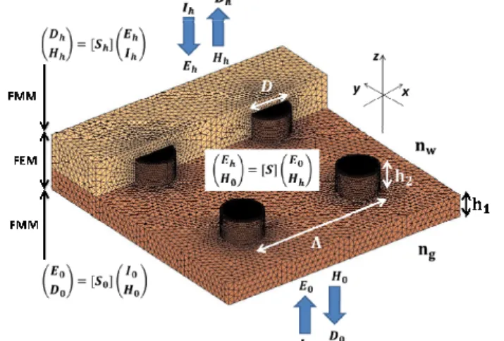
The structure studied for this work consists of a gold nanocylinder array with a diameter D, a height h2, and a
period Λ. The array is placed on a gold film of height (h1) of 30 nm. The refractive index of gold used for
calculations are the values of Johnson and Christy.[24] The medium surrounding the cylinders is water (refractive index nw), keeping in mind the applications of these structures to biomolecular detection. The medium below the gold film is considered to be semi-infinite with the refractive index of BK7 glass (ng).
The numerical model used is a combination of two well-known methods namely the Fourier modal method (FMM) and the finite element methods (FEM).[19] [25] [26] However, such rigorous numerical methods are time consuming (around a few hundreds of seconds to calculate the electromagnetic field at a given wavelength and incident angle), and have high memory requirements. The time and memory requirements of such methods often become unreasonable even with the availability of commercial software and powerful computers.[27] Thus, we propose a simple analytical model, which can be used furthermore to better understand the physical excitation of the various modes, and calculate their resonance frequency dispersions with negligible requirements in terms of
calculation time and memory. The analytical model was validated by rigorous numerical simulations and also by experimental results.
The structure geometry and a brief scheme of the rigorous calculation used are shown in Figure 1. For the calculation, the light was considered to be TM polarized (electric field along x and z and magnetic field along y as per the coordinates in Figure 1), because a component perpendicular to the metal-dielectric interface (z) is required to excite the PSP. For TE polarized light only the LSP can be excited, and thus all the other plasmonic modes based on the PSP, studied in this article were verified to be non-existent in the calculations and experiments.
Fig 1. The studied structure geometry consists of an array of metallic cylinders of diameter D and height h2 placed on a thin metallic film of
height h1. The refractive index on the side of the array was taken as nw while that on the other side was ng. A sketch of the numerical method is
also shown, which uses a mesh around the nanostructured region to calculate the S matrix by FEM, and then uses FMM to calculate the far-field response of the system.
3. Analytical model for the plasmonic modes in the structure
3.1 The localized surface plasmon mode.
The presence of the nanocylinders gives rise to a localized surface plasmon (LSP) mode. The resonance
frequencies (ω = k0c where k0 is the free space wave-vector) for the LSP modes in the case of isolated nanoparticles
can be found from the equation of the polarizability given by
1
where nm and nd are the refractive indices of metal and dielectric surrounding the cylinders, respectively.
We must mention here that the pole of the polarizability function is sufficient to calculate the resonance frequencies only for isolated nanoparticles, without any coupling of the LSP modes with other modes. In this article, we will use equation 1 to calculate the resonance frequencies, and then demonstrate that this value can be used as a starting point to calculate the resonance frequencies of the other plasmonic modes that result from the coupling of LSP with the PSP. The parameter χ is called the depolarization factor, and depends on the shape and size of the
particles.[28] [29] χ for cylinders can be written as 1 , where h2 is the height of the cylinder and D its
diameter. This relation was derived from reports based on dielectric structures [30] [31] however they also apply for metal cylinders presented in this work. It should be noted here that the depolarization factor used here, depends largely on the cylinder height, and thus the LSP mode that is excited, is oriented along the axis of the cylinder. To excite this mode, we need an electric field component along the cylinder axis (z-axis), and thus, this mode can be excited only for TM configuration. For TE configuration, only the LSP mode perpendicular to the cylinder axis can be excited and the relation for χ will be different. However, we will not consider this mode in this article.
The LSP depends largely on the surrounding medium and the resonance frequencies shift, when the particles are supported by a substrate. It has been shown elsewhere that the effect of the substrate can be analytically calculated using the pseudo-particle concept[32] [33], and the method of images.[34] In such a model, the refractive index of
1 1
1 1 2
where γ = 1/(1-2χ) and η = (nd2-nm2)/(nd2+nm2) considering the substrate as the metallic film. The factor T depends
on the shape, and the aspect ratio of the particles. For the cylinders, it can be evaluated to be T = -3ndχ/(π(1-2χ)).
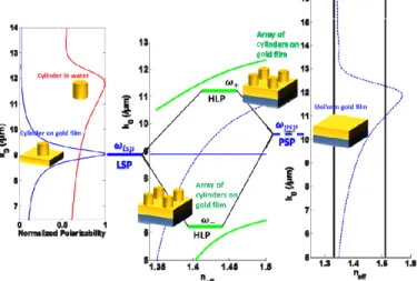
The analytical calculation of α(k0) is shown in Figure 2 (left) for a cylinder of height 30 nm, and diameter 50 nm as
a function of k0. The medium surrounding the cylinder was taken to be water with a refractive index of nd = nw.
When the cylinder is supported by a metallic film, the resonance frequencies shift to lower energies and there is also a narrowing of the resonance linewidth.
This calculation is, however, valid only for single nanoparticles. We will demonstrate in this article that a simple analytical model based on the coupling between the PSP and the LSP, can be found in the case of an array of nanoparticles on a thin metallic film.
Fig. 2. At left, the analytically calculated polarizability α(k0) for a nanocylinder of 30 nm height and 50 nm diameter in a homogenous medium nw
(in red). The same for the cylinder placed on a semi-infinite gold medium (in blue). The calculated LSP frequency for the later configuration is k0
= 8.87 µm-1. At center, the HLP mode (green) dispersion, which results from the harmonic coupling of the LSP and PSP. At right, the calculated
dispersion (k0-neff) for the PSP in a gold film with plasmons propagating in the medium nw. The resonance frequencies of the LSP (blue solid) and
the PSP (blue dotted) are also shown. For this scheme, the period of the array was taken as 180 nm. 3.2 Harmonic coupling for the LSP and the PSP.
The uniform gold layer can support the propagating surface plasmon (PSP) mode in the structure, the dispersion relation of which is given by the well-known equation
: 3
The PSP mode propagates along the metal-dielectric interface, and has a propagation length of the order of few µm and penetration depths of around 150 nm. In Figure 2 (right), the dispersion of the PSP is shown as a function of
k0 and neff = kx/k0, where kx is the in plane wave-vector in the direction of the propagation of the PSP. We choose to
use the notation neff inspired from its use in guided optics, mentioned in some plasmonic literature [35] [36], and as
used in our recent publication.[19] In respect to plasmonic modes, kx serves as a direct representation of the
dispersion. However, in terms of experimental configuration using neff directly shows the range of values that can be accessed, from 0 to that which corresponds to the refractive index of the incident medium. Also, for a dispersion
map with respect to kx-k0 as it conventionally used, the PSP lies within a sharp cone between the light-line of the
two dielectric media surrounding the metal film. In a representation neff-k0 this zone is broadened and thus easier to
visualize.
We will now suppose that the modes in the complete structure can be explained by the combination of two
resonant plasmonic modes namely the LSP and the PSP. For the range of values of neff, where both the modes can be
excited, we will consider a harmonic coupling between them. Such harmonic coupling can be treated classically as
shown by Novotny et al.[37] For two oscillators with resonance frequencies of ω1 = k1c and ω2 = k2c, the
1
2 4 4
where κ is a coupling parameter, and the only free parameter used in this model. The scheme of the coupling is
displayed in Figure 2. The coupling parameter κ has a dimension of 1/τ2 where τ has a unit of time (s). We have
found that this value of τ does not depend on the periodicity of the structure, and depends weakly on the aspect ratio
of the nanocylinders. The coupling parameter can be written as κ = (1/τ2)×(h
2+D)/Λ. This dependency, inversely
proportional to period Λ, and directly proportional to h2+D, will be justified from the results presented in subsequent
sections of this article. Thus, the only parameter needed to fit for our results will be τ, and its value was found to be 0.37 ± 0.03 fs by fitting the rigorous numerical calculations with equation 4. We have used this same unique value for all the calculations.
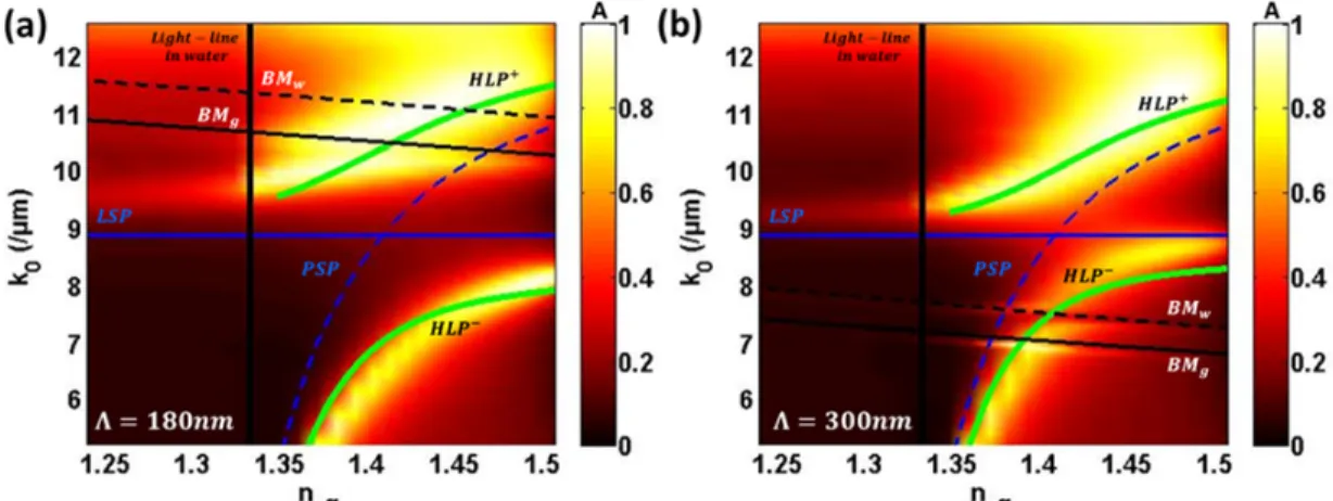
Figure 3 shows the absorption map obtained by numerical calculations as a function of k0 and neff for Λ = 180 nm,
and Λ = 300 nm for cylinder height of h2 = 30 nm, and D = 50 nm. The uniform gold film width (h1) was taken to be
30 nm. The resonance frequencies of the LSP and PSP are displayed (blue solid and blue dashed, respectively). The PSP splits around the LSP giving two branches of the coupled mode which we call the Hybrid Lattice Plasmon
(HLP), the HLP+ with higher frequencies and the HLP- with lower frequencies. This phenomenon of anti-crossing
and the existence of a bandgap are fundamental in cases of harmonic coupling between two oscillators, and the width of the bandgap is proportional to the coupling parameter κ.[37] [38] The analytical calculation of the resonance frequencies of the HLP given by equation 4, is also plotted for comparison. We observe that the dispersion of the HLP mode as calculated by equation 4 fits remarkable well to the numerically calculated absorption maxima of the structure.
We must mention here that to excite the plasmonic modes, we must match the k0 and neff of the incident light to
that of the modes. For neff < nw, the incident light can be coupled directly to the modes of the structure by
illuminating it with a plane-wave from water at an incident angle θ, and the corresponding neff = nwsin(θ). To access the values of neff > nw, we need to use the Kretschmann configuration (with refractive index of the incident medium >
nw) to excite the modes beyond the light-line in water.
Fig. 3. . (a) The normalized absorption (A) dispersion map as a function of k0 and neff for h2 = 30 nm, D = 50 nm, and period Λ = 180 nm with the
medium around the nanocylinders of refractive index nw. The lightline in the medium is defined as neff = nw. The proposed analytical calculation of
the dispersion of different modes of the system are also shown: LSP (blue solid), PSP (blue dashed), HLP (green), and BMs (black solid and dashed). (b) Same as (a) for period Λ = 300 nm.
3.3 The Bragg modes in a periodic structure.
In Figure 3, we also observe the existence of other bandgaps that can be attributed to the coupling of the HLP (and in turn the PSP) with the Bragg Modes (BM) of the structure. Such modes were reported in our earlier publication for a binary metallic grating, which shows that the existence of the BM is independent of the structure shape.[39] [40] In short, the presence of the array of nanocylinders affects the PSP, which is reflected, leading to an interference of the contra-propagating plasmons. Such interferences give rise to the Bragg-modes (BM), which results in a confinement of the electromagnetic fields around the nanostructures. The dispersion of these modes as shown elsewhere can be written as[41]
where kB = 2π/Λ is the Bragg wave-vector, Λ is the periodicity of the structure and m is the order of the mode. For this type of structure, we can have two BMs resulting from the interference of the PSP propagating in the two
different dielectric media on two sides of the metal film. The BM at higher frequencies (higher k0) results from the
interference of the PSP propagating in the medium surrounding the cylinders (water, BMw, calculated using nd = nw
in Equation 3 and 5) while that at lower k0 results from the PSP in the substrate (glass, BMg, calculated using nd = ng
in Equation 3 and 5). They are shown in Figure 3. Below the critical angle (neff < nw), only the BM can be excited, and the absorption of these modes is very weak as compared to the HLP mode. For values of neff, where the PSP and in turn the HLP are excited, we have a harmonic coupling between them, and the BM to form a bandgap. From
Figure 3(b), the absorption maxima are slightly shifted from the analytically calculated HLP- for values of k
0 larger than the BM frequencies. This is due to splitting of the HLP by its coupling to the BM. A relation similar to equation 4 can be written to describe this coupling between the HLP and BM. We will not consider this for simplicity.
4. Dependence of the structural parameters on the coupling
4.1 Dependence of periodicity of the structure.
The periodicity of the structure was varied within the range of 100 nm to 550 nm. In this range, the resonance frequencies of the LSP do not depend on the periodicity as the mode is strongly confined close to the cylinders with a penetration depth of a few tens of nanometers. Interaction between adjacent cylinders is negligible. The complete
absorption maps as a function of k0 and neff for different periods of the structure were calculated (see Appendix,
Figure A1).
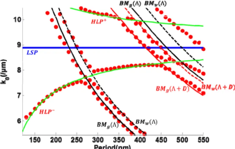
Figure 4 summarizes the resonance frequencies of all the different modes (absorption maxima calculated by
rigorous numerical methods) as a function of the structure period within the range of k0 = 5.2 µm-1 to 10.5 µm-1 for
neff = 1.42. We can observe that the resonance frequencies of HLP+ and HLP- approach the frequency of the LSP for
increasing period. We see in equation 4 that as the coupling parameter decrease, the frequencies of HLP ( )
approach the frequencies ω1 and ω2 which are of the PSP and the LSP respectively. Using κ = (1/τ2)×(h2+D)/Λ, the
calculated resonance frequencies of the HLP mode fits perfectly with absorption maxima of the structures obtained numerically and thus justifies that κ ∝ 1/Λ. The large dispersion of the HLP mode, similar in that respect to a classical propagating plasmon and the fact that the resonance frequency of the HLP can be tuned by changing the periodicity of the structure, can prove useful for various surface plasmon based applications.
Figure 4 also shows the numerical and analytical resonance frequencies of the different BM, with orders m in equation 5, which can be generated in these structures. For higher periods, the BM resulting from the periodicity of
Λ+D can also be excited, satisfying equation 5 with kB = 2π/(Λ+D) and m = 2.
Fig. 4. The resonance frequencies (k0) of all the modes in the structure (D = 50 nm, h2 = 30 nm) manifest as absorption maxima in the dispersion
map calculated by rigorous numerical method (red dots) as a function of array period for neff = 1.42. We have superposed the analytically
calculated frequencies of the modes as a function of period: LSP (blue), HLP (green), BMs calculated for kB = 2π/(Λ) (black solid and dashed)
and BMs for kB = 2π/(Λ+D) (red dashed and solid). (please distinguish in figure first and second order BM)
At the frequencies where the BM is excited, we have the appearance of bandgaps and absorption maxima around those bandgaps. The excellent agreement between the analytical model and the rigorous numerical calculations, over
a wide range of periods, further validates the proposed analytical model which can be effectively used to calculate the resonance frequencies of the plasmonic modes present in the structure.
4.2 Effect of height and diameter of the cylinders
There is no effect of the gold film height (h1) on the resonance frequencies of the modes, and this was shown in
our recent publication[19], and also by Chang et al[20] in a similar structure. Indeed, h1 affects only the PSP, and
thus it can affect the contrast of absorption but not the resonance frequencies. For the cylinders, the height (h2) and
diameter (D) were varied within the range of 30 nm to 90 nm for Λ = 350 nm (see Appendix, Figure A2). As can be seen from equation 1, the LSP resonance frequencies decrease (resonance wavelengths increase) with increasing height, and increase slightly with increasing diameter. It is interesting to note that this trend is opposite to what has been reported for arrays of cylinders on a glass substrate.[42] [43] [44] Indeed, in this configuration, the electric field along z-axis plays a major role in the excitation of the LSP, and thus the LSP is oriented along the cylinder axis. In the above cited works, the LSP mode perpendicular to the cylinder axis (x-y plane) was studied, and thus
their dependences on D and h2 are opposite compared to that we report here.
Fig. 5(a) The resonance frequencies (k0) of HLP modes in the structure (Λ = 350 nm, D = 50 nm) manifest as absorption maxima in the
dispersion map calculated by rigorous numerical method (red dots) as a function of cylinder height (h2) for neff = 1.45. We have superposed the
analytically calculated frequencies of the modes as a function of h2: LSP (blue), HLP (green). (b) For D = 90 nm with the same period as
previously.
The resonance frequencies of the LSP as calculated by the analytical model, are shown in Figure 5 (blue line) for
different h2 and D for neff = 1.45. The resonance frequencies of HLP+ and HLP- (absorption maxima) calculated by
the rigorous numerical method are also displayed in Figure 5 (red dots) along with the analytically calculated HLP dispersion (green line). The HLP modes are pushed further away from the LSP for larger heights of the cylinder. This trend is opposite to what we have for increasing periods. This result indicates that the coupling parameter (κ) is
proportional to h2. Now comparing figure 5(a) with figure 5(b) we see that the resonance frequencies of the HLP
modes also pushed away from that of the LSP for larger diameters and thus κ is also proportional to D. Using κ = (1/τ2)×(h
2+D)/Λ we have an excellent fit with the absorption minima calculated numerically and the analytical
model.
Like the period, the height of the nanocylinders also has a major effect on the resonance frequencies of the HLP which can be tuned over a range of k0 = 6 µm-1 - 9 µm-1.
4.3 Reflection and transmission characteristics of the modes.
The far field reflection and transmission properties of the structure, as a function of the incident wavelength and angle, needs to be studied as it corresponds to what is generally measured experimentally in an SPR setup. This is the subject of this section.
The reflection and transmission maps of the structure with period of 340 nm, h2 = 30 nm and D = 50 nm are
displayed in Figure 6. For this calculation, the Kretschmann configuration was considered to have access to all the values of neff from 0 to the light-line in glass (ng). Below the light-line in water neff = nw only the BM can be excited.
from the drastic drop in reflection. However, an interesting feature of the HLP is that it can also radiate up to 25% of
the energy into transmission. This transmission was found strictly for HLP- and for the resonance frequencies greater
than the resonance frequencies of the BMw. Such transmission was reported numerous times for various structured
arrays of nanoholes.[45] [46] [47] We observe this transmission only for the HLP- mode and for frequencies above
the frequencies of BMw. Though no clear explanation for this phenomenon was found we believe that the
transmission may be a result of the coupling of the HLP with the BMw, which itself is caused by the PSP
propagating on the side of the cylinders.
Fig 6. The normalized reflectivity (R) dispersion map as a function of k0 and neff for h2 = 30 nm, D = 50 nm and period Λ = 340 nm with the
medium around the nanocylinders of refractive index nw in the Kretschmann configuration. The lightline in the medium is defined as neff = nw. The
analytical calculation of the dispersion of different modes of the system are also shown: LSP (blue solid), PSP (blue dashed), HLP (green) and BMs (black and red solid and dashed same as figure 4). (b) The transmission (T) for the same parameters.
5. Experimental results
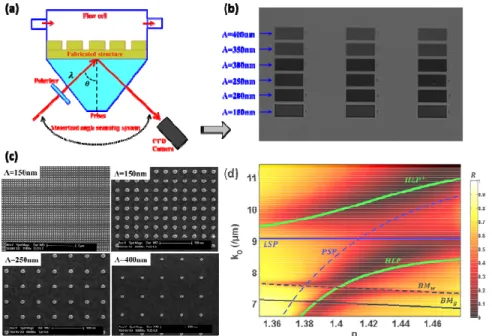
Fig 7. (a) Scheme of the SPR imaging system used to characterize the fabricated nanostructure in the Kretschmann configuration. (b) An image of the structured chip with 3×6 zones as obtained by the SPR imaging system. Each zone has a size of 500 × 500 µm2 and has the same structural
parameters (diameter and periodicity of cylinders) along the rows. The period is changed from 150 nm to 400 nm along the columns as shown in the figure. (c) SEM images of cylinder with a diameter of 50 nm and periods of 150 nm, 250 nm and 400 nm. (d) The experimental reflectivity
(R) dispersion map as a function of k0 and neff for h2 = 30 nm, D = 50 nm and period Λ = 300 nm. The experimental reflectivity map should be
compared to the numerical absorption map of figure 3(b), which has the same structural dimensions. The analytical calculation of the dispersion of different modes of the system is also shown.
The nanostructure studied was fabricated using e-beam lithography on a BK7 glass substrate and characterized with SEM measurements. On the same chip, we were able to obtain different gold nano cylinders arrays with a diameter of 50 nm and different periods ranging from 150 nm to 400 nm. This allows us to simultaneously observe all nanostructurated areas using an SPRI setup working in Kretschmann configuration. In this configuration, we
have access to the values of neff beyond the critical angle of glass-water interface (neff > nw), and thus excite the PSP and all the other modes presented in this article.
The complete dispersion maps as a function of wavelength (λ) and incident angle (θ), were extracted for each zone with different periods of structures (see Appendix, Figure A3). As an example, the complete reflectivity
dispersion map as a function of k0 = 2π/λ and neff = ngsinθ (the refractive index of BK7 glass taken as ng = 1.513) for
Λ = 300 nm is shown in Figure 7(d). The experimental results are very close to the dispersion maps calculated numerically in Figure 3(b) for the same structural dimensions. The contrast of the experimental reflectivity is a bit lower (ratio of maximum to minimum of R and the maximum R is little less than 1 in experiment) than that shown in Figure 6(a) or that of the absorption map of Figure 3(b), and this is mainly a result of absorption of the adhesion layer (2 nm of titanium).
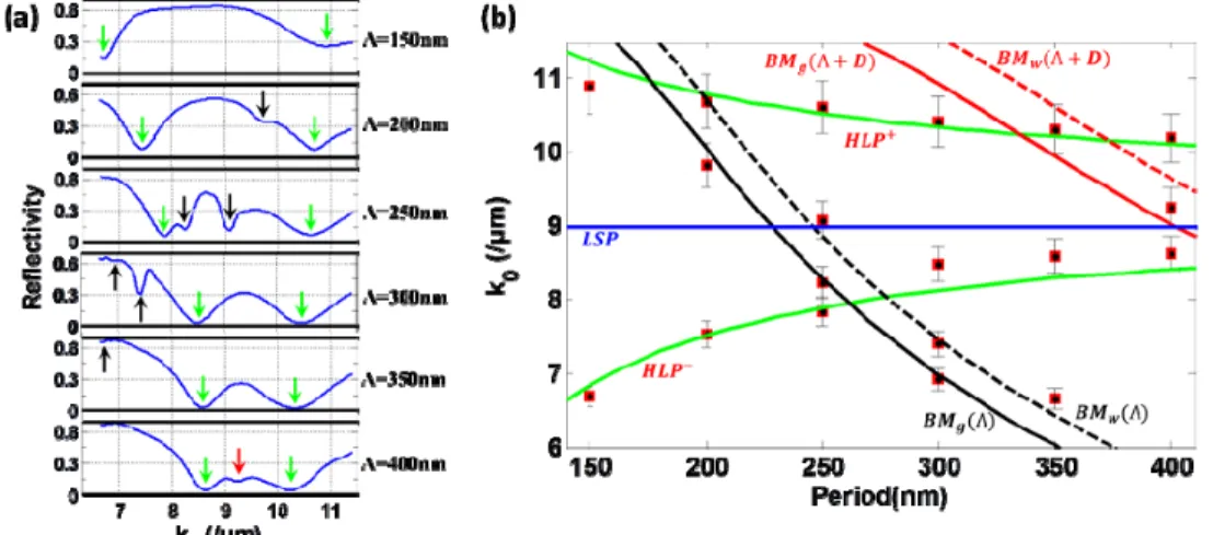
The results are summarized in Figure 8(a) where we have shown the normalized reflectivity (TM reflectivity divided by TE reflectivity) spectra for each period (Λ) at an incidence angle (θ) of 71.14°, and corresponding to a value of neff = 1.43. The different minima of reflectivity observed experimentally are related to the various modes excited in the structure. The resonance frequencies (reflectivity minima) of the different modes are shown as a function of period in Figure 8(b). This is similar to the results discussed in section 4.1. As in Figure 4, we have also plotted the analytically calculated dispersions as a function of period for the HLP and the BMs. For the analytical
calculation of the HLP, the coupling parameter was kept at the value of κ = (1/τ2)×(h
2+D)/Λ with τ = 0.37 fs as used
before. The experimental resonance frequencies are in close agreement with the analytically calculated dispersions for all the modes.
Fig 8. (a) Normalized reflectivity spectra at θ = 71.14° for different period (Λ) of the structure. Arrows show the reflectivity minima, which correspond to the various modes excited in the structure. (b) The resonance frequencies (k0) of all the modes (minima of reflectivity) are shown as
red squares as a function of array period. The error bars correspond to the minimum step of incident wavelength (10 nm) used for the experiment. We have superposed the analytically calculated frequencies of the modes as a function of period: LSP (blue), HLP (green), BMs calculated for kB
= 2π/(Λ) (black solid and dashed) and BMs for kB = 2π/(Λ+D) (red dashed and solid).
6. Conclusion
We have studied in details an array of gold nanocylinders with an underlying thin gold film in TM configuration. We have analytically calculated the LSP resonance frequencies for nanocylinders on a metallic substrate with the electric field parallel to the cylinder axis. We demonstrated that the resonance frequencies of the LSP mode, in this
configuration, decrease rapidly with increasing height (h2), while increase slightly with increasing diameter (D),
which is opposite to the expected trends in arrays on a glass substrate. For values of neff = k0/kx > nw, we can have a
coupling between the LSP mode of the cylinders, and the PSP mode of the gold film. This HLP mode dispersion was calculated using a model based on harmonic coupling of two oscillators. The coupling parameter dependency on
the structure dimensions is given by κ = (1/τ2)×(h
2+D)/Λ with τ = 0.37 fs. This was obtained by fitting the proposed
analytical model to rigorous numerical calculations. The existence of Bragg modes (BM) is also shown, which appears in the dispersion map as weak extinctions below the critical angle, and as bandgaps above the critical angle. Reflection and transmission characteristics of the modes in the Kretschmann configuration are also shown. Finally, this analytical model was experimentally confirmed by SPR measurements on nanostructurated samples fabricated
The proposed analytical model can accurately calculate the resonance frequencies of the various modes of the system. The model also offers a complete physical understanding of the modes present in such a structure. The HLP
mode is highly tunable with structural parameters such as diameter D and height h2 while the BM depends solely on
the periodicity Λ of the array. Similar structures are widely used for SERS and SPR biosensors, and the HLP mode can help to increase the sensitivity of such detection systems. Other modes, such as the BM, can prove to be useful to confine the electromagnetic field at nanometric scales around metallic nanoparticles. Thus, the proposed analytical model can help to optimize such structures for various applications.
Acknowledgements. This work is supported by the IDI 2012 project funded by the IDEX Paris-Saclay
(ANR-11-IDEX-003-02), ANR P2N (ANR-12-NANO-0016), CNANO IDF as well as LUMAT for partial funding of the project. IOGS/CNRS is also part of the European Network of Excellence in BioPhotonics: Photonics for Life (P4L).
APPENDIX
Numerical Simulations. The electric and the magnetic fields can be calculated for periodic structures using the
matrix formulation of FMM. As shown elsewhere a two-dimensional array can be sliced along the plane parallel to the array, and the electric and magnetic fields along each slice can be related to the adjoined slice by the S-matrix.[48] This gives stable results with reasonable computational speed and memory requirements. However, FMM formulation is not suitable for complex structure geometry particularly involving metallic media, and leads to a convergence problem. FEM can overcome this problem by using a fine mesh to represent the structure geometry. However, for very large structures a complete FEM calculation consumes enormous amount of memory and computational times. The in-house code developed in Matlab for this work, calculates the S-matrix (or related matrices that relates the electromagnetic fields at different slices along z-axis as shown in Figure 1) using FEM for the nanostructured section of the geometry. Then, using the matrix formulation of FMM, we can relate the fields calculated around the nano-structures, to the far-field transmission (T) and reflection (R) of the complete array. The absorption (A) of the system was also calculated as a function of incident frequency (ω) and in-plane wave-vector
(kx). This hybrid method can give accurate results, which have been verified by experiments here and in our recent
publications.
Nanostructure fabrication. The gold nanocylinder array was fabricated by electron beam lithography to assure
homogeneity, and have stable control of the size and shape of nanostructures over a large area (500 × 500 µm2).
After a cleaning step of BK7 using a Piranha solution (blend of sulfuric acid (H2SO4) and hydrogen peroxide
(H2O2)), the gold film (height h1) was deposited by electron beam evaporation (EBE) on a thin layer of titanium (2
nm), which is used as adhesion layer. For the e-beam lithography step, a layer of polymethylmethacrylate A2 (PMMA A2) is exposed at a current of 1.8 to 2.2 nA with different dose. A solution of methylisobutylketone and
isopropanol is used to develop the PMMA and gold nanocylinders (height h2) were deposited by another step of
EBE. The sample was totally cleaned by acetone in order to remove the resist, and in O2 plasma to remove other
residues. The film heights were measured by ellipsometry-spectroscopy and X-ray measurements with a relative
uncertainty under 10%. The measured gold film height h1 = 31 nm, and that of gold nanocylinders h2 = 32 nm.
In the Figure 7(c), we have presented the SEM images for several areas of nanocylinders with periodicities of 150 nm, 250 nm, and 400 nm. A mean diameter of around 53 ± 3 nm was found for the small periodicity (150 nm) by statistical analyses of SEM image treated with the Otsu’s method in order to extract the diameter of each nanostructure. For larger periods, due to the limited proximity charge effect during the e-beam lithography process, the mean diameter is around 51 ± 3 nm and closer than the simulated dimension of 50 nm.
Experimental setup. The SPR imaging system is based on a spectral scanning modality and the details have been
previously reported[49] [50] and is shown in figure 7(a). The incident wavelength (λ) from a halogen lamp used as the white light source, was varied within a range of 550 nm to 1000 nm with steps of 10 nm using a motorized monochromator (iHR 320, HORIBA Scientific). A motorized polarizer was used to switch between TM and TE polarization of the incident beam. The angle of incidence (θ) was varied within the range of 63-78° (internal angle at
the prism/structure interface) with steps of 0.5°, which corresponds to the range of neff = ngsinθ = 1.35-1.48. The
structure was placed in a micro-flow cell containing water with dimensions of 1 cm in diameter and 90 µm in depth, and the temperature in the flow-cell was controlled with a precision of 0.01°C. The light after reflection from the
structure was imaged using a CCD camera (Pixelfly QE, 1280×1024 pixels with a full well capacity of 18000 e-).
Four TM and TE images were acquired and averaged. The normalized reflectivity was calculated by dividing the TM images by TE images. The acquisition was controlled using a home-made Labview program.
Complete absorption and reflectivity dispersion maps.
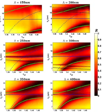
Figure A1. The normalized absorption (A) dispersion maps calculated by numerical methods with varying period (Λ) as a function of k0 and neff
for h2=30nm, D=50nm. The analytically calculated dispersion of the various modes is also shown which fits accurately to the rigorously
calculated numerical results.
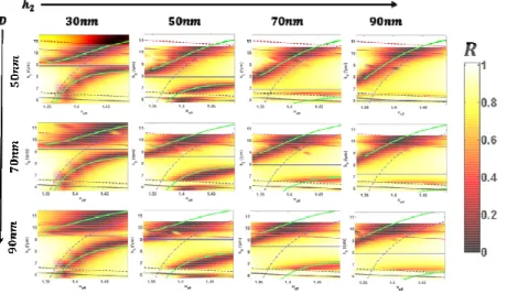
Figure A2. The normalized reflectivity (R) dispersion maps calculated by numerical methods with varying h2 and D function of k0 and neff for
Figure A3. The normalized reflectivity (R) dispersion maps obtained experimentally with varying period (Λ) as a function of k0 and neff for