Comparative Study of Bracing Patterns and Materials for
Tall Timber Buildings
by
Alexandra Kawar
B.S. Civil and Environmental Engineering University of Illinois at Urbana-Champaign, 2019
Submitted to the Department of Civil and Environmental Engineering in partial fulfillment of the requirements for the degree of
Master of Engineering in Civil and Environmental Engineering
at the
Massachusetts Institute of Technology
May 2020
© 2020 Alexandra Kawar. All rights reserved.
The author hereby grants to MIT permission to reproduce and to distribute publicly paper and electronic copies of this thesis document in whole or in part in any medium now known or
hereafter created.
Signature of Author:……….. Alexandra Kawar Department of Civil and Environmental Engineering May 8th, 2020
Certified By:……….. Gordana Herning Lecturer, Department of Civil and Environmental Engineering Thesis Supervisor
Accepted By:……….... Colette L. Heald Professor of Civil and Environmental Engineering Chair, Graduate Program Committee
Comparative Study of Bracing Patterns and Materials for
Tall Timber Buildings
by
Alexandra Kawar
Submitted to the Department of Civil and Environmental Engineering on May 8th, 2020 in Partial Fulfillment of the Requirements for the Degree of Master of Engineering in Civil and
Environmental Engineering
Abstract
Exploration of new designs for urban environments is increasingly focusing on reducing carbon emissions generated by construction and operation of tall buildings. With recent technological advances in timber construction and its potential to mitigate the carbon embodied in structural materials, tall timber buildings are gaining acceptance as various forms are considered for their designs. Recently built and proposed buildings demonstrate the use of mass timber to resist gravity and lateral loads. There are inherent efficiencies in placing lateral load resisting systems on the perimeter of a structure along with the possibilities to integrate versatile geometric patterns and effective structural solutions. However, timber material properties may lead to elements of larger volume than those made of steel or concrete. This study compares structural stiffness gains and carbon emission reductions for exterior bracing created in timber and timber-steel hybrid configurations. Numerical analyses are used to explore braced frame geometries and layouts for the steel and timber elements, to predict structural response, and compare the effects of material placement.
Thesis Supervisor: Gordana Herning
Acknowledgements
First, I would like to thank my family; I would not have made it to graduate school without the unwavering support from my parents throughout my educational career.
I would also like thank my incredible thesis advisor Gordana Herning. Her passion for structural engineering inspired me to push my research beyond what I thought was possible. Her patience and continuous support of my ideas made writing this thesis truly enjoyable.
Thank you to the additional Course 1 professors, especially Caitlin Mueller and Josephine Carstensen for their support and inspiration throughout the year.
Lastly, I would like to thank all of the students in the Course 1 Master of Engineering program. It was a pleasure to be constantly surrounded by a group of brilliant, motivated, and kind students.
Table of Contents
List of Figures….……….6
List of Tables….………..9
1 Introduction..………10
1.1 Motivation: Tall Timber Structures………...10
1.2 Challenges and Knowledge Gaps………..12
1.3 Opportunities for Design, Construction, and Environment………...13
1.4 Problem Statement………...15 1.5 Thesis Structure……….15 2 Literature Review………...16 2.1 Mass Timber………..16 2.1.1 Sustainable Forests………...17 2.1.2 Material Properties………...18 2.1.3 Fire Resistance ……….……...22 2.1.4 Connections………22
2.2 Exterior Systems for Tall Buildings………..23
2.2.1 Exterior Systems for Tall Timber Buildings………..25
2.3 Diagrid Systems………...27
2.4 Alternate Geometries………...29
3 Steel Diagrid Case Study………...31
3.1 Analysis of the Hearst Tower………31
3.1.1 Steel Hearst Tower Model………...32
3.2 Timber diagrid………...35
3.2.1 Timber Hearst Tower Model………...35
4 Alternate Geometries for Timber LFRS………..38
4.1 Topology Optimization………..38
4.2 The Timber Mega Brace………41
5 Hybrid Systems………44
5.1 RFEM Model Definition………45
5.2 One Bay Hybrid Layout………...45
5.3 Multiple Bay Hybrid Layout………..54
5.3.1 Critical Comparative Analysis………...59
5.4 Analysis………...61 5.4.1 Member Analysis………...61 5.4.2 Node Analysis………67 6 Results………..70 6.1 Stiffness………...70 6.2 Embodied Carbon………..70 7 Conclusion………...75 8 Future Work……….76 9 References………....77
Appendix A: Wind Loading………...82
Hearst Tower……….82
List of Figures
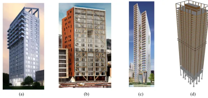
Figure 1: (a) Treet (b) Mjøstårnet (c) River Beech Tower (d) Timber Tower Research Project Figure 2: Carbon Dioxide Emissions (tons) to Air from Corresponding Material (Mendoza Beltran et al., 2018)
Figure 3: Three Principal Axes of Timber Figure 4: The Modulus-Density Chart
Figure 5: (a) Glued-Laminated Timber Beam (b) Connection from Tamedia Office Building (Didier Boy de la Tour, 2013)
Figure 6:Cross Section of Member Subject to Fire (American Wood Council, 2016)
Figure 7: (a) Jackson Hole Airport (Gensler, 2015) (b) Swatch Headquarters (Structurae, 2019) Figure 8:Lateral Force Resisting System Options (Sohail, 2013)
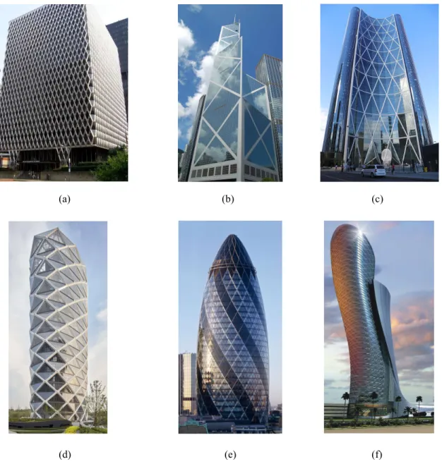
Figure 9: Unit Cost Index versus Number of Stories of a Structure (Khan, 1972) Figure 10:(a) Dewitt Chestnut Apartments (b) John Hancock Center (c) Willis Tower Figure 11: (a) “Treet” Structural System (Malo et al., 2016) (b) Mjøstårnet Structural System (Abrahamsen, 2017)
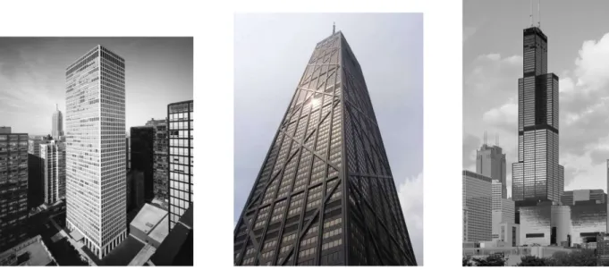
Figure 12:(a) United Steelworkers Building (b) Bank of China Tower (c) The Bow (d) Poly International Plaza (e) 30 St. Mary Axe (f) Capital Gate Tower
Figure 13: Load Transfer in a Diagrid System (Singh et al., 2014) Figure 14: CCTV Building
Figure 15: Structural Patterns Inspired by Nature (Skidmore, Owings, and Merrill LLP., 2011) Figure 16: (a) The Hearst Tower (b) Module of a Diagrid Structure (Asadi et al., 2018)
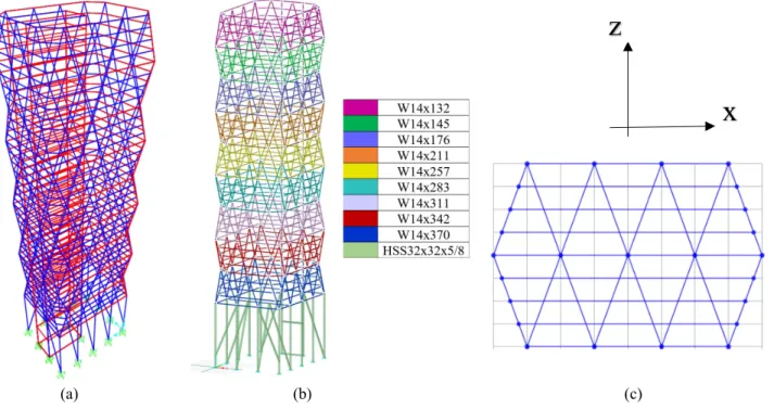
Figure 17: (a) SAP2000 18 Hearst Tower Model (b) W-Section Sizes of Each Module (c) Module Detail
Figure 18: Hearst Tower Typical Office Floor Layout (Rahimian and Eilon, 2008) Figure 19: X-Steel Model of Corner Node Connection (Rahimian and Eilon, 2008) Figure 20: Timber Hearst Tower Models
Figure 21: (a) Diagrid Subject to Asymmetric Overload Force (b) Axial Forces in Members Due to Overload Force
Figure 22: Topology optimization Design Problem Set-Up
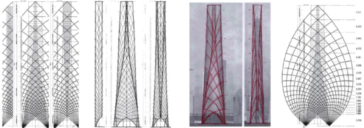
Figure 23: Optimized Solutions for the Steel (left) and Timber (right) Design Problem Figure 24: Two Braced Frame Topologies Using the High Waisted Brace Concept
List of Figures (cont.)
Figure 25: Building Geometry for Braced Frame Topologies shown in Figure 24 (a) Typical Floor Plan at Section 1 (b) Typical Floor Plan at Section 2 (c) Overall Dimensions
Figure 26: Applied Wind Loading (kip/feet)
Figure 27: Various Layouts for One Bay of the High Waisted Brace (Gray=Steel, Orange=Timber)
Figure 28: Deflected Shape of One Bay Layout
Figure 29: Embodied Carbon of Structures from Figure 27 Figure 30: Stiffness of Structures from Figure 27
Figure 31: Stiffness vs. Total Weight of Structures from Figure 27 Figure 32: Stiffness vs. Embodied Carbon of Structures from Figure 27
Figure 33: Normal Forces in Bottom Module Members of Figure 27(a) versus 27(b) Figure 34: Normal Forces in Bottom Module Members of Figure 27(a) versus 27(c) Figure 35: Normal Forces in Bottom Module Members of Figure 27(a) versus 27(d) Figure 36: Bending Moments in Bottom Module Members of Figure 27(a) versus 27(b) Figure 37: Bending Moments in Bottom Module Members of Figure 27(a) versus 27(c) Figure 38: Bending Moments in Bottom Module Members of Figure 27(a) versus 27(d)
Figure 39: Various Layouts for 3 Bays of the High Waisted Brace (Gray=Steel, Orange=Timber) Figure 40: Embodied Carbon of Structures from Figure 39
Figure 41: Stiffness of Structures from Figure 39
Figure 42: Stiffness vs. Total Weight of Structures from Figure 39 Figure 43: Stiffness vs. Embodied Carbon of Structures from Figure 39
Figure 44: Normal Forces in Bottom Module Members of Figure 39(a) versus 39(b) Figure 45: Normal Forces in Bottom Module Members of Figure 39(a) versus 39(c) Figure 46: Normal Forces in Bottom Module Members of Figure 39(a) versus 39(d) Figure 47: Bending Moments in Bottom Module Members of Figure 39(a) versus 39(b) Figure 48: Bending Moments in Bottom Module Members of Figure 39(a) versus 39(c) Figure 49: Bending Moments in Bottom Module Members of Figure 39(a) versus 39(d) Figure 50: Example (a) Member Design Location and (b) Cross Section
List of Figures (cont.)
Figure 52: (a) Typical Node Detail for Poly International Plaza (b) Proposed Node Design (Kim, 2010)
Figure 53: Node from Figure 36(b) Layout
Figure 54: Mechanical Connection Options for Glulam Members (LEERS WEINZAPFEL ASSOCIATES, 2017)
Figure 55: Jackson Triggs Estate Winery (KPMB Architects) Figure 56: Stiffness vs. Total Weight of All Structures Figure 57: Stiffness vs. Embodied Carbon of All Structures
List of Tables
Table 1: Different Mass Timber and Engineered Wood Products (Think Wood, 2015) Table 2: Material Properties of Various Softwoods and Hardwoods (ANSI/AWC NDS-2018) Table 3: Material Properties of Steel A36 and Steel A992 (ANSI/AISC 360-16:2016)
Table 4:Results of the One Bay Hybrid Layouts Table 5:Results of the Three Bay Hybrid Layouts Table 6:Material Data for 30F-2.1E SP
Table 7: Internal Forces of 8 Members Connecting into Node Represented in Figure 47 Table 8. Three-Dimensional View of All Structures
Chapter 1
Introduction
1.1 Motivation: Tall Timber Structures
According to the United Nations recent world population report, we are expected to reach a population of 9.7 billion by the year 2050. With 68% of the population predicted to live in urban areas, we need to sustainably build taller to account for the increasing density of cities (United Nations, 2018). Currently, steel and cement are the top two contributors to carbon emissions in China, which is one of the largest manufacturing and construction markets in the world (Hough, 2019). Timber has the ability to sequester CO2: timber products lock approximately 1 ton of
CO2 per 1 m3 of wood. It is an appealing alternative material choice considering that climate change is largely due to greenhouse gas emissions. Timber is not a novel building material; it was used for hundreds of years prior to the industrial revolution. Around 1880, the second industrial age introduced steel as a new building material due to its high strength-to-weight ratio and ductility, allowing for taller buildings to be constructed. However, about 1.85 tons of CO2 is emitted with every ton of steel produced. Therefore, there is a need to discover how to build taller with a less harmful material.
Timber is mainly used for light wood-frame construction, but mass timber technology has the potential to be a competitive alternate material. Mass timber is a category of framing styles that uses large solid wood panels for roof, floor, and wall construction (Think Wood, 2015). These elements are engineered wood, which are wood products manufactured by binding pieces with adhesives or other methods of fixation. Mass timber buildings are gradually emerging in North America, but it has not been the preferred primary material choice for multi-story structures. This is due to several reasons; some of which include technical issues such as vibrations, or more broadly, regional standard practices in design, fabrication and construction. Building codes and material costs vary considerably across the globe.
Some notable existing timber structures include 58-meter Brock Commons Tallwood House in Canada, 84-meter HoHo Vienna, and 100-meter Pyramidenkogel Observation Tower in Austria. Two have been completed in Norway: Treet, a 14-story timber framed apartment building, and
Mjøstårnet, an 18-story timber mixed-use building, both of which are shown in Figure 1.
World renowned structural engineering firms are leading the way and increasingly incorporating timber into their design proposals and research projects. Thornton Tomasetti proposed the 80-story River Beech Tower shown in Figure 1(c). An in-depth study of the material properties of timber was conducted to find the most effective way to arrange the materials. The building uses cross-laminated timber shear walls, glued cross-laminated timber bracing, and cross-laminated veneer lumber diagrids to engage the vertical elements to resist the lateral loading and fully utilize the gravity elements (Sanner et al., 2017). Skidmore, Owings, and Merrill (SOM) developed their Timber Tower Research Project in which the existing Dewitt-Chestnut Apartment building is redesigned as a “Concrete Jointed Timber Frame.” In this structural system, mass timber is used for the main structural elements and concrete is used at the connecting joints which are the most highly stressed locations (SOM, 2017).
(a) (b) (c) (d)
Figure 1. (a) Treet (b) Mjøstårnet (c) River Beech Tower (d) Timber Tower Research Project
These completed structures and proposed designs, combined with advances in technology and environmental concerns, are contributing to the increasing interest in design that involves material and structural innovation, fabrication, construction advances, and new architectural forms.
structures, but timber does not behave in the same way as these materials. Instead of substituting timber into the typical design methodologies, we need to develop designs or structural systems for high rises that use timber optimally. The objective of this thesis is to study the performance of timber in the lateral systems of high-rise buildings and find the ideal placement for the main structural materials, namely timber and steel.
1.2 Challenges and Knowledge Gaps
Despite the environmental advantages of tall mass timber buildings, few are in existence due to the many technical challenges involved in building with engineered wood. Timber is less dense than concrete: it has a density of roughly 37 pounds per cubic foot compared to 150 pounds per cubic foot for concrete. Because of this, airborne and impact sounds travel easier through the material. This presents acoustical and vibration challenges with the construction of residential and commercial buildings. For example, a typical concrete floor slab has a fundamental natural frequency less than 9 Hz, and bare cross-laminated timber floors have a fundamental natural frequency of higher than 9 Hz (Hu and Gagnon, 2012). A higher natural frequency material is more responsive to dynamic loading such as occupant movement, making it difficult to control vibrations in timber floors and creating a significant occupant comfort issue. Additionally, the lightweight nature of the material causes it to drift more at greater heights compared to the drift of steel or concrete skyscrapers. Because of these challenges, a larger volume of wood or hybrid solution may be needed to achieve design requirements, which can make a timber building a more costly alternative to a steel or concrete structure. This added material cost is in addition to the construction and fabrication costs related to building with timber at greater heights.
Additionally, wood can absorb and release moisture with changes in the environment. The changes in the dimensions of the members is accounted for in the design, but protection of the members from weather during construction is very important so that the changes do not exceed allowable tolerances. Elevated moisture levels can cause dimensional instability, cracking, microbial attack, decay, mold, and faster corrosion (Kordziel et al., 2018). A related challenge to the potential shrinkage and swelling is creep, or the time-dependent mechanical behavior of timber. Timber is a viscoelastic material so its deformation response is a combination of both elastic and viscous components, and the viscous creep should be studied to understand the deformation with time
(O’Ceallaigh et al., 2016). There is also the possibility for complex loading such as biaxial, dynamic, or hazardous overload, and the behavior of timber in these events needs to be studied further. Early coordination between design and construction disciplines and proper scheduling are extremely important for building with mass timber.
Another area of timber construction that is lacking is connection design; connections are often the most critical part of a structure. Steel is frequently used for connecting members because of its strength and ductility, but more studies on the behavior of innovative timber connections at the local and global system levels are needed.
Currently, the International Building Code (IBC) allows for timber buildings in North America to reach up to six stories without requiring additional approval. However, changes are coming in the 2021 International Building Code to allow for up to 18 stories.
1.3 Opportunities for Design, Construction and Environment
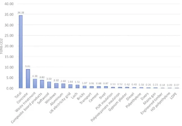
In addition to the challenges previously discussed, there are numerous opportunities and benefits to constructing with mass timber. For structural purposes, timber may be the most promising renewable building material with respect to its strength to weight ratio, stiffness to weight ratio, and other characteristics. The most significant benefit timber has is the lesser environmental impact it has compared to steel and concrete. Timber converts carbon dioxide to biomass through photosynthesis and sequesters it. Figure 2 shows various construction materials and their corresponding embodied carbon content in tons of carbon dioxide (Mendoza Beltran et al., 2018). Common tall building materials such as cement and steel have over 6 times the embodied carbon content to that of engineered timber.
Figure 2. Carbon Dioxide Emissions (tons) to Air from Corresponding Material (Mendoza Beltran et al., 2018)
Since engineered wood products are manufactured off-site, the construction process is accelerated once the materials arrive on site. There is no need for noisy and dangerous construction machines like jackhammers and cement mixers, so the construction process is quiet and safe. Another concern regarding building with timber is how it performs in the event of a fire. This presents an opportunity for further fire research and the modeling and testing of the mechanical behavior of the material under fire conditions. Exposed mass timber elements char on the outside which forms an insulating layer to protect the strength of the material on the inside. Additionally, the lightweight nature of the material presents a unique design opportunity to require less foundations and less forces for seismic resistance.
Lastly, timber provides infinite opportunities in the design process and exposing the material aids in occupant comfort and well-being. Living in dense, urban cities surrounded by skyscrapers can be stress inducing, and there is growing evidence that biophilic design can counter this type of stress. Visual, tactile, and olfactory responses to natural materials lower stress levels as measured by blood pressure, pulse rate, skin conductance, muscle tension, and electrical activity of the brain
(Grinde and Patil, 2009). Exposing the structural elements requires close collaboration between the engineer and the architect from the onset of the design process which may result in more integrated and holistic qualities of the structure.
1.4 Problem Statement
The aim of this thesis is to evaluate the efficiency of various configurations for exterior structural systems resisting lateral loads in tall mass timber buildings. Timber diagrids and exterior braced frames will be assessed by analyzing steel, timber, and hybrid steel-timber configurations. Ultimately, an attempt is made to evaluate and understand the behavior of lateral systems for tall timber structures. Finding effective exterior lateral force resisting systems (LFRS) for multi-story timber buildings would ideally result in versatile architectural forms that are based on principles of structural action and reduced use of materials. This will aid in constructing taller timber buildings to accommodate for the needed living space without having a large environmental impact.
1.5 Thesis Structure
The following chapter presents a discussion of mass timber elements and their properties, lateral systems for both steel and timber buildings, and alternate geometries for lateral systems. Chapter 3 begins with a study of the Hearst Tower and a numerical analysis of the building using SAP 2000 (CSI, 2018). Next, the Hearst Tower is modeled using RFEM (Dlubal, 2020) with the main structural material changed to timber. In Chapter 4, a topology optimization problem was solved using MATLAB and the resulting form was used to formulate concepts for exterior bracing layouts, some of which were inspired by the Baker Brace (Johnson, 2020). Chapter 5 explores various forms of steel-timber hybrid systems and the structural behavior of these systems. The member sizes were optimized, and the weight, deflection, and embodied carbon of each model was compared. A representative member and selected node of the structure were chosen and analyzed. The timber and hybrid configurations were evaluated in depth to assess the impact that geometry and material placement have on structural performance and embodied carbon emissions.
Chapter 2
Literature Review
In this chapter, an overview of the different types of construction and engineered wood products are discussed in-depth. Where structural timber is harvested, how it behaves compared to other materials, and the current fire protection practices are discussed. Section 2.2 explains the different lateral force resisting systems for buildings and those specifically for timber. Section 2.3 discusses diagrid systems and section 2.4 describes the unlimited potential for geometric layouts of materials and opportunities for efficient design solutions.
2.1 Mass Timber
The American Wood Council defines heavy timber as structural glue-laminated timber or sawn lumber associated with Type IV construction. The current IBC contains five construction types, and four of them have sub-types. These categories of construction have defined maximum allowable heights, fire resistance and safety requirements. The 2021 IBC will allow for timber buildings to reach up to 18 stories by adding three new construction types: Type IV-A, IV-B, and IV-C, and rename Type IV to IV-HT.
Heavy timber includes mass timber, which is large, solid wood panels used for wall, roof, and floor construction. Common products categorized as mass timber include cross-laminated timber (CLT), dowel-laminated timber (DLT), glued-laminated timber (glulam), laminated strand lumber (LSL), laminated veneer lumber (LVL), mass plywood panel (MPP), nail-laminated timber (NLT), and parallel strand lumber (PSL) (Think Wood, 2015). These can all be seen in Table 1.
Table 1. Different Mass Timber and Engineered Wood Products (Think Wood, 2015)
Cross-Laminated Timber
(CLT)
3, 5, or 7 layers of lumber oriented at right angles and glued together
Dowel-Laminated Timber
(DLT)
Individual dimension lumber stacked on edge and fastened with wood
dowels
Glued-Laminated Timber (glulam)
Dimension lumber bonded together with
moisture-resistant adhesives
Laminated Strand Lumber
(LSL)
Soft wood or wood strands pressure-bonded
together using water-resistant adhesive Laminated
Veneer Lumber (LVL)
Layered dried and graded wood veneers, strands, or
flakes with moisture resistant adhesive
Mass Plywood Panel (MPP)
Several layers of wood veneer glued and pressed
together to form a large wood panel
Nail-Laminated Timber
(NLT)
Individual dimension lumber stacked on edge and fastened using nails into a single element
Parallel Strand Lumber
(PSL)
Flaked wood strands formed into large billet
using waterproof adhesive and then cured
2.1.1 Sustainable Forests
A common misconception about using wood as a construction material is that the large volume of wood needed would lead to deforestation. However, using the wood from a sustainably managed forest is very beneficial for the forest. As trees grow, they absorb carbon dioxide and release oxygen into the atmosphere. Young trees take up carbon much quicker than mature trees (60-100 years old), and as trees get older, there are three possible outcomes for them. The first is that they
start to decay and slowly release the stored carbon into the atmosphere. Another possibility is that the forest is subjected to wildfire, disease or insects that causes the stored carbon to be released. Lastly, the trees can be harvested and manufactured into products that continue to store the carbon. This is the best option because in wooden buildings the carbon is kept out of the atmosphere for the lifetime of the structure or potentially longer, if the wood is reused or remanufactured into other products at the end of the building life (Ward, 2019). Additionally, wood requires less energy overall to manufacture, and the ability for timber to sequester carbon significantly decreases the embodied carbon of a structure compared to other common buildings made from steel and concrete.
2.1.2 Material Properties
The material properties of timber differ greatly from steel and concrete, and several changes in the design process must be accounted for. First, steel is an isotropic material- one that behaves in the same manner independent of the direction the load is applied. On the other hand, an anisotropic material is dependent on the direction the load is applied. The physical properties of the material will differ in various directions. Timber is an orthotropic material, which is a subset of anisotropic materials. Orthotropic materials have three planes or axes of symmetry. For timber, these mutually perpendicular axes include the longitudinal, tangential, and radial directions shown in Figure 3.
Figure 3. Three Principal Axes of Timber
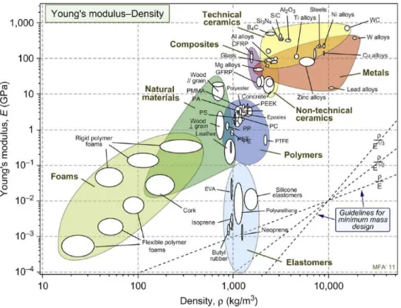
Because of the varying strengths in the differing directions, there are several moduli of elasticity, as opposed to just one when designing with steel. Figure 4 shows the modulus-density chart, which makes it easier to select materials to minimize the mass of stiffness-limited structures (Ashby, 2013). The chart shows that the stiffness of wood parallel to the grain is close to concrete, although
it is less dense. Wood both parallel and perpendicular to the grain are less stiff and less dense than steel.
Figure 4. The Modulus-Density Chart
The modulus of elasticity for the different axes of timber depend on the species of wood chosen, which usually depends on the material availability in the area. Table 2 shows the material properties of various softwoods and hardwoods available for design. Hardwoods are not as strong as softwoods but can still be appropriately placed and used in construction of mass timber structures. Figure 5(a) shows the different layers of a glulam beam; it is typical to have lower grade material near the neutral axis and higher grade material at the outer laminations so strength goals can still be achieved while not having to only utilize the highest grade timber. Additionally, Figure 5(b) shows a connection design from the Tamedia Office Building where pure timber connections are used to avoid compression perpendicular to the grain at horizontal joints. This oval shape connection produces a rigid grip that alleviates the stresses that the spruce wood at that location could not withstand (Cohn, 2014).
(a) (b)
Figure 5. (a) Glued-Laminated Timber Beam (b) Connection from Tamedia Office Building (Didier Boy de la Tour, 2013)
The timber chosen for the design and analysis in this paper is 30F-2.1E SP Softwood, 4 to 15 lams at various sizes. 30F represents the strength of the bottom of the beam in tension is 3000 psi, 2.1E means the modulus of elasticity for deflection calculations is 2.1 x 10 psi, and SP stands for Southern Pine. This material was chosen from NDS Supplement Table 5A. The design procedure in NDS accounts for changes in the strength and stiffness of timber due to temperature and moisture changes (temperature factor and wet service factor).
The effects of timber’s dimensional expansion and contraction on connections are considered to avoid unwanted internal stresses. For comparison, Table 3 shows the material properties of common steel material options, A36 and A992. It is evident that all the material properties of steel are higher than timber proving it is stronger and stiffer. Therefore, there are certain parts of the structure where different materials can be appropriately placed based on their properties. For example, steel is a great material choice for the connections, the most critical part of the structure, due to its high tensile strength and ductility.
Table 2. Material Properties of Various Softwoods and Hardwoods (ANSI/AWC NDS-2018)
Table 3. Material Properties of Steel A36 and Steel A992 (ANSI/AISC 360-16:2016) 30F Southern
Pine Visually Graded Western Species Hardwoods, 12F Visually Graded Visually Graded Hardwoods, 20F
Wood Category Softwood Softwood Hardwood Hardwood
Combination Symbol General 75 12F-V1 20F-V1
Reference Modulus of Elasticity
(Axial Loading) Ez 1785 1785 1050 1470 ksi
Reference Shear Modulus (Axial
Loading) Gz 111.563 111.563 65.25 91.875
ksi Reference Modulus of Elasticity
(Loading Perpendicular to Wide Faces
of Lams) E
x 2100 1700 1200 1700 ksi
Reference Shear Modulus (Loading
Perpendicular to Wide Faces of Lams) Gx 131.25 106.25 75 106.25 ksi Reference Modulus of Elasticity
(Loading Parallel to Wide Faces of
Lams) E
y 1700 1700 1000 1400
ksi Reference Shear Modulus (Loading
Parallel to Wide Faces of Lams) Gy 106.25 106.25 62.50 87.5 ksi Modulus of Elasticity Perpendicular E90 70 56.67 40 56.67 ksi Shear Modulus Perpendicular G90 13.125 10.625 7.5 10.625 ksi Reference Tension Design Value
Parallel to Grain Ft 1.25 1.35 0.6 1.0 ksi
Reference Compression Design Value
Parallel to Grain Fc 1.75 2.3 0.8 1.4
ksi Reference Bending Design Value
(Bending Perpendicular to Wide Faces
of Lams) F
bx 3 1.85 1.2 2.0
ksi Reference Bending Design Value
(Bending Parallel to Wide Faces of Lams)
Fby 1.75 1.95 1.05 1.7
ksi Reference Shear Design Value
Parallel to the Grain Fvx 0.3 0.265 0.125 0.2 ksi
Reference Shear Design Value
Parallel to the Grain Fvy 0.26 0.230 0.110 0.175 ksi
Specific Gravity G 0.55 0.46 0.39 0.63
Specific Weight γ 39.90 31.20 26.70 41.80 lbf/ft
Coefficient of Thermal Expansion α 2.78E-06 2.78E-06 2.78E-06 2.78E-06 1/°F
Steel A36 Steel A992 Modulus of Elasticity E 29000 29000 ksi
Shear Modulus G 11200 11200 ksi
Poisson’s Ratio ν 0.300 0.300
Specific Weight γ 490.00 490.00 lbf/ft Coefficient of Thermal Expansion α 6.67E-06 6.67E-06 1/°F Yield Strength Fy 36.000 50.000 ksi Ultimate Strength Fu 58.000 65.000 ksi
2.1.3 Fire Resistance
All structural materials have inherent attributes that impact their behavior in fire and require specific protective measures to ensure structural stability long enough to allow evacuation of occupants. (Buchanan, 2017). Because it is often associated with fueling a fire, timber is assumed to be more susceptible to fire damage. However, it is much more difficult to ignite mass timber elements rather than small logs and there are several methods to protect these elements that have been tested and proven to be safe. One method to increase the fire resistance of mass timber elements is to encapsulate them in another material. As long as the wood inside is properly protected, no change is needed for the design of the member. Another method for fire resistance is to increase the cross-section of the member and take advantage of timber’s ability to create a char layer on the outside. NDS Chapter 16 specifies a char calculation method that accounts for the ability that heavy and mass timber elements have to form a char zone that insulates the remaining wood cross-section and allows it to retain the structural capacity. According to NDS Table 16.2.1A, the effective char rate is about 1.5 inches per hour. Figure 6 shows the initial cross section dimensions D x B, and the remaining size of the member that retains the structural capacity, d x b.
Figure 6. Cross Section of Member Subject to Fire (American Wood Council, 2016)
2.1.4 Connections
Proper connection design is critical for building performance; structural failures during extreme events are often due to faults in connection assembly or design (ReThink Wood). Some important
things to note when designing connections for wood is that wooden connections are stronger when the load is spread over several fasteners, and wood is affected by moisture. It is advised to use multiple small fasteners with a size relative to the size of the wood members being connected, and allowances must be made to account for possible swelling and shrinkage. The two major types of connections include mechanical (dowel, metal connector plates, and shear) and joinery (interlocking members through notches or holes). One example of a mechanical connection is shown in Figure 7(a): in the Jackson Hole Airport, diagonal wood braces are connected to the beams with embedded steel knife plates and structural screws.
(a) (b)
Figure 7. (a) Jackson Hole Airport (Gensler, 2015) (b) Swatch Headquarters (Structurae, 2019)
Figure 7(b) shows the joinery connections of the Swatch Headquarters in Switzerland. All 4,600 beams were produced with great speed and precision using CNC milling. In North America, mechanical connections are more common because they usually do not require expensive equipment or expert assembly (reThink Wood).
2.2 Exterior Systems for Tall Buildings
As building height increases, wind and seismic lateral forces tend to govern the structural design and the lateral system choice becomes very important. Because tall buildings have large overturning moments, it is important to direct the vertical loads in the building into the lateral load resisting system and to position this system as close to the perimeter of the building as possible (Ramage et al., 2017). Classic lateral force resisting systems for buildings include shear walls, braced frames, and moment frames; these can be seen in Figure 8. Shear walls are braced panels
that provide resistance by cantilever action. They are less efficient because there are no options for windows. Braced frames are stiff structural systems made of a series of diagonal members and can be located internally or externally. Moment frames are ideal for architectural design but can be the most expensive option because of the moment connections required to rigidly connect the beams and columns that resist the lateral loads.
Figure 8. Lateral Force Resisting System Options (Sohail, 2013)
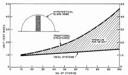
The lateral system of a building significantly contributes to the cost of the structure. Fazlur Khan explains that buildings have a “premium for height” which is the substantial penalty buildings taller than 10 stories must pay for being tall (Khan, 1972). Figure 9 shows how in an ideal system where a hypothetical glass dome would block all wind loading, the cost of the structure increases slightly as the number of stories increase. However in reality, the cost increases greatly with the number of stories proving the need to design an ‘optimal’ system for height- one that is most structurally and economically efficient for resisting lateral loads.
The lateral force resisting systems shown in Figure 8 are typically on the interior of the building; Fazlur Khan developed prominent exterior lateral force resisting systems: the framed tube, trussed tube, and bundled tube which can be seen in Figure 10. These tube systems use exterior elements that provide enough framing and bracing to resist lateral loads and reduce the amount of required interior structural elements. The Dewitt Chesnut Apartment building is a framed tube made of closely spaced exterior columns cantilevered from the foundation to resist lateral loads. The John Hancock Center is a trussed tube which uses diagonal bracing for a more even redistribution of loads. Lastly the Willis Tower is a bundled tube system made up of independently strong tubes that are further strengthened through truss connections (Adriaenssens and Garlock, 2011).
Figure 10. (a) Dewitt Chestnut Apartments (b) John Hancock Center (c) Willis Tower
Khan discusses the potential to eliminate the premium for height by devising alternate structural systems such as exterior framing similar to the John Hancock, but eliminating interior columns completely (Khan, 1972). There are many opportunities to explore various configurations to minimize this premium for height because when structures include more than one material (concrete, steel, timber, etc.) there are multiple objectives for structural, material, cost, construction, and CO2 efficiency.
2.2.1 Exterior Systems for Tall Timber Buildings
(LFRS), interconnectivity and compatibility between LFRS-to-gravity system, and potential hybridization of structural materials for the gravity system and LFRS (Sinha et. al, 2019). One example is the SOFIE project, where 3-story and 7-story CLT buildings were tested to analyze the behavior of connections and CLT wall panels under monotonic and cyclic loading. In this study it was experimentally demonstrated that the strength and stiffness of the CLT wall panels are heavily dependent on the behavior and location of the connectors (van de Lindt, 2013). In timber multi-story buildings, lateral systems can be all timber (e.g. CLT cores or shear walls) or they can be made of other materials to create a hybrid structure. “Treet”, the 14-story timber residential building in Norway has glulam trusses along the facades of the building to achieve the necessary stiffness. Similarly, the 18-story timber building Mjøstårnet uses these large glulam trusses; both can be seen in Figure 11. The proposed River Beech Tower uses CLT shear walls, GLT bracing, and LVL diagrids to engage the vertical elements and resist lateral loads (Sanner et al., 2017). The goal with this project, and many like it, is to arrange the materials for maximum effectiveness. A lateral stability system that places the bracing on the building façade channels the weight of the tower into the façade and bracing systems which accommodates for the lightweight nature of timber (Ramage et al., 2017). This paper aims to study the various placement of timber and other materials to achieve desired strength and stiffness.
(a) (b)
2.3 Diagrid Systems
(a) (b) (c)
(d) (e) (f)
Figure 12. (a) United Steelworkers Building (b) Bank of China Tower (c) The Bow (d) Poly International Plaza (e) 30 St. Mary Axe (f) Capital Gate Tower
A structurally advantageous and aesthetically pleasing system that has been used for many years is the diagrid, which lies on the exterior of the structure. Figure 12 shows several prominent existing diagrid structures. A diagrid is a lateral force resisting system made of diagonally placed elements to provide extra stiffness with less material usage. The load transfer in a simplified
version of a diagrid system can be seen in Figure 13. Providing lateral resistance on the outside can help reduce the size of a core or even accommodate for an offset core. Additionally, it has been proven that any configuration of a diagrid building experiences less shear lag effect than the framed tube building. Shear lag is a nonlinear distribution of stresses across the sides of a section which results in higher stresses at the corner columns than the inner columns of the sides of box girders (Leonard, 2007).
Figure 13. Load Transfer in a Diagrid System (Singh et al., 2014)
Diagrid element patterns can also be adapted based on the force in structural members. For example, in the CCTV building shown in Figure 14, the density of the diagonal elements changes along the height of the building to accommodate for higher element forces in the corresponding locations.
From an architectural standpoint, diagrid structures grew in popularity from the aesthetic appeal of the diagonally placed members. Moreover, these systems are equally as popular among engineers due to their structural efficiency. Structural efficiency may be defined as the ratio between the total mass of the structure and the load it can sustain. Because of the triangulated configuration, the diagonal members carry both gravity and lateral loads, and often do not require high rigidity shear cores (Jani and Patel, 2013). Additionally, more open floor plans can be adopted because there is less of a need for interior columns.
Analysis and design of box form diagrids was studied by Jani et al. (Jani and Patel, 2013) and further studies of more complex geometries were investigated by Moon, Connor, and Fernandez (2007). Another paper by Moon (2008) recommends optimal geometries for diagrid structures to meet stiffness requirements by using the least amount of material. With advances in technology and computational power, design alternatives can be compared more quickly and optimal layouts for diagrid structures can be found using parametric algorithms. Another study by Gerasimidis et al. (2016) was performed to optimize diagonal member sizes and choose the angle of these members to achieve the highest structural efficiency.
Mass timber buildings that are built at the present time do not take the form of a traditional diagrid or express the structural system on the façade of the building. This paper begins with an exploration of the feasibility of a classic diagrid system reimagined in mass timber. From there, alternate geometries are explored to assess the effect that material placement has on stiffness.
2.4 Alternate Geometries
Structural efficiency can be achieved through other geometries besides diagrids. Specifically, a paper by SOM discusses various configuration of elements inspired by the efficiency and adaptability of natural organisms (Skidmore, Owings, and Merrill LLP., 2011). Figure 15 shows examples of various geometries inspired by those found in nature such as the nautilus shell or a hurricane. The architect and engineer Pier Luigi Nervi explored the relationship between form, performance, and construction. He specifically focused on “organic” structures and how they conform to laws of physics and rules of efficiency in their growth patterns (Leslie, 2003). These examples expand the number of potential configurations of exterior elements for lateral resisting
systems.
Figure 15. Structural Patterns Inspired by Nature (Skidmore, Owings, and Merrill LLP., 2011)
Most of the previously discussed papers use steel as the material for the diagrid structure. This paper considers timber and timber-steel hybrid systems in the design of lateral systems. In the following discussion, various forms and geometries are modeled and analyzed in order to compare appropriate strength, stiffness, behavior, and embodied carbon for timber structures. This paper begins with the model and analysis of a classic steel diagrid, followed by a timber diagrid and the examination of other forms.
Chapter 3
Steel Diagrid Case Study
The objective of this paper is to examine the behavior of various configurations of lateral systems for tall timber structures. This chapter begins with a feasibility study of the Hearst Tower modeled with the main structural material being timber instead of steel. First, the Hearst Tower is modeled and analyzed in SAP2000 18 with steel framing. It is then modeled and analyzed in RFEM 5.22 with glulam timber elements. The models are compared, and a new height is proposed for the Hearst Tower if timber was chosen as the main material.
3.1 Analysis of the Hearst Tower
(a) (b)
Figure 16. (a) The Hearst Tower (b) Module of a Diagrid Structure (Asadi et al., 2018)
The Hearst International Magazine Building was built in 1928 by Joseph Urban. This 6-story building was designed in anticipation of adding a tower within the next few years, but the great depression delayed the construction. It was not until 2001 that Foster+Partners, WSP Cantor Seinuk, and Turner Construction joined to begin designing the tower. Because of the low ceilings and limited office space of the existing building, Foster decided to clear out the entire interior of the building to create a large atrium at the entry level. The new Hearst tower rises 46 stories above the existing 200x200 foot base, with a footprint of 160 by 120 feet and final height of 597 feet. Because it is placed right beside a building, the concrete core wall for the tower is shifted and
placed against the west face of the building. To accommodate for this offset core, a diagrid was chosen to provide stability and eliminated the need for perimeter columns. A detail of this system and an individual module can be seen in Figure 16(b) (Note: the Hearst Tower has 4 floors per module). Overall, the diagrid structure resulted in a 20 percent reduction in structural steel compared with a conventional moment frame (Fortner, 2006).
3.1.1 Steel Hearst Tower Model
The Hearst Tower was initially modeled in SAP2000 18 using the same steel W-sections used for the Hearst Tower as shown in Figure 17(b). 40-foot interior column free spans were utilized in the same fashion as the Hearst Tower with the same floor plan as shown in Figure 18. The dead loads include the self-weight of the exterior members, a 3-inch normal weight concrete floor with 3C16 metal decking, CMEP, floor finishes, and ceilings. Live loads assumed in the analysis include office loading and partitions and are consistent throughout the height of the building. The wind forces were applied as line loads at every floor of the largest side (controlling) of the structure; detailed wind loading calculations can be seen in Appendix A, according to Chapter 26 of ASCE 7-16.
A rigid floor surface is defined at each level creating a rigid connection between adjacent objects. The diagonals are connected at each floor. Four floor levels make up each triangular module as shown in Figure 17(c). The mega columns at the bottom of the tower that are surrounded by the old Hearst International Magazine Building are modeled with steel HSS sections. They have fixed connections at the base which restrain all six degrees of freedom: no displacement or rotation in the X, Y, or Z direction.
(a) (b) (c)
Figure 17. (a) SAP2000 18 Hearst Tower Model (b) W-Section Sizes of Each Module (c) Module Detail
Figure 18. Hearst Tower Typical Office Floor Layout (Rahimian and Eilon, 2008)
Viewing the tower in the X-Z direction as shown in Figure 17(c), the members are oriented with the web parallel to the façade, so the flanges are responsible for resisting bending. All hinge conditions were deactivated, meaning the connections are fully rigid and transfer moments. As
x
z
shown in Figure 19, the constructed nodes in the Hearst Tower diagrid and other similar diagrids are typically continuous.
Figure 19. X-Steel Model of Corner Node Connection (Rahimian and Eilon, 2008)
It is assumed that the concrete core inside the tower handles most of the lateral loading; it was offset in the same way it is positioned in the Hearst Tower. The exterior diagrid was modeled separately from the concrete core wall to determine what percentage of the wind load was resisted by the diagrid, and what percentage was resisted by the core wall. To ensure lateral drift compatibility, various percentages of the wind loading were applied to both structures. The separate structures drifted the same amount when 75% of the wind load was applied to the core wall and 25% was applied to the timber diagrid. Therefore, for the remainder of the analysis procedures only 25% of the wind loading is applied to the exterior element structures. Based on the review of case studies, this is similar to several other diagrid designs.
The steel model was analyzed using a lateral drift limit of h/500, with h being the overall height of the structure (ASCE, 1988). It should be noted that designers can impose an absolute limit on interstory drift because damage to nonstructural partitions, cladding, and glazing may occur if the interstory drift exceeds about 0.4 inches (ASCE 7-16). Given the Hearst Tower height of 597 feet, the drift limit is 14.33 inches. The SAP2000 model of the steel Hearst Tower had a drift of 10.78 inches.
3.2 Timber Diagrid
3.2.1 Timber Hearst Tower Model
The next step was to model this tower in RFEM 5.22, a 3D finite element software for structural analysis and design of steel, concrete, timber, glass, membrane, and tensile structures. It is easier to model timber structures in RFEM due to the large library of engineered wood and sawn lumber materials, rather than manually inputting the material properties of the desired material into another program such as SAP2000. The same grade of timber that was discussed in Chapter 2.1.2 and shown in Table 2 was used in this model.
The Hearst Tower model was imported into RFEM and the main structural element material was changed to timber. The gravity system is assumed to be CLT floor panels with interior columns spaced at an average of 25 feet, which is less than what was used for the steel Hearst Tower model, but is common for CLT floor panels. In RFEM, rigid floor surfaces are again defined at every level and connect all adjacent elements creating a rigid timber diaphragm. Similarly, 4 floor levels make up each triangular module.
The mega columns at the bottom of the tower are modeled in timber without the surrounding structure and have fixed connections at the base. Pin connections at the base of the structure may be used for constructability reasons; the model was checked using pin connections instead of fixed and the results were not affected. All loading remains the same as the steel model, except the dead loading for the CLT floor replaces the dead loading for the steel and concrete composite floor. The timber members listed as width x height have the height parallel to the façade in the vertical direction. All hinge conditions were again deactivated, providing moment connections at each node.
In order to comply with the lateral drift limit, 60 x 60-inch members had to be used for the exterior elements. However, the model was not optimized to find the minimal size required at each height. These member sizes were not adjusted to add extra material for fire safety and are most-likely far larger than desirable for elements that will be visible on the façade of a building. As discussed in section 2.1.3, exposed mass timber elements char on the outside at a rate of about 1.5 inches per
hour. Therefore for a 2 hour fire safety rating, the size of the members need to be increased by 3 inches on each side, resulting in 66x66-inch members. The final model can be seen in Figure 20(a).
(a) (b)
Figure 20. Timber Hearst Tower Models
A reduced height of the Hearst Tower was attempted to discover what possible height could be achieved with the same geometry and reasonably sized timber members. Using the same lateral drift limit of h/500, it was determined that a timber Hearst Tower could be achieved at a height of 271 feet with 33x33-inch members, which is shown in Figure 20(b). The mega columns at the base of the structure are not common for diagrid systems. These were used in the Hearst Tower specifically to accommodate for the existing Hearst Magazine building. Placing the diagrid on timber stilts is not the most efficient use of the material and significantly contributes to the deflection. Steel is most likely a better material choice for these mega-columns and may allow for a taller timber Hearst Tower. Ultimately, removing the mega-columns and continuing the diagrid to the ground would be more efficient; this configuration is explored in subsequent chapters.
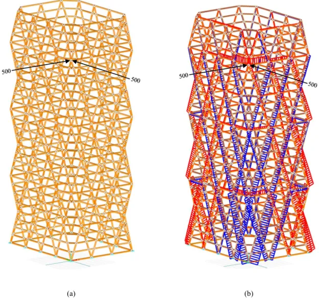
It should be noted that another important characteristic of diagrid structures is the ability to distribute asymmetric loading. Figure 21(a) shows the Hearst Tower diagrid structure without mega columns subjected to an overload of 500 kips applied at the corner of the structure in the X
and Y direction. Figure 21(b) shows the force distribution in the members and how the diagonals aid in distributing the load across the structure making it safer in the event of an asymmetric localized load.
(a) (b)
Chapter 4
Alternate Geometries for Timber LFRS
Using the Hearst Tower as a precedent design and inspiration to develop additional layouts of external elements for timber lateral systems, this chapter focuses on alternate geometries to achieve appropriate strength and lateral stiffness for tall timber buildings. In section 4.1, a minimum compliance continuum topology optimization problem is solved using MATLAB. A rectangular shape representing a building is subjected to wind loading and the resulting shape formulated the concepts for the exterior bracing layouts discussed in section 4.2 and analyzed in the following chapter.
4.1 Topology Optimization
Topology optimization is frequently used to optimize the layout of material for a given design space, loads, and boundary conditions. A problem was formed to simulate a braced frame subject to wind loading with fixed connections at the base of the prismatic element as seen in Figure 22. It assumes similar dimensions to a high-rise building at a smaller scale, and has an increasing triangular distributed load applied to simulate the wind loads. This problem is formulated as a maximum stiffness (or minimum compliance) objective. This is a continuum topology optimization problem using the density-based approach.
The optimization is stated as: minimize 𝑓 = 𝐅𝐓𝐝 𝜌 subject to h = 𝐊(𝜌 )𝐝 − 𝐅 = 0 𝑔 = 𝜌 𝑣 ∈ − 𝑉 ≤ 0 𝜌 ≤ 𝜌 ≤ 1 ∀ 𝑒
Where F is the global load vector, d is the vector of free displacements, e defines each individual element, 𝜌 is the element density, 𝐊(𝜌 ) is the global stiffness matrix, 𝑣 is the element volume, and V is the total allowable material volume. The objective is to maximize the stiffness of the structure, which is the same as the goal to minimize the compliance. The various moduli of elasticity (E1=2100 ksi, E2=1700 ksi, E3=1785 ksi) for the timber are found in the material database from RFEM.
The topology optimization was performed using the fmincon function in MATLAB in conjunction with an FEM solver for 2D elements (Carstensen, 2017). Within this MATLAB code, properties of a material are defined in the material matrix, D. For plane stress, Hooke’s law states
σ = 𝐃ε For an isotropic material, this is defined as
𝜎 𝜎 𝜏 = 𝐸 1 − 𝜈 1 𝜈 0 𝜈 1 0 0 0 1 − 𝜈 2 𝜖 𝜖 𝛾
For an orthotropic material, this is defined as
𝜎 𝜎 𝜏 = ⎣ ⎢ ⎢ ⎢ ⎡ 𝐸 1 − 𝑣 𝑣 𝐸 𝑣 1 − 𝑣 𝑣 0 𝐸 𝑣 1 − 𝑣 𝑣 𝐸 1 − 𝑣 𝑣 0 0 0 𝐺 ⎦ ⎥ ⎥ ⎥ ⎤ 𝜖 𝜖 𝛾
within a given design space. A sensitivity analysis is then performed during each iteration to evaluate the impact that the variation of material densities has on the objective function. The sensitivity is the derivative of the objective function with respect to the material densities. (SIMP, 2019). For this problem a SIMP interpolation model was used:
𝐊 = ((𝜌 ) + 𝜌 )𝐊𝟎= 𝜌 𝐊𝟎
And the sensitives were multiplied:
𝜕𝑓 𝜕𝜌 = 𝜕𝑓 𝜕𝜌 𝜕𝜌 𝜕𝜌
The problem was set up to pursue a 0-1 design which decides if material should be placed (1) or not placed (0). A filter was created with a variable radius value to avoid the checkerboarding effect that results with the SIMP interpolation model. This introduced another design variable, 𝜙 which is related to the respective element density through 𝜌𝒆, where:
𝜌𝒆= 𝜇 = ∑ 𝑤(𝑥 − 𝑥̅ ) ∙ 𝜙
∑ 𝑤(𝑥 − 𝑥̅ )
The neighborhood of element e contains the design variable 𝑖 if the location 𝑥 is less than a distance of 𝑟 away from 𝑥̅ , the element centroid:
𝑖 𝜖 𝑁 if ‖𝑥 − 𝑥̅ ‖ ≤ 𝑟 The weight function is given by:
𝑤(𝑥 − 𝑥̅ ) =
𝑟 − ‖𝑥 − 𝑥̅ ‖
𝑟 if 𝑖 𝜖 𝑁
0 𝑜𝑡ℎ𝑒𝑟𝑤𝑖𝑠𝑒
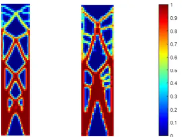
This method was carried out for an isotropic material (steel) and for an orthotropic material (timber). The resulting material distribution for the element shown in Figure 22 is consistent with material characteristics of steel and timber, as is evident in Figure 23.
Figure 23. Optimized Solutions for the Steel (left) and Timber (right) Design Problem
It can be seen that introducing the nonlinearity creates mesh dependency. For the iterations using steel, the material is placed symmetrically with respect to the vertical and horizontal axes which is expected for an isotropic material. For the timber, more material is placed vertically, or along the strong axis which is typically along the grain of the wood. The optimized solution for the timber design problem demonstrates a layout similar to a steel braced frame but with larger modules created from solids and voids that look like mega bracing. It demonstrated a high-waisted brace topology similar to that discovered by Stromberg and Beghini (2012). This research uses topology optimization to design steel braced frames and arrived at a result with the crossing of the braces at the ¾ point along the height of the bracing module, creating the so called “high-waisted” brace. Using these results, various mega bracing topologies were created to analyze the stiffness of a timber lateral system based on this layout.
4.2 The Timber Mega Brace
Figure 24 shows a 2D view from RFEM of the layout of the bracing using the high-waisted brace topology as previously discussed. Because of the advantages of having multiple bays, an additional layout was created having two bays of the high-waisted brace. These layouts still maintain the geometry of four floors per module, and the chamfered corners similar to the Hearst Tower. However, the Hearst Tower only had the diagonals on the exterior and this model integrated the perimeter columns resulting in a braced frame system. Additionally, the Hearst Tower has a footprint of 120 x 160 feet and overall height of 597 feet.
(a) (b)
Figure 24. Two Braced Frame Topologies Using the High Waisted Brace Concept
The above models have an adjusted footprint of 140 x 140 feet for symmetry and overall height of 392 feet. The timber used is again 30F-2.1E Southern Pine and example floor plans for two different levels of Figure 24(a) are shown in Figure 25(a) and (b). The same gravity and lateral loading assumptions apply to this model as the previously discussed timber Hearst Tower feasibility study, except 100% of the wind loading is applied to the structure instead of 25%. A line representing the increasing magnitude of the distributed wind load is shown in Figure 26. The arrows represent uniform loads in kip/feet applied along the length of the exterior beams at each level based on the tributary floor height; the detailed wind loading calculations can be found in Appendix A. The sizing and optimization of variations of the layouts from Figure 24 are discussed in Chapter 5.
(a) (b) (c) Figure 25. Building Geometry for Braced Frame Topologies shown in Figure 24 (a) Typical Floor Plan at Section 1
(b) Typical Floor Plan at Section 2 (c) Overall Dimensions
Chapter 5
Hybrid Systems
This chapter begins with an overview of steel hybrid systems. Various timber and timber-steel hybrid layouts inspired by Figure 24(a) and 24(b) were created and modeled in three dimensions in RFEM and analyzed under appropriate loading conditions. Critical comparative analyses were performed for the layouts and the stiffness was compared to the embodied carbon and total weight of the structures. A representative member was analyzed and a hand calculation was performed to verify the optimization performed by RFEM. Lastly, diagrid nodes are discussed and recommendations are made for timber-steel diagrid nodes.
The layouts from Figure 24 can be broken down even further to evaluate where steel elements can be used in place of timber bracing in order to improve structural performance. Several studies have been done on the combination of steel and timber, especially to reach taller heights. An experimental study by Loss and Frangi (2017) investigates the in-plane stiffness of steel-timber hybrid floor diaphragms. This study finds that floor diaphragms with CLT panels and steel columns represent an attractive alternative to common timber solutions for earthquake resistant residential buildings because of the favorable material properties of steel when used for connections. Another related hybrid example is the Training Academy Mont-Cenis in Herne, Germany which is a long span structure made of several hybrid trusses. It is a prominent feature that successfully demonstrates the interaction of different materials that are selected and placed according to their specific properties (Keil, 2000).
Most buildings with CLT walls and/or floors use steel connections to achieve desired performance, so it is natural to study where else is an ideal placement for steel. The benefits of using these hybrid systems is for the material to be placed where it performs best or for loading conditions in which it can compensate for the weakness of another material. If this were a true optimization in pursuit of the stiffest lateral system, the result would prove to be all steel. However, a parallel objective for the present study is to reduce the embodied carbon of our buildings and therefore the various layouts will be analyzed and compared by their structural performance and carbon impact.
5.1 RFEM Model Definition
The various layouts seen in Figures 27 and 39 were produced in order to optimize placement for timber and steel elements. Some columns were shifted to avoid potential congestion of elements and complex joints. These models have 28 stories with a height of 14 feet per story. Unlike the Hearst Tower, the diagrid extends all the way to the base of the structure rather than being raised on large mega-columns. The model assumptions discussed in section 3.2.1 apply to this model and the loading was applied in a similar fashion. The gravity loading remains the same and the specific wind loading calculations for the new height for these layouts can be found in Appendix A. Rigid surfaces were used at each floor to generate rigid connections between adjacent objects and simulate the behavior of a diaphragm. All hinge conditions were deactivated on the diagonal members creating rigid connections that transfer moments.
The members of the layouts from Figures 27 and 39 were divided into 7 modules separated at every fourth floor which can be seen in Tables 4 and 5. Each diagonal member was divided at every intersection and rigidly connected. Each module from Figure 27(a) has 312 members and each module from Figure 39(a) has 360 members. The add-on modules RF-TIMBER AWC and RF-STEEL AISC were used to optimize the members of each module allowing for the smallest member sizes to be chosen without exceeding the strength and serviceability limits. RF-TIMBER designs according to NDS-2018, ASCE 7-16, and 2018 IBC. The cross-section resistance design analyzes tension and compression along the grain, bending, and shear strength with and without torsion. The Equivalent Member Method is used to design structural components to check buckling and lateral-torsional buckling and the relevant cross-sections are modified in the optimization process. RF-STEEL performs cross-section optimization for a wide range of cross sections using ASCE 7-16. Certain parameters can be specified such as lateral supports, effective lengths, the lateral-torsional buckling modification factor, or the shear lag factor. The results from the optimizations of each add-on module shows the design ratio and corresponding cross section.
5.2 One Bay Hybrid Layout
The layouts seen in Figure 27 retain the outer shape of the Hearst Tower as seen in Figure 25(c) but have various material assignments for the exterior elements. The timber used for this analysis
is 30F-2.1E SP Softwood, and the steel is ASTM A992 Grade 50. Each structure was modeled and analyzed in 3 dimensions in RFEM to measure the lateral stability and corresponding embodied carbon.
(a) (b) (c) (d)
Figure 27. Various Layouts for One Bay of the High Waisted Brace (Gray=Steel, Orange=Timber)
For each of the layouts in Figure 27, the members of each module were optimized using Load and Resistance Factor Design (LRFD), their sizes adjusted accordingly, and the entire structure was again analyzed under the appropriate loading. For this study it is assumed that the members will be encapsulated, so the size of the cross sections were not increased to account for the layer of char that forms on the outside of timber members. If the designer chooses to expose the timber members, about 3 inches will have to be added to each side of the cross section for a two-hour fire rating to be achieved, and the timber weight and embodied carbon values will subsequently increase. Additionally, the sizes of each cross-section can manually be adjusted for constructability reasons. The member dimensions listed as width x height have the height parallel to the façade in the vertical direction, making the second dimension listed responsible for resisting bending. Table 4 shows the size of the optimized members from each module, total weight of each material, total deflection, and the embodied carbon of the structure.
Figure 28. Deflected Shape of One Bay Layout
Table 4. Results of the One Bay Hybrid Layouts (Gray=Steel, Orange=Timber)
Module 7 6 5 4 3 2 1 (7) Timber, Steel 10x9 9x8 W12x53 11x9 W6x15 8x9 W12x65 (6) Timber, Steel 11x11 10x11 W14x132 13x10 W8x28 10x10 W14x145 (5) Timber, Steel 14x12 12x14 W14x145 15x12 W8x31 11x14 W14x176 (4) Timber, Steel 15x13 15x13 W14x233 13x17 W10x45 12x15 W14x257 (3) Timber, Steel 14x18 16x16 W14x283 16x18 W10x45 13x19 W14x283 (2) Timber, Steel 19x16 17x18 W14x342 14x24 W10x60 15x19 W14x398 (1) Timber, Steel 17x19 17x18 W14x550 18x20 W12x72 16x16 W14x455 Timber Weight (k) 1829 1395.3 1717.9 1023.2 Steel Weight (k) - 1838.1 224.3 3228.8 Deflection (in) 6.337 3.404 5.994 1.923 CO2 Emissions (kg) 721,773 2,906,446 1,701,082 3,863,192
Figure 29. Embodied Carbon of Structures from Figure 27
Figure 30. Stiffness of Structures from Figure 27 0 50 100 150 200 250 300 350 400 450 All Timber
Figure 27(a) Figure 27(b)Steel Inside Steel OutsideFigure 27(c) Figure 27(d)All Steel
CO 2 (k g) x 10 00 0
Embodied Carbon
Steel Timber 0 1 2 3 4 5 6 7 All Steel Figure 27(d) Steel Outside Figure 27(c) Steel Inside Figure 27(b) All Timber Figure 27(a)Lateral Deflection (inches)
Figure 31. Stiffness vs. Total Weight of Structures from Figure 27
Figure 32. Stiffness vs. Embodied Carbon of Structures from Figure 27
All Timber Figure 27(a) Steel Inside Figure 27(b) Steel Outside Figure 27(c) All Steel Figure 27(d) 0 1 2 3 4 5 6 7 0 500 1000 1500 2000 2500 3000 3500 4000 4500 D ef le ct io n (in ch es )
Total Structure Weight (kips)
Stiffness vs. Total Weight
All Timber Figure 27(a) Steel Inside Figure 27(b) Steel Outside Figure 27(c) All Steel Figure 27(d) 0 1 2 3 4 5 6 7 0.0 50.0 100.0 150.0 200.0 250.0 300.0 350.0 400.0 450.0 La te ra l D ef le ct io n (in ch es ) CO2 (kg) x 10000
The overall deflection of the various structures from Table 4 are much less than their limit of h/500, or 9.408 inches. This is due to the optimization process used in RFEM which optimizes the members of each module. The results showed that the ultimate strength limit state controlled rather than the serviceability limit state. As previously stated, the sizes of the members can be adjusted for a smooth transition between modules, or for other cost and constructability reasons.
Figure 29 shows the embodied carbon of each structure and the contribution made from either timber or steel. Figure 27(a) has the lowest embodied carbon, and Figure 27(d) has the highest value with most of the contribution from steel. Figure 30 displays a comparison of the overall deflection of the structures with the all-timber structure having the largest value. Figures 31 and 32 display the stiffness versus total weight and stiffness versus embodied carbon of the
structures, respectively. These figures can help designers make informed decisions for placement of different materials in exterior lateral systems.