HAL Id: hal-01455325
https://hal.univ-grenoble-alpes.fr/hal-01455325
Submitted on 3 Feb 2017
HAL is a multi-disciplinary open access
archive for the deposit and dissemination of sci-entific research documents, whether they are pub-lished or not. The documents may come from teaching and research institutions in France or abroad, or from public or private research centers.
L’archive ouverte pluridisciplinaire HAL, est destinée au dépôt et à la diffusion de documents scientifiques de niveau recherche, publiés ou non, émanant des établissements d’enseignement et de recherche français ou étrangers, des laboratoires publics ou privés.
Mechanical-Based Kalman Filter and Curvilinear ROI
Prediction
Paul Mignon, Philippe Poignet, Jocelyne Troccaz
To cite this version:
Paul Mignon, Philippe Poignet, Jocelyne Troccaz. Beveled-Tip Needle-Steering Using 3D Ul-trasound, Mechanical-Based Kalman Filter and Curvilinear ROI Prediction. ICCARV: Interna-tional Conference on Control, Automation, Robotics and Vision, Nov 2016, Phuket, Thailand. �10.1109/ICARCV.2016.7838840�. �hal-01455325�
Beveled-Tip Needle-Steering Using 3D Ultrasound,
Mechanical-Based Kalman Filter and Curvilinear ROI
Prediction
Paul Mignon
Grenoble Alpes University, CNRS, TIMC-IMAG, 38000
Grenoble, France paul.mignon@imag.fr
Philippe Poignet Montpellier University, LIRMM,
161 rue Ada, 34095 Montpellier, France philippe.poignet@lirmm.fr
Jocelyne Troccaz Grenoble Alpes University, CNRS,
TIMC-IMAG, 38000 Grenoble, France jocelyne.troccaz@imag.fr
Abstract—This paper introduces a new robust 3D ultrasound needle detection approach integrated in a 3D needle steering system associated to a real-time path planning. The robustness of an existing algorithm is improved by limiting the needle detection to a curvilinear region of interest (ROI) using a novel mechanical-based prediction model. This linear model is also used in a Kalman filter to reduce detection noise and reject false detections. These two improvements drastically increase quality of our feedback. Finally, the 3D needle steering system is able to reach a target in phantoms with a maximal error of 0.8 mm without obstacle and 1.6 mm with obstacle.
Keywords - Needle steering; needle detection; ultrasound; Kalman filter
I. INTRODUCTION
To reduce patient injuries and guarantee procedure success, needle-involved clinical procedures require very fine precision during insertion. This problem has motivated many research for robotizing needle insertion. Among them, needle steering - i.e. fine control of needle curvature for the execution of curved trajectories toward a target - has received increasing interest over the last decade.
A. Needle Steering and Path Planning
Needle steering can be performed using active or passive needles. Active needles have the ability to act on their own deformation while passive needles use external forces.
Passive needle steering can be performed by applying forces and torques on needle base or by using beveled-needle tip asymmetry to bend the beveled-needle in tissues.
In [1], DiMaio introduces a 2D finite element model of tissue and needle deformations to guide a needle tip by acting on its base. A path planner based on potential fields enables reaching a specific point. Glozman [2] reduces the computation time by using a needle/tissue deformation model based on beam theory and virtual springs instead of finite element.
The needle base manipulation method has still an important drawback: needle base movement influence on needle tip tends to decrease when the needle is deeply inserted. Thus, forces applied to the needle base need to be
increased with insertion depth and could generate traumas on the patient.
The second method does not suffer from this drawback and uses the deformation due to the force applied by the tissue on the beveled needle tip.
Several designs have been proposed to improve bevel-tip needle deformation or reduce patient injuries; a review of these designs can be found in [3].
A model of needle deformation is still necessary to plan needle insertion path. Webster, in 2006 [4], developed a simplified kinematic model which approximates needle trajectory by a circular path. The arc radius depends on tissue and needle mechanical properties. Duty-cycling (DC) methods, introduced in [5], allow to modify this radius by alternating pure insertion and insertion with rotation.
Some planning algorithms based on Markov Decision Process [6] or Rapidly-exploring Random Tree (RRT) [7] use the previous kinematic model in 2D. Later, geometric inverse kinematic [8], stochastic model [9] or RRT [10] have also been used for 3D planning. Patil in [10] used the 3D RRT rapid-replanning strategy from [7] to steer a needle while avoiding obstacle and perturbations. This fast position feedback allows to achieve closed-loop insertion and reduce errors in control and planning. For this reason, we use the same approach to guide a needle in 3D.
B. Needle Detection
Fluoroscopy [11] or MRI [12] are commonly used to detect needles. However, Ultrasound (US) stays the safer, less expensive and more practical imaging modality for intraoperative purpose.
In [13], Abayazid uses US imaging based on a 2D probe mounted on a motorized support to detect and steer a needle tip using the 3D RRT replanning approach. This “frame by frame” tracking method makes detection more robust but needs the needle to be roughly normal to the US plane.
In [14], Adebar extends this “frame by frame” segmentation approach to a 3D motorized probe. Color-Doppler mode is associated with an ultrasound buzzer at the needle base, to improve needle detection. An Unscented Kalman Filter (UKF) filters the detection using the
non-linear unicycle model to predict needle tip displacement between two images.
We previously developed a detection method based on color-Doppler and needle rotation during insertion [15]. The detection is based on 3D reconstructed volume from a commercialized endorectal 3D probe. Unlike [13] and [14], the needle orientation in relation to the probe is therefore not constrained by the detection algorithm.
We chose to use a Random Sample Consensus (RANSAC) algorithm inspired by [16]. This algorithm can be successfully used to extract polynomial (Bezier) curves approximating the needle shape from noisy environment.
In [17], Chatelain uses this reconstructed 3D approach and a Kalman Filter (KF) to improve needle detection given by a similar polynomial curve RANSAC. This KF uses the position continuity of each control point as the model for the needle displacement. However, as the needle is manually inserted, no prior information could be added to the filter.
Later, the limitation of the detection to a cylindrical ROI make it more robust [18].
C. Contributions
In this paper, we present a novel needle tracking approach based on a KF combined with a novel 3D mechanical model inspired by [19]. Along with mechanical properties, this model also integrates robot information such as insertion speed and orientation of the needle to have a better estimate of the whole 3D shape deformation of a Bezier curve approximating the needle.
This mechanical model also increases the precision and robustness of our detection giving a predicted curvilinear ROI using the last needle detected in the 3D US image (see III.B).
This new approach is compared to the similar kinematic approach proposed in [17] by tracking a needle on 3D image sequences.
Finally, a 3D needle steering system merges these contributions using an existing brachytherapy robot prototype [20] and a RRT replanning algorithm [7]. Steering results obtained on phantoms with and without obstacle are summarized in section IV.C.
II. MECHANICAL-BASED KALMAN FILTER
A. Kalman Filter process
Standard needle tracking methods based on noisy images processing may lead to false detections. For that reason, we use a KF to filter the result.
The discrete KF is based on the knowledge of variables (state) evolution. This evolution is translated into a linear equation. The KF assumes that a process noise and a measurement noise, both Gaussian, corrupt respectively the prediction model and the measurement. Filtered state is computed by an optimization between the prediction and the measure. For more information about KF, see [21].
The models described in Section II.B and II.C will be used as prediction, separately. In the mechanical KF the state represents the Bezier curve control point coordinates
⋮ with . The measurement noise, about
1 mm, corresponds to the standard deviation of each control point estimated from 100 segmentations. The process noise, around 0.1 mm, is computed from comparisons between simulations and real needle insertions.
The filtered needle segmentation corresponds to the updated estimate of the control points. The ROI is created with a prediction computed from the models (see III.B). In addition, we use a “validation gate” to reject high false detections (see [21] for more details).
B. Mechanical-based Model
As mentioned in Section I.A, some needle deformation models use virtual springs to simulate needle-tissue interactions. For instance, in [19], one of these models was developed to estimate needle deformation caused by needle asymmetry. This model considers needle as a piece-wise polynomial curve in 2D. Polynomial coefficients are computed by minimizing the energy accumulated in the system and the work produced by the beveled needle tip force.
We use a similar model and apply it on a 3D Bezier curve resulting from the detection step introduced in Section I.B. The deformation is limited by the polynomial aspect of the Bezier curve. However, simulations show that cubic or quadratic Bezier curves are sufficient to describe slight needle deformations.
Being given a needle at a time t described by a Bezier curve and its control points , every curve points could be expressed by the relation (1):
1 ⋯ ( 1 )
where the matrix depends on the order of the Bezier curve N and s is a parameter between 0 and 1. Characters in bold represent vectors and matrices.
Once the needle appears in the image, its visible base (i.e. the needle point in the image nearest to the needle base) is assumed to be fixed. It means that the first control point does not move. The visible tip moves in the direction tangent to the needle tip. Tip and base speeds are supposed to be equal. Thus we suppose there is no axial compression in the needle.
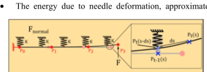
The energy of the system could be divided into the three following components:
• The energy due to needle deformation, approximated
Figure 1. Two successive steps of the mechanical-based needle model are visualized. ds represents the needle displacement due to insertion speed.
for small deformation by (2) :
. ( 2 )
where E is the Young's modulus of the needle, I is the second moment of area computed from needle section, L is the needle length approximation and represents the second derivative of in relation to s.
• The energy accumulated in the virtual springs which simulates the needle-tissue interaction. It could also be approximated for small needle deformations by (3):
‖ ‖ ( 3 )
where K is the virtual spring stiffness per length, t represents the current instant and t-1 the previous instant. is the distance traveled by the point during the insertion step
and is expressed by where is the insertion
speed and dt is the period between two steps. Including that term allows to consider the needle insertion movement directly in the virtual spring energy.
• The work of the force F acting on needle tip:
∙ 1 1 ( 4 )
The direction of the vector F is determined by last needle direction and needle roll angle given by the robot. Thus, we neglect torsion and suppose that needle base and tip roll angles are the same.
The approach consists in computing optimal control point coordinates which minimize those energies. To that purpose, we compute the system of differential equations (5).
, , , , 0
⋮
( 5 ) Differential equations (5) lead to a linear system of 3xN depending on current ( ) and previous ( ) control point coordinates.
It results in a matrix relation between current and previous control points and the force applied on the needle tip. This expression defined in (6).
( 6 ) where and depends on E, I , , δs, L K and the order of the Bezier curve. depends only on F. Using inverse or pseudo-inverse, the current control points coordinates are obtain directly from the previous ones.
The cutting force F is defined in the literature as one of the three forces applied to the needle during insertion in the tissues [22] and is supposed constant at each step. F is modulated according to needle insertion DC (value between
0 and 1 corresponding to rotation time over insertion time)
by the following relation 1 .
corresponds to the true force applied on needle tip.
The virtual spring stiffness K reflects needle-tissue interaction. It therefore depends on the tissue and needle mechanical properties.
Since this model is linear, there is no need for a UKF as used in [14]. This model also computes the entire needle shape deformation, not only needle tip displacement, and is therefore more precise for ROI selection (see III.B).
C. Kinematic model
In order to show the added value of the presented approach and because of the similarity in the detection processes, we compare our KF to a more standard model [17]. This model is based on the control point kinematic relation between point position and speed. To have a more relevant comparison, we will add to this model information from the robot using needle tip velocity. A virtual measure of velocity vector is created from the last needle direction detected and the insertion speed given by the robot.
III. NEEDLE STEERING APPROACH
A. Control Scheme
The strategy used to steer the needle consists in two stages: the low-level control loop and high-level control loop (see Figure 2). The former concerns the robot. The latter is composed of the US acquisition, needle segmentation, the novel KF and the path planning. The path planning returns a path composed of circular arcs and is transformed into control inputs by the DC algorithm.
The insertion and rotation speeds are defined by the user. Thus, the DC algorithm takes as input the DC value and the total insertion distance. It returns several insertion steps controlling the insertion distance and rotation angle for each step. To avoid involuntary change of orientation, the rotation angle must be a multiple of 360°. Thus the rotating time has a lowest value which also limits the total insertion time step. To avoid the influence of starting and stopping motor transient phases, we also keep rotating time superior to 500 ms.
B. Selection of the Region of Interest
The mechanical or the kinematic model are used
separately as prediction for ROI selection in the next segmentation. Based on the acquisition time (supposed constant), the model returns a Bezier curve corresponding to the predicted needle position in the next image.
A specific thickness (called side margin), corresponding to apparent needle diameter, is added to the ROI (see Figure 4). A margin at needle tip could also be set by the user in some cases, for example when the model used to predict needle displacement does not integrate needle progression.
ROI based detection using RANSAC and KF has already been investigated [18] but only with a cylindrical ROI which does not evaluate needle deformations: the prediction model uses tip velocity measurement relying on speckle tracking. Here, we use robot information as well as mechanical-model and avoid potential errors from speckle tracking velocity detection.
C. Experimental Setup
PROSPER is a robot developed for brachytherapy procedures [20]. It has a positioning module with five motors to pre-position and orient the needle tip outside the patient and an insertion/rotation module with two motors for needle steering inside tissues.
An Ultrasonix RP acquires 3D images from an endorectal US probe and sends it to a computer. A GPU-based 3D reconstruction algorithm inspired by [23], using 2D Cartesian slices instead of RF signal, compensates for transducer constant velocity in acquisition. The framerate depends mainly on the 3D probe swept angle, we therefore
limit it to 30°. The final 3D resolution is 0.27x0.27x1.37 mm farthest from the probe (50 mm) and the framerate is around 1 volume per second.
The user selects target position in a pre-insertion US image and can also locate obstacles corresponding to critical areas. The needle is inserted enough to make it visible in the image and is first located by the user. Then our automatic segmentation process is used to track the needle and planning is performed by RRT. These steps are repeated for each incoming image and allows to compensate for segmentation, path planning or control errors and possible robot compliance.
In order to have reusable phantoms for needle steering experiments, we selected two types of phantoms: a paraffin gel associated with a Vybar polymer (massic proportion of 25%) and PVC based phantoms. The paraffin phantoms are preferred because of the low manufacturing complexity. Moreover, the polymer assures the control on the phantom stiffness and simply heating it allows to recover its initial shape and stiffness.
IV. RESULTS
A. Model Parameters Definitions
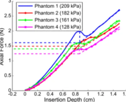
In order to have an estimate of the cutting force in our future experiments, four different needles (2 biopsy needles, 1 brachytherapy needle and 1 Nitinol needle) have been mounted separately on a RAVEN II robot equipped with a force sensor. This sensor measures the force applied on the needle base during its insertion into PVC phantoms. Each phantom has a different apparent Young's modulus, previously measured by LASTIC [24]. The norm of is extracted from a graph of the total axial force against the insertion depth.
Figure 3 represents the axial force detected on the standard brachytherapy needle (stainless steel, 17 gauges) base during the insertion in four phantoms with different elasticity. The first peak corresponds to the puncture force necessary to penetrate in the tissue. The slope after the peak corresponds to the regular friction force increase, proportional to the insertion depth. could be computed from the friction force slope and the puncture point. The same process is applied to every needle. Results are given in Table 1.
Figure 5. Needle steering experimental setup. The 3D probe stay fixed during insertion and the robot is designed for brachytherapy purpose.
Figure 4. ROI selection schematic: the pixels are swept along the predicted curve with a side margin of 2 pixel and a tip margin of 21pixels.
Figure 3. Total axial force in relation with insertion depth for a standard brachytherapy needle in four phantoms with different elasticities.
The virtual spring stiffness is then estimated from a comparison between needle insertion simulations and experimental results. The four needles have been inserted in the different phantoms and the stiffness corresponding to the best fit is returned. The cutting force and spring stiffness are summarized in the Table 1.
Table 1. Summary of the estimated cutting force F and the deduced stiffness of the virtual springs K used in the mechanical-based model
Needle Brachy. Biopsy 1 Biopsy 2 Nitinol
Diameter (mm) 1.15 0.723 0.644 0.511 Bevel Angle (°) 36 30 30 24 Young’s Modulus (kPa) 30 K (N/mm) F(N) 0.17 0.06 0.04 0.05 300 120 80 50 128 K (N/mm) F(N) 2.11 0.78 0.71 0.30 2400 1100 800 180 161 K (N/mm) F(N) 2.38 0.81 0.71 0.34 2400 1000 800 230 182 F(N) 2.53 1.08 0.89 0.44 K (N/mm) 2600 1400 1000 320 209 F(N) 2.74 1.40 1.13 0.49 K (N/mm) 3000 1800 1600 400
B. Needle Tracking Using Kalman Filter and ROI
The noise in our detection comes mainly from RANSAC non-determinism and from US intrinsic noise in the image. Table 2 summarizes errors for static needle detections in 26 acquisitions in 3D. It presents shape error (mean along the needle shape), needle tip position and direction errors. Even if the standard deviation error is already very low without KF, we can see that KFs reduce the standard deviation of the errors and thus increase the precision of the detection. However, the KFs do not reduce mean errors. Thus they do not affect detection accuracy during static detections.
Table 2 Errors (mean ± standard deviation) for a static needle detection
No KF Kinematic Mechanical
Shape error 1.13 ± 0.13 mm 1.14 ± 0.05 mm 1.13 ± 0.07 mm
Tip error 1.07 ± 0.33 mm 0.91 ± 0.12 mm 1.06 ± 0.15 mm
Direct. error 6.26 ± 0.76 ° 3.68 ± 0.52 ° 5.79 ± 0.37 ° The purpose of the following experiment is to compare tracking performance in three cases and to determine which model is the most appropriate.
In the first case, no model is applied, the ROI is then determined from last needle detection. The second case involves the kinematic model and the last case uses the mechanical model. Results have been compared to manual segmentations. A 0.5 mm nitinol needle is pre-curved at 3
mm from its tip to increase bending in the paraffin phantom. The needle is inserted at 1 mm/s. F and K for a paraffin gel phantom (80 kPa) were returned from simulations and are 1 N and 320 N/mm respectively. Side margin is set to 3.2 mm corresponding to the apparent needle thickness in the acquired volume. When no model is used, a 1 mm tip margin is added to manage needle progression. For the two cases using model, no tip margin has been added, the margin is therefore the result of the prediction.
In practice, the very low framerate (1Hz) of 3D acquisition increases the model impact for ROI selection. To emphasize further the difference between models, the needle performs a double-bend path.
Figure 6 shows tracking results of a double-bend path and the profile of the insertion speed.
The tracking without prediction model loses the tip when the needle stops for orientation change. It is caused by the presence of a constant tip margin and the hyper-echogenicity of the phantom.
The kinematic model keeps tracking the needle tip during stopping time thanks to the insertion speed given as input. However, it loses the needle tip when the insertion restarts due to the change in needle orientation.
The mechanical model allows to adapt tracking to the change in orientation by using needle tip force vector as input. It allows the needle to be tracked for the rest of the insertion.
Figure 7. 3D needle steering projection on XZ and XY plans: with (b) and without (a) obstacle. Background shows the needle in 3D ultrasound slices. Figure 6. Errors on needle tip pose during three different tracking and insertion speed profile. The 180° bar corresponds to the change in direction of the double bend path.
C. Needle Steering Experiments
This illustrates the efficiency of the new 3D US tracking. This section presents the 3D needle guidance toward a virtual target. For this purpose, we integrate all steps mentioned in section III.A: tracking with mechanical KF, rapid 3D RRT re-planning and DC control. Experiments are performed in two different phantoms with different elasticities (180 kPa and 80 kPa). For each phantom, needle steering is achieved with and without obstacle avoidance (see Figure 7). We use the 0.5 mm pre-curved nitinol needle and an insertion velocity of 0.5 mm/s. The error is the distance between the virtual target and the final needle tip position obtained by the automatic segmentation.
Errors found without obstacle are 0.5 and 0.8 mm. With one obstacle, errors were 1.6 and 0.7 mm. However, let us remind that the detection accuracy is around 1 mm. The working space is limited by the needle maximum curvature, which could cause some targets to be unreachable and increase final error. In this experiment only reachable targets were selected.
V. CONCLUSION
This paper presents 3D needle detection and steering using a novel mechanical-based ROI selection and KF. This approach will be tested in a very short term on more complex tissues such as heterogeneous phantoms or biological tissues. Future work also includes target and obstacles automatic tracking in order to compensate for tissue deformation.
However; preliminary results are already very encouraging: the mechanical-based model enables to predict needle change in orientation. In that way, the needle is easily tracked even when the tip performs large bending. Thus, this approach offers a more robust feedback for 3D needle steering.
VI. ACKNOWLEDGMENT
This work was partly supported by the French ANR within the Investissements d'Avenir program (Labex CAMI) under reference ANR-11-LABX-0004. We also want to thank Ederson Dorileo and Abdulrahman Albakri for their help.
VII. REFERENCES
[1] S. P. DiMaio and S. E. Salcudean, “Needle Steering and Model-Based Trajectory Planning,” in MICCAI, 2003, vol. 2878, pp. 33– 40.
[2] D. Glozman and M. Shoham, “Flexible Needle Steering and Optimal Trajectory Planning for Percutaneous Therapies,” in
MICCAI, 2004, vol. 3217, pp. 137–144.
[3] N. J. Van De Berg, D. J. Van Gerwen, J. Dankelman, and J. J. Van Den Dobbelsteen, “Design Choices in Needle Steering — A Review,” vol. 20, no. 5, pp. 2172–2183, 2015.
[4] R. J. Webster, J. S. Kim, N. J. Cowan, G. S. Chirikjian, and A. M. Okamura, “Nonholonomic modeling of needle steering,” Int.
J. Rob. Res., vol. 25, no. 5–6, pp. 509–525, 2006.
[5] J. A. Engh, G. Podnar, S. Y. Khoo, and C. N. Riviere, “Flexible Needle Steering System for Percutaneous Access to Deep Zones
of the Brain,” in IEEE 32nd Annual Northeast Bioengineering
Conference, 2006, pp. 103–104.
[6] R. Alterovitz, A. Lim, K. Goldberg, G. S. Chirikjian, and A. M. Okamura, “Steering flexible needles under Markov motion uncertainty,” in IEEE/RSJ IROS, 2005, pp. 1570–1575.
[7] M. C. Bernardes, B. V Adorno, P. Poignet, N. Zemiti, and G. A. Borges, “Adaptive path planning for steerable needles using duty-cycling,” in IEEE/RSJ IROS, 2011, pp. 2545–2550.
[8] V. Duindam, J. Xu, R. Alterovitz, S. Sastry, and K. Goldberg, “Three-dimensional motion planning algorithms for steerable needles using inverse kinematics,” Int. J. Rob. Res., vol. 29, no. 7, pp. 789–800, 2010.
[9] W. Park, J. S. Kim, Y. Zhou, N. J. Cowan, A. M. Okamura, and G. S. Chirikjian, “Diffusion-based motion planning for a nonholonomic flexible needle model,” in IEEE ICRA, 2005, pp. 4600–4605.
[10] S. Patil, J. Burgner, R. J. Webster, and R. Alterovitz, “Needle Steering in 3-D Via Rapid Replanning,” IEEE Trans. Robot., 2014.
[11] D. Glozman and M. Shoham, “Image-guided robotic flexible needle steering,” Robot. IEEE Trans., vol. 23, no. 3, pp. 459–467, 2007.
[12] N. A. Patel, T. van Katwijk, G. Li, P. Moreira, W. Shang, S. Misra, and G. S. Fischer, “Closed-loop asymmetric-tip needle steering under continuous intraoperative MRI guidance,” in IEEE
EMBC, 2015, pp. 4869–4874.
[13] M. Abayazid, P. Moreira, N. Shahriari, S. Patil, R. Alterovitz, and S. Misra, “Ultrasound-guided three-dimensional needle steering in biological tissue with curved surfaces,” Med. Eng.
Phys., vol. 37, no. 1, pp. 145–150, 2015.
[14] T. K. Adebar and A. M. Okamura, “Recursive estimation of needle pose for control of 3D-ultrasound-guided robotic needle steering,” in IEEE/RSJ IROS, 2014, pp. 4303–4308.
[15] P. Mignon, J. Troccaz, and P. Poignet, “Using Rotation for Steerable Needle Detection in 3D Color-Doppler Ultrasound Images,” in IEEE EMBC, 2015.
[16] M. Uhercik, J. Kybic, H. Liebgott, and C. Cachard, “Model Fitting Using RANSAC for Surgical Tool Localization in 3-D Ultrasound Images,” Biomed. Eng. IEEE Trans., vol. 57, no. 8, pp. 1907–1916, 2010.
[17] A. K. Pierre Chatelain and M. Marchal, “Real-time needle detection and tracking using a visually servoed 3D ultrasound probe,” in IEEE ICRA, 2013.
[18] Y. ZHAO, “Biopsy Needles Localization and Tracking Methods in 3D Medical Ultrasound with ROI-RANSAC-KALMAN,” 2014.
[19] R. J. Roesthuis, Y. R. J. van Veen, A. Jahya, and S. Misra, “Mechanics of needle-tissue interaction,” in IEEE/RSJ IROS, 2011, pp. 2557–2563.
[20] N. Hungr, M. Baumann, J.-A. Long, and J. Troccaz, “A 3-D Ultrasound Robotic Prostate Brachytherapy System With Prostate Motion Tracking,” Robot. IEEE Trans., vol. 28, no. 6, pp. 1382– 1397, 2012.
[21] L. Kleeman, “Understanding and applying Kalman filtering,” in
Proceedings of the Second Workshop on Perceptive Systems, Curtin University of Technology, Perth Western Australia, 1996.
[22] A. M. Okamura, C. Simone, and M. D. O’Leary, “Force modeling for needle insertion into soft tissue,” Biomed. Eng.
IEEE Trans., vol. 51, no. 10, pp. 1707–1716, Oct. 2004.
[23] D. Lee and A. Krupa, “Intensity-based visual servoing for non-rigid motion compensation of soft tissue structures due to physiological motion using 4D ultrasound,” in IEEE/RSJ IROS, 2011, pp. 2831–2836.
[24] P. Schiavone, E. Promayon, and Y. Payan, “LASTIC: A Light Aspiration Device for in vivo Soft TIssue Characterization,”
Biomed. Simul., vol. 5958, pp. 1–10, 2010.