HAL Id: inria-00141624
https://hal.inria.fr/inria-00141624
Submitted on 13 Apr 2007
HAL is a multi-disciplinary open access
archive for the deposit and dissemination of
sci-entific research documents, whether they are
pub-lished or not. The documents may come from
teaching and research institutions in France or
abroad, or from public or private research centers.
L’archive ouverte pluridisciplinaire HAL, est
destinée au dépôt et à la diffusion de documents
scientifiques de niveau recherche, publiés ou non,
émanant des établissements d’enseignement et de
recherche français ou étrangers, des laboratoires
publics ou privés.
Component-based Discrete Event Simulation Using the
Fractal Component Model
Olivier Dalle
To cite this version:
Olivier Dalle. Component-based Discrete Event Simulation Using the Fractal Component Model.
International Conference on AI, Simulation and Planning in High Autonomy Systems (AIS) and
Conceptual Modeling and Simulation (CMS), Feb 2007, Buenos Aires, Argentina, pp.213–218.
�inria-00141624�
inria-00141624, version 1 - 13 Apr 2007
Component-based Discrete Event Simulation Using
the Fractal Component Model
Olivier Dalle M
ASCOTTEproject
I3S-CNRS/I
NRIA/Universit´e de Nice-Sophia Antipolis
B.P. 93, F-06902 Sophia Antipolis Cedex, F
RANCE.
E-mail: [email protected]
Abstract— In this paper we show that Fractal, a generic component model coming from the Component-Based Software Engineering (CBSE) community, meets most of the functional expectations identified so far in the simulation community for component-based modeling and simulation. We also demonstrate that Fractal offers additional features that have not yet been identified in the simulation community despite their potential usefulness. Eventually we describe our ongoing work on such a new simulation architecture built on top of the Fractal model, the Open Simulation Architecture (OSA).
Index Terms— Discrete-event Simulation, Simulation Method-ology, Component-based Modeling, Component-based Software Engineering, Fractal Component model.
I. INTRODUCTION
From an historical perspective, the component-based ap-proach was first popular in the Modeling and Simulation (M&S) community for its descriptive good properties. Indeed, an interesting property of the component-based approach is its ability to model complex systems by dividing the initial system, recursively, into smaller sub-systems. This hierarchical modeling approach was first introduced by Zeigler with the DEVS formalism[1] and later in other formalisms, such as Harel’s State Charts[2]. However, it is worth stressing that a formalism like DEVS is a specification language, that is a non-ambiguous formal language for describing both the behavior and structure of dynamic systems[3]; DEVS is not a program-ming language and does not address the implementation issues of computer simulations1.
In the Software Engineering (SE) community, the component-based approach emerged more recently (in the 90’s) as an evolution of the object-oriented programming (OOP) paradigm. Indeed, the component approach solves one of the major pitfalls of OOP, sometimes referred to as the
hyper-spaghetti objects and subsystems phenomenon[4]. A
side-effect of solving this pitfall is that it enables or makes eas-ier many interesting SE good practices, such as reusing code or making validation and (unit-)testing of code easier. However, it is interesting to note that the descriptive good property of components that was identified in the simulation context was not the main concern addressed by the components in the SE context. Indeed, the first component architectures and models
1As a matter of facts, the implementation concerns of the DEVS formalism
are currently being discussed within the SISO DEVS-SG discussion group (hosted onhttp://www.sisostds.org/).
proposed for SE, such as CORBA[5], COM[6] or JavaBeans[7] do not support hierarchical composition.
In this paper we will show that the Fractal[8] component model is a convenient mean of implementing the component-based approach in discrete-event simulation. In section II, we we first identify the usual M&S activities. Then, in section III, we give a short list of the main motivations and expectations for components in both M&S and SE, before we describe the benefits of the Fractal model in section IV. Finally, in section V we describe how this is applied in the OSA architecture.
II. COMPONENTMODELING& SIMULATION ACTIVITIES
Studying a system using discrete-event computer simula-tions implies several activities. These activities need to be clearly identified in order to establish a classification of the
Roles and Concerns in simulation, two major concepts of
CBSE that will be discussed in the next section. Hereafter, we propose a possible classification of these activities:
• Conceptual model specification: this first modeling step
consists in describing the model the system expert has in mind. Depending on the system expert habits, this description may range from the informal ones (textual, manual drawings) to the more formal ones (based on var-ious formalisms such as DEVS, PetriNets[9], UML[10], SDL[11], Data Flow Diagrams[12],. . . ).
• Software model architecture description: this is the
translation of the conceptual model architecture into a software architecture compliant with the targeted puter simulation software. This description usually com-bines a list of components and a topological descrip-tion of their interacdescrip-tions (bindings). The “shape” of the components depends on the underlying software compo-nent model and may range from the most generic ones like DEVS JavaBeans (eg. SimBeans[13]), or Agents (eg. Swarms[14]) to the most domain-specific ones, such as the Opnet elements (networks, nodes, modules, processes)[15]. The topological description may be either programmed in-line (using binding primitives), or by means of an Architecture Description Language, such as the one found in CD++[16] or OMNet++[17], or both, such as in Fractal.
• Software development: this consists mainly in
imple-menting the behavior of model components using a programming language and developments tools (eg. the
Eclipse IDE[18]), but may also include other develop-ments, such as the sampling policies used to collect the simulation data or the topological description mentioned just above.
• Simulation scenarios configuration: this mainly consists
in setting up the initial parameters of the components in order to reach the initial state of the system (eg. location of vehicles on a map or initial value of a random seed).
• Instrumentation of simulation scenarios: this activity
consists in instrumenting the model with probes that will collect data samples during the simulation run. This may also include more complex tasks, such as defining aggre-gation policies for samples collected by several probes or computing statistical indicators during execution instead of gathering and saving large amounts of data samples.
• Experiment planning: studying a system using computer
simulations often turns into comparing the behavior and performances of the considered system using several vari-ations of a same basic scenario. These varivari-ations consist in using different values for some of the initial parameters in the basic scenario. In order to avoid a combinatorial explosion of the number of parameters combinations, and consequently, of the number of simulation runs, various policies exists[19]. An experiment plan is built by applying such policies.
• Configuration of computational resources: this
activ-ity consists in setting-up deployment parameters for a distributed execution or the scheduling of a batch of simulation runs on a pool of computers.
• Execution control: depending on the mode of execution
selected (animated, debug, batch), several kind of controls may or may not be available to the end user: start, stop, resume execution, step one event, dump the scheduler’s pending event list, and so on.
• Post-processing and analysis: this consists in preparing
the data collected during the simulation runs (merging and formatting the data of several simulation runs) and running computations on these data (eg. statistical com-putations, graph plotting, . . . ).
• Validation and verification: this consists in verifying
that the software model behaves as expected. This may be achieved in several ways, such as using a debugging mode of execution or comparing the data collected during the simulation (or obtained after post-processing) with the data produced by the real system. The latter technique may be automated[20].
III. COMPONENTS:MAIN MOTIVATIONS AND EXPECTATIONS
In [21], Oses, Pidd and Brooks already gave an in-depth analysis of the critical issues in the development of component-based discrete simulation. They conclude that in many cases, technical solutions already exist to address the issues they identified, such as validation and verification, interoperability of existing models, and component or software reuse for example. However, we think that in the latter case, concerning software reuse, the issue is still pending and that
new enabling techniques, such as the separation of concerns, presented in section III-C, should be applied. Prior to this, we first recall in the two following sections the very first motivations of the component-based approach, from a M&S point of view first, and then, from the SE point of view.
A. Reflect Systems structural organization
For M&S, the main motivation for using components is to reflect the structural organization of the System to sim-ulate. For example, in [3], the main motivation presented for the DEVS component model is to provide a formalism for discrete-event modeling that conforms with the Systems Theory principles. In Systems Theory, the observable outputs of a system or sub-system should only result from its external inputs and its internal behavior. Following, in DEVS, compo-nents are used to model such self-contained systems; they are often compared to “black-boxes”, meaning that when standing
out of the box, one is not supposed to access what is inside
the box. Furthermore, in order to better reflect the structural organization of Systems and ease the modeling process, the component models proposed for M&S are usually hierarchical. As already mentioned in our introduction, this is not always the case for the component models proposed for SE.
B. Software reuse
Reuse is certainly the most stated expected benefit of the component-based approach in SE. However, this good property was also clearly identified in the M&S context: as soon as the modeling components result in self-contained entities, one can reasonably expect that these self-contained modeling entities will result in self-contained software components. Unfortunately, as we will show in the next section, these self-contained software components may not be easily reusable, especially when they mix several concerns.
In practice, we may distinguish two levels of component reuse: reuse at source level and reuse at execution level (pre-compiled components and components libraries). The first level offers enough flexibility to allow reusing with modifica-tions of the sources while the second prohibits modificamodifica-tions. And while open source modeling is a common practice, there are situations in which it may not be possible. This is typically the case in a competitive industrial context where disclosing the internals of a proprietary system or technology to concurrent companies may not be acceptable.
It is also worth stressing that in SE, the component models are often linked to an OOP language, which probably explains why the need for hierarchical support at component level is less critical, and therefore less often supported (most OO languages are intrinsically hierarchical).
C. Separation of roles and concerns
The activities identified in section II correspond mainly to the different steps of a computer-based simulation study life-cycle. Notice that the simulationist may iterate several times over each of these steps. In other words, the complete life-cycle may contain several loops. For example, if the
verification and validation step fails, the cycle will loop back to the development step if the failure is due to an implementation error, or to the modeling step, if it is due to a modeling error. Each of these activities has relatively independent objectives and may requires different kinds of knowledge and expertise. When the end-user of the simulation software practises these different activities, we say he plays different roles. In the pro-cess of building a modular simulation software architecture, it looks reasonable to try decompose the simulation architecture in software modules according to these roles. Indeed, because of the relative independence of the activities, the specifications of the services offered to support the user in each role should be able to vary independently over the time in each role.
The separation of concerns concept is somehow similar to the previous separation of roles concept, except that it is not necessarily linked to the classification of the user activities. Indeed, concerns are usually separated into two kinds: func-tional concerns and non-funcfunc-tional concerns2. In the case of a
component-based software, the functional concerns are related to the functional (or business) specification of the component itself (eg. the functional concerns of a cashier component are related to the specification of the cashier); non functional concerns are the remaining concerns that apply to a component but are not specific to that component. Non functional concerns include for example the following ones: life-cycle (start/stop a component), introspection services (self-description of the component), binding (coupling of components), persistence (save/restore the state of a component into a data-base), and so on.
In the case of modeling and simulation, as stated in sec-tion I, the component-based approach may be used both for specifying a model (using a formalism such as DEVS) and for implementing it in a software simulator (using JavaBeans for example). Unfortunately, in many simulators, roles and concerns are not fully separated. For example, in some cases, the code for instrumenting the models may be mixed together with the code of the models. This kind of concern mixing was also observed with the code needed to establish network connections between components in a distributed environment or simply with the code needed to establish bindings (or couplings) between components.
IV. BENEFITS OF THEFRACTAL MODEL
A. Separation of roles and concerns
Fractal provides means of applying the separation of con-cerns and separation of roles in two ways.
First, it provides an Architecture Description Language (ADL) and sophisticated mechanisms for building component architectures, such as factories and template components. Thanks to the ADL, the concern of building the topological description of the hierarchy of components is separated from other concerns. Factories are special components that can dynamically instantiate new components. Therefore, the way components are instantiated may be implemented in a self contained component, which is a mean of separating the
2Functional concerns may also be referred to as business concerns and
non-functional concerns referred to as technical concerns.
instantiation concern from others. As a matter of facts, the default Fractal ADL parser is a factory component. Further-more, the factory component that implements the Fractal ADL parser is a hierarchical component whose content may be partly or totally reused for building new specialized ADL parsers. Template components are special factory components that may be used to build a generic model of (hierarchical) components. Such template models may then be used to instantiate homomorphic copies of the model.
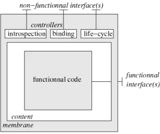
Second, Fractal offers a versatile and extensible framework to support non-functional concerns. This framework consists in embedding each component into a software membrane: the content part of the component implements its functional con-cerns, and the membrane part implements its non-functional concerns. The membrane consists of several controllers, each of which being responsible for a non-functional concern (figure 1). The framework allow the construction of new membranes by assembling new or existing controllers. The selection of which membrane to associate with which content may be specified using the ADL.
Fig. 1. Anatomy of a Fractal component. In this example, the membrane contains three controllers that offers the introspection, binding and life-cycle non-functional services.
B. Shared components
In a hierarchical component model, a shared component is a component that have more than one parent in the component hierarchy. To the author’s knowledge, very few component models do effectively support the shared component fea-ture: the Fractal component model does explicitly support sharing[8] while some others, like JainSLEE[22] provide proxying techniques which is a practical way of implementing sharing.
Regarding DEVS, for example, the formal definition of a Coupled System Specification given by Zeigler et al. in [3] (p. 128), forbids shared components in the general case, because it defines that for a component d ∈ D(N ), where D(N ) is
the set of components referenced by a coupled structure N , the set of influencers Id of the component d is such that Id⊆ D(N ) ∪ {N }. In the case of shared components, the set of
of all the coupled structures that reference d instead of just N :
Id/shared⊆ D(N ) ∪ CS(d) where CS(d) = {n|d ∈ D(n)}.
The DEVS formalism provide a rigorous way of describing systems, hierarchically, with strong mathematical properties, such as closure under coupling. Unfortunately, the fact that this rigorous modeling framework cannot support the concept of shared components does mean that, semantically, shared components are a modeling non-sense.
For example, let’s consider the case of a communication network. the usual way of modeling the architecture of a network of communicating nodes is to follow the OSI flat layered view: a node is made of an application layer, itself connected to session layer, and so on, until the lowest level at which the nodes are physically connected thanks to the network medium.
However, modeling often consists in finding the right trade-off between an exact representation of the system and a reasonable simulation time. In our case study, if the analyst want to study the behavior of an application protocol over a long period, it is certainly not reasonable to model all the layers of the OSI protocol but only focus on the higher ones, which may lead to the model depicted on figure 2 where the
transport networkcomponent is used to model a virtual
link that operates at the transport level between the two nodes.
Fig. 2. Hierarchical decomposition of a two nodes network: a partial OSI layered decomposition.
Unfortunately, despite its conceptual correctness, the hierar-chical model depicted on figure 2 is not easily reusable. First, notice that there is a dependency between thenodecomposite component and the transport networkcomponent: the primer cannot be reused without the later. Second, and far more annoying, is the fact that these component may not easily be plugged in a more complex architecture. Assume for example that we want to model a road traffic network in which some of the vehicles, not all, are equipped with the nodes of the previous example. Assume also that we want to reuse the already exiting hierarchical model of the vehicle depicted on figure 3.
Given the model of the vehicle depicted on figure 3, the correct place where to plug the node component should be somewhere in the electronicscomponent of the vehicle, as illustrated on figure 4.
Fig. 3. Hierarchical decomposition of a simple vehicle model.
Figure 4 also emphasizes the fact that in order to plug the node component in the vehiclecomponent, the later one needs to be modified, in order to allow the node to reach the network (grayed area). In practice, this modification make reusing thevehiclecomponent more difficult, or even impossible. Indeed, if the simulation software architecture used to implement this model requires an in-line programming of the coupling between components, then this modification may not be possible if the source code of the vehicle
component is not available.
Fig. 4. Hierarchical model of a communicating vehicle obtained by reusing the nodeandvehicle components of figures 2 and 3. The grayed area indicates the parts of the originalvehiclemodel that need to be modified.
This example is also a typical illustration of the
hyper-spaghetti phenomenon introduced in section I. Indeed, after
the modification, the resultant vehicle component has a more complex external interface. This is a perfectly right modeling according to the Systems Theory principles, since the behavior of the vehicle may depend on the network activity. On the contrary, from a SE point of view, this is probably not the case, because the exposed interface of a component should be restricted to its functional concerns (in this case, network interaction is a functional concern of the node but not of the car).
C. Multi-programming language support
Unlike most other component models, Fractal is not linked to a particular programming language. Indeed, Fractal is a generic specification that may be implemented in many dif-ferent languages. Hence, several implementations are already available or under development, in different languages, such as Java, C++, C or SmallTalk for example. Despite no ac-tual middle-ware implementation currently exist for coupling Fractal components developed in these various languages,
the Fractal specification mention this possibility. However, the specification states that an implementation in a particular language may optionally be built on top of an Interface Definition Language, and to our knowledge, none of the current implementation does support this optional feature.
D. Distributed execution
Several Java-based implementations of the Fractal specifi-cation are available. The ProActive one[23] does not support some of the Fractal features, such as shared components, but it provides a total support for Grid Computing, including de-ployment and live process migration. For the other Java-based implementations that implement all the features of the Fractal specification, a distributed mode of execution is available using an extension called FractalRMI. However this extension does not include the powerful deployment and migration facilities found in ProActive.
E. Soon expected functionalities
The Fractal specification is supported by the ObjectWeb Consortium3 and benefits from the support and contributions
of an active community. Some of the issues currently ad-dressed in this community already look promising in the sim-ulation context, such as adding support for checking contracts, an abstraction that allows to specify the conditions according to which the bindings between components may be considered valid and accepted[24].
V. THEOSA ARCHITECTURE
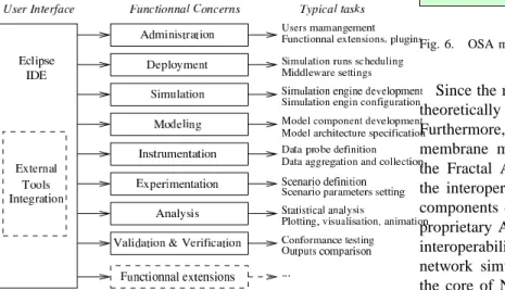
The Open Simulation Architecture (OSA)[25], [26] is a new open source software architecture intended to support the simulationists in a wide number of the activities identified in section II (figure 5).
Fig. 5. OSA functional architecture.
At the time of writing this paper, only a few elements of this architecture have been actually implemented. However, the software architecture itself relies on the CBSE principles,
3Web site at http://www.objectweb.org/.
which means that it is designed to allow the reuse of compo-nents developed for other architectures or in other contexts.
These first elements of the architecture are based on the Java programming language, and one of its derivative for As-pect Oriented Programming (AOP)[27], the AsAs-pectJ language. Since Fractal is only a specification, we also rely on one its available implementations for Java named AOKell[28].
In OSA, we applied the CBSE principles by combining two complementary technologies: the Eclipse IDE[18] and the Fractal component model. This already allows the reuse of existing components, such as a Fractal graphical component editor developed within the Fractal community. We also reused and enriched the default Fractal ADL parser with simulation concerns.
The key elements that have been specifically developed for the OSA architecture are a generic modeling API and a sim-ulation engine prototype implementation. Both are combined in a new controller plugged in the membrane of the Fractal components (figure 6). Hence, we applied the separation of concerns principle to the modeling API and engine imple-mentation. Separating these two parts from each other means that any or both may be replaced without compromising the other. As a matter of facts, in the current implementation, the selection of the actual engine implementation to be used for a simulation is done using a configuration file.
Fig. 6. OSA model component.
Since the modeling API itself may be replaced, OSA could theoretically emulate other existing discrete-event simulators. Furthermore, given that the specification of the component membrane may be provided on a per component basis in the Fractal ADL, this means that OSA theoretically allows the interoperability of heterogeneous model components (ie. components developed for different simulators with different proprietary API). We are currently investigating this kind of interoperability by developing a new API to emulate the YANS network simulator, that was recently adopted to implement the core of NS3, the next generation of the popular network simulator NS[29]. This way, we expect to be able to reuse YANS existing network components as well as be ready to reuse the future NS3 components. Given that the OSA current implementation is Java-based and that YANS is C++-based, this will also demonstrate the feasibility of reusing components implemented in various programming languages, another challenging issue of re-usability.
VI. CONCLUSION AND FUTURE WORK
In this paper we have shown that the Fractal component model is a convenient mean of applying the component-based approach in discrete-event simulation. We first identified the usual M&S activities and the main motivations and expecta-tions of the component-based approach from both the M&S point of view and the SE point of view. Indeed, we pointed out that because the initial motivations were not the same, the resulting expectations are slightly different in the two cases: in M&S, the component-based approach was primarily intended for describing the structural organization of the System to simulate, while in SE the component-based approach was primarily used to facilitate software reuse.
Then we introduced and discussed some of the key features of the Fractal component model. Separation of concerns is still very little used in M&S despite its increasing and now well established audience in the SE community. On the contrary, shared components is a feature provided by Fractal that is very uncommon. We strongly believe that shared component could noticeably alleviate the modeling process, by avoiding the hyper-spaghetti phenomenon that occur when two component deeply buried in two hierarchical components needs to interact together. Furthermore, it makes component reuse easier. How-ever, supporting the shared components feature raises several issues. First this feature is complex to implement, especially in a distributed execution context. And last, but not least, it contradicts some of the very fundamental principles of the Systems Theory, which in turn prevent using it with popular formalisms such as DEVS.
Eventually, we described how the previous concepts, and especially the separation of concerns are currently being applied in the OSA architecture. The development of this new architecture is still in the early ages. However, we hope that the very modular architecture we propose, combined with a collaborative approach of development, will favor new contributions in the OSA architecture. Indeed, OSA is not only an open platform, it is also designed to be a versatile simulation environment that users should be able to adapt or enrich according to their needs, using a similar philosophy as the one used in Eclipse.
In the near future, we plan to extend the work presented in this paper in two directions. First we want to further investigate the theoretical issue raised by shared components. Indeed, we are convinced of the usefulness of such components for mod-eling, especially for communication networks and protocols where crosscutting connections are potentially numerous.
Second, we want to investigate the technical issue of providing a full-featured model component packaging and distribution system for OSA. Ideally, this system should rely on OSGi “bundles” and repositories (the packages used for the Eclipse plugs-in) and have a content inspired from the SISO BOMS specification.
VII. ACKNOWLEDGMENTS
This work is partly co-supported by the IST-FET “AEO-LUS” project, the ANR “OSERA” grant and INRIA.
REFERENCES
[1] B. P. Zeigler, Theory of Modelling and Simulation. Wiley, 1976. [2] D. Harel, “Statecharts: A visual formalism for complex systems,”
Science of Computer Programming, vol. 8, pp. 231–274, 1987.
[3] B. P. Zeigler, H. Praehofer, and T. G. Kim, Theory of Modeling and
Simulation, 2nd ed. Academic Press, 2000.
[4] B. F. Webster, Pitfalls of Object Oriented Development. M & T Books, 1995.
[5] Corba Components. Revision 3.0., Object Management Group, March 1999, OMG TC Document orbos/99-02-05.
[6] R. Sessions, COM and DCOM: Microsoft Vision for Distributed Objects. John Wiley & Sons, 1997.
[7] R. Englander, Developing Java Beans. O’Reilly, 1997.
[8] E. Bruneton, T. Coupaye, and J. Stefani, “The fractal component model specification,” Available from http://fractal.objectweb.org/specification/, February 2004, draft version 2.0-3.
[9] J. L. Peterson, Petri Net Theory and the Modeling of Systems. Prentice Hall, N.J., 1981.
[10] Unified Modeling Language: Superstructure, Object Management Group, July 2005, version 2.0., available at http://www.omg.org/cgi-bin/doc?formal/05-07-04.
[11] Specicification and Description Language, International Telecommuni-cations Union, August 2002, standard IUT-T Z.100.
[12] E. Yourdon, Modern Structured Analysis. Prentice-Hall, 1989. [13] H. Praehofer, J. Sametinger, and A. Stritzinger, “Discrete event
sim-ulation using the JavaBeans component model,” in Proceedings of
the International Conference on Web-based Modelling & Simulation (Websim’99), San Francisco, CA, January, 17-20 1999.
[14] N. Minar, R. Burkhart, C. Langton, and M. Askenazi, “The swarm simulation system: a toolkit for building multi-agent simulations,” Santa Fe Institute, Santa Fe, CA, Tech. Rep. Working Paper 96-06-042, 1996, available from http://www.swarm.org/archive/overview.ps.
[15] OPNET Modeling Concepts & Manual, OPNET Technologies Inc., 2001.
[16] G. Wainer, “CD++: a toolkit to develop DEVS models,” Software–
Practice & Experience, vol. 32, no. 13, pp. 1261–1306, November 2002.
[17] A. Varga, “Parametrized topologies for simulation programs,” in
Pro-ceedings of the Western Multi-Conference on Simulation (WMC’98), Communication Networks & Distributed Systems (CNDS’98), San
Diego, CA., January, 11-14 1998. [18] S. Holzner, Eclipse. O’Reilly, May 2004.
[19] R. K. Jain, The Art of Computer Systems Performance Analysis:
Techniques for Experimental Design, Measurement, Simulation, and Modeling. Wiley, 1991.
[20] L. Morihama, V. Pasuello, and G. Wainer, “Automatic verification of DEVS models,” in Proceedings of the 2002 Spring Simulation
Interop-erability Workshop. Orlando, FL.: SISO, 2002.
[21] N. Oses, M. Pidd, and R. J. Brook, “Critical issues in the development of component-based discrete simulation,” Simulation Modelling Practice
and Theory, vol. 12, pp. 495–514, 2004.
[22] S. B. Lim and D. Ferry, Jain SLEE 1.0 Specification, Sun Microsys-tems Inc. & Open Cloud Ltd., 2002, final release, availble from http://jcp.org/aboutJava/communityprocess/final/jsr022/index.html. [23] F. Baude, D. Caromel, L. Mestre, F. Huet, and J. Vayssi`ere, “Interactive
and descriptor-based deployment of object-oriented grid applications,” in Proc. of the 11th IEEE Intl. Symp. on High Performance Distributed
Computing. Edinburgh, Scotland: IEEE Computer Society, July 2002, pp. 93–102.
[24] D. Deveaux and P. Collet, “Specification of a contract based built-in test framework for fractal,” in Fractal CBSE Workshop at ECOOP’06, Nantes, France, July 2006.
[25] O. Dalle, “OSA: an Open Component-based Architecture for Discrete-event Simulation,” in Proceedings of of the 20th European Conference
on Modeling and Simulation (ECMS2006). Bonn, Germany: ECMS & SCS, 2006.
[26] “Open Simulation Architecture (OSA), a collaborative platform for component-based discrete-event simulation,” Web site at http://osa.inria.fr/.
[27] G. Kiczales, “Aspect-oriented programming,” ACM Comput. Surv., vol. 28, no. 4es, p. 154, 1996.
[28] L. Seinturier, N. Pessemier, L. Duchien, and T. Coupaye, “Recent de-velopments in AOKell,” Fractal Workshop @ Middleware’05, Grenoble, France, Dec. 2005.
[29] K. Fall and K. Varadhan, “The ns maunual,” 2000, available at http://www.isi.edu/nsnam/ns/doc-stable/index.html.