HAL Id: inria-00141606
https://hal.inria.fr/inria-00141606
Submitted on 13 Apr 2007
HAL is a multi-disciplinary open access
archive for the deposit and dissemination of
sci-entific research documents, whether they are
pub-lished or not. The documents may come from
teaching and research institutions in France or
abroad, or from public or private research centers.
L’archive ouverte pluridisciplinaire HAL, est
destinée au dépôt et à la diffusion de documents
scientifiques de niveau recherche, publiés ou non,
émanant des établissements d’enseignement et de
recherche français ou étrangers, des laboratoires
publics ou privés.
OSA: an Open Component-based Architecture for
Discrete-event Simulation
Olivier Dalle
To cite this version:
Olivier Dalle. OSA: an Open Component-based Architecture for Discrete-event Simulation. proc. of
20th European Conf. on Modeling and Simulation, May 2006, Bonn, Germany, Germany. pp.253–259.
�inria-00141606�
inria-00141606, version 1 - 13 Apr 2007
OSA : AN OPEN COMPONENT-BASED ARCHITECTURE FOR
DISCRETE-EVENT SIMULATION
Olivier Dalle
Mascotteproject
I3S-CNRS/Inria/Universit´e de Nice-Sophia Antipolis B.P. 93, F-06902 Sophia Antipolis Cedex, France.
E-mail: [email protected]
Abstract— This paper describes work in progress to initi-ate the collaborative development of a new software plat-form for discrete-event simulation studies, the Open Sim-ulation Architecture (OSA). OSA is primarily intended to be a federating platform for the simulation commu-nity: it is designed to favour the integration of new or existing contributions at every level of its architecture. The platform core supports discrete-event simulation en-gine(s) built on top of the ObjectWeb Consortium’s Fractal component model. In OSA, the systems to be simulated are modeled and instrumented using Fractal components. Fractal components offer many advanced and original fea-tures, such as multi-programming language support and the ability to share sub-components. In OSA, the event handling is mostly hidden in the controller part of the components, which alleviates noticeably the modeling pro-cess, but also ease the replacement of any part of the sim-ulation engine. Apart the simsim-ulation engine, OSA aims at integrating useful tools for modeling, developing, exper-imenting and analysing simulations. For this purpose it relies on the Eclipse development platform and its ability to be extended.
I. Introduction
For modeling and simulation of discrete event systems, the component approach was introduced in the 70’s, with the DEVS formalism[21]. Indeed, an interesting property of the DEVS approach is that it allows to model complex systems by dividing the initial system, recursively and hi-erarchically, into smaller sub-systems. Since the DEVS formalism is a powerful way of formally describing com-plex systems, it has been widely used in discrete-event simulation softwares. However, DEVS do not address all the critical issues raised by component approaches. For example, as noted in preface of [22], the following critical issues for simulation have not received enough attention yet: model credibility (validation, verification, . . . ) and inter-operation (repositories, reuse of components, and resolution matching).
It is worth stressing that considering these major is-sues to be specific to the simulation domain would be too restrictive, because similar or identical issues are also being addressed in general purpose software[14]. Indeed, the ability of components to ease the process of sharing and reusing code parts is clearly an attractive property for simulation models. However, this is also a common software issue that is addressed by most general purpose component models like CORBA[16], COM[19] and Java-Beans[8].
Consequently, building a new discrete-event simulation software based on a general purpose component architec-ture could noticeably help in solving the pending critical
issues in the simulation domain. However, selecting the most appropriate general purpose component model to build such a new simulation software becomes a new is-sue. In this paper, we present our ongoing work on such a new simulation software, the Open Simulation Archi-tecture (OSA). OSA relies on one of the latest emerging component models, the ObjectWeb’s Fractal component model[5], [6].
The selection of the Fractal component model is no more than a heuristic answer to the previous selection issue. Indeed, the main design guideline of OSA is to pick as much as possible of the recent advances, emerg-ing technologies, and trends from the general software engineering solutions and to apply them and study their benefits in the discrete-event simulation context. Accord-ing to this policy, the Fractal model exhibits several ap-pealing innovative features:
• it implements the separation of concerns paradigm[1]; • it allows the sharing of a sub-component between sev-eral distinct components (the same instance of a compo-nent may be inserted inside several distinct surrounding components);
• it offers multi-programming language support: for ex-ample, components written in the Java language may be mixed (or replaced) with components written in the C++ or C languages;
• if offers advanced mechanisms to support dynamic models (creation, destruction, and mutation of compo-nents), like factories components, template components, and binding primitives;
• it offers an extensible Architecture Description Lan-guage (ADL) based on the XML lanLan-guage.
The component model is a key part of OSA, but it is not enough to build a complete architecture. In addi-tion to the Fractal component model, OSA adopts the following other elements and design principles:
• adopt both the Eclipse environment and Eclipse phi-losophy[7]: provide an extensible environment open to contributions;
• extend the separation of concern principle to the whole architecture, identifying distinct user activities and strongly enforcing a separation between these activities; • provide a model packaging and versionning system, and a repository service;
• Support distributed execution and middle-ware inter-connexion (especially HLA[12]).
Before going further in the details of OSA, let us first emphasize that most of the previous elements are not yet implemented or even clearly specified. Indeed, because
OSA is open to contributions, the OSA developments shall not (and will not) be conducted by a unique devel-opment team. In order to initiate the collaborative work process, the author’s development team currently focus on a few basic elements, such as a simple simulation en-gine and tools for components edition and assembly.
In section II we first summarize the key features of the Fractal component model used in the OSA architecture. Then, through a simple modeling case study, section III illustrates how the Fractal model helps to enforce the previous objectives. Eventually, we describe the overall architecture of OSA in section IV and some of its key internals in section V.
II. The Fractal Component Model From a software engineering point of view, a compo-nent is usually defined as “an independent unit of soft-ware deployment that satisfies a set of behavior rules and implements standard component interfaces that allow it to be composed with other components.”[2]
Fractal is the ObjectWeb Consortium component ref-erence model[5], [6]. Fractal is neither a software en-vironment nor a runtime executive. It is a specifica-tion. In other words, it is a set of rules and features that a component-based software architecture is supposed to follow or implement in order to be compliant with this model. Fractal does not mandate the use of any spe-cific programming language. On the contrary, it allows to combine component implementations possibly based on different programming languages.
The Fractal specification defines several levels and sub-levels of compliance. These sub-levels allow an implemen-tation not willing or not able to implement completely the model to state how much of the specification it com-plies with. At the lowest level, a component architecture claiming to be compliant with level 0.0 is just supposed to implement its components using the object programming paradigm. At the highest level, a component architec-ture claiming to be compliant with level 3.3 is supposed to fully implement all the features of the specification.
Hereafter, we summarize some of these key features (see [6] for the complete description).
Component external structure. A Fractal component is an object-oriented unit of code that has external inter-faces. These interfaces may be of two kinds: either client or server. The former emits service requests, the latter receives service requests. Interfaces are named. Their name must be unique for a given component but names may be reused for naming interfaces in other components. A client interface is intended to be bound to a server in-terface.
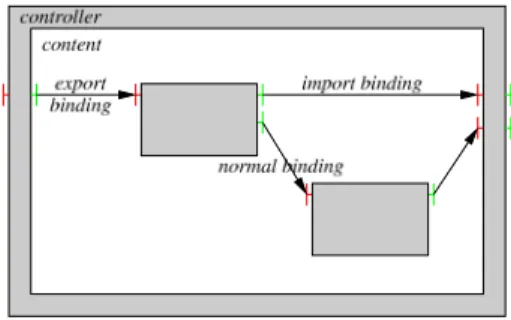
Hierarchical structure. Components may have a hierar-chical structure (fig 1). Hierarchical components are made of a controller part (also called membrane) and a content part. The content part is composed of one or more components. Since a membrane and its content recursively form a component it may have external inter-faces. It may also have internal interinter-faces. As external
interfaces, internal interfaces may be either of type client, or of type server. Internal interfaces are only available to components of the content part. A component of the in-ner part may only bind its external interfaces to external interfaces of other inner components or to the inner inter-face of its surrounding controller. Therefore, the model strictly forbids a component to bind its external inter-faces to the ones of components outside its membrane or inside its neighbouring (inner part) components.
Fig. 1: Example of Fractal hierarchical component.
Interface Introspection. Introspection is the ability for an object to collect useful information about other objects (possibly including itself). In the Fractal model, compo-nents have the ability to introspect their interfaces. For example, a component may retrieve its own list of avail-able internal and external interfaces.
Functional and controller interfaces. A functional inter-face is an interinter-face used to offer or obtain services to or from other components. A controller interface is a server-only interface. It is offered to a component to access non-functional services, such as introspection, (re)configuration, persistence, service policy, life cycle control (ability to start/stop a component), and so on. Factories and templates. A factory component is a com-ponent that has the ability to create other comcom-ponents. Fractal distinguishes two kinds of factories: generic facto-ries, that have the ability to create several kinds of com-ponents, and standard component factories, that only have the ability to create one kind of component. Tem-plates components are a special kind of standard factory components that may be recursively composed of facto-ries, and serve as a model to create normal components in a quasi isomorphic manner (isomorphic meaning the created component has the same hierarchical structure as its creator template). Since factories are components and components are created from factories, a special compo-nent is required to initiate the recursion. This special component is a generic component factory called “boot-strap”.
Shared components. The Fractal model allows a compo-nent to appear in the content of several distinct enclosing components. Such components are called shared compo-nents. This property has two noticeable consequences: (i) a component is possibly placed under the control of several surrounding controller components and (ii) a
shared component may directly interact with components located in the inner parts of several distinct components.
III. A simple modeling case study
This case study serves two objectives: (i) provide an example to illustrate the OSA modeling concepts, and (ii) demonstrate the usefulness of shared components.
In section III-A we first give a conceptual model of the system under study. Then, in section III-B, we present and discuss possible component implementations of this model with and without shared components.
A. Conceptual model
Figure 2 gives a conceptual view of our example sys-tem using a very simple form of Data Flow Diagram (DFD)[20] in which we just show data flow interactions between system entities.
Fig. 2: Simple system conceptual model.
The simple system is composed of two identical nodes that communicate with each other using the message passing paradigm. Each node of the system is decom-posed in two sub-systems: the application and the trans-port. The application sub-system, itself, is decomposed in two sub-systems: the source and the sink.
The transport sub-system implements a reliable, or-dered, connectionless, datagram routing and delivery ser-vice. It supports variable but limited datagram sizes.
The application system contains a source sub-system that produces and sends new packets, and a sink sub-system that consumes and discards the packets re-ceived.
The source sub-system simulates file transfers. It repetitively executes the following actions:
1. sleep for a random time 2. pick a random file length flen; 3. Call ⌈ f len
M AX P KT SIZE⌉ times the transport’s sending service to send fragments of at most MAX PKT SIZE bytes (the maximum packet size supported by the transport). B. Component implementations
In the following, we discuss two particular implemen-tation policies of our system example: a first one that does not use shared components and a second one that does use them.
B.1 Implementation without shared components. The first implementation that comes to mind without shared components is the one shown on figure 3. This
diagram reflects the client/server interactions between components which explains why some arrows have a re-versed orientation compared to the ones of the data-flow diagram. For example, in the conceptual model the sink component receives data while in the client/server inter-action diagram it initiates the reception service call.
The main quality of this implementation is to be struc-turally very close to the conceptual model. This good property is achieved by applying a very simple strategy in order to reflect interactions that need to cross sub-systems boundaries: replicate the client and server inter-faces of the interacting components on the internal and external sides of any surrounding membrane that need to be crossed.
Fig. 3: Component implementation without shared component
In this example, the consequence of the “replicate in-terfaces” strategy is that a node component have to ex-pose an external transport interface. Therefore reusing nodecomponents in another system model would require a minimal understanding of this transport interface which contradict the separation of concerns principle: nodes cannot be used as self-contained “black-boxes” that hide their internal implementation details.
Furthermore, it is worth stressing that the simple “replicate-interface” strategy has several other negative effects that contradict the very fundamental philosophy of component-based design. For example, let’s consider the evolve-ability good property of the component ap-proach. The component-based approach is expected to ease the replacement of a component (when new im-proved versions of the component are released, for in-stance). For example, let us consider the following possible evolution of the node component: a new sub-component modeling the physical network layer is added as shown in figure 4. Since interactions between transport sub-systems have been replaced by interactions between physical layer components, the component implementa-tion of the new conceptual model implies modificaimplementa-tions of all the surrounding components.
B.2 Implementation with shared components.
A possible implementation with a shared compoent is depicted in figure 5. In this new construct, the trans-port component is built hierarchically and contains two sub-components: the one named proxy is shared and the other, named local part is not. Indeed, the transport shall
Fig. 4: A possible evolution of the simple system
not be totally shared because the conceptual model im-plies a distributed architecture of the transport compo-nents (one instance in each node component) and this distributed architecture may have a significant impact both on the implementation of the component and on its control. For example, the transport component may consume processing time in behalf of one of its surround-ing component (the node component in this example). In this construct, the distributed part of the transport is preserved, by means of the local part sub-component, and this distributed local part may use the shared proxy component in order to interact directly with the other instances without crossing any surrounding membrane.
Fig. 5: Implementation with a shared component
As a conclusion about shared components, philosophi-cally, one may wonder whether using shared components is wise since it is a way of bypassing and somehow violat-ing the components boundaries. It is worth stressviolat-ing that in the context of simulation modeling, the isolation prop-erty of components may be considered from two point of views, which may be somehow confusing. The first point of view is the software engineering one and the second the simulation one. In [6], the authors claim that “para-doxically shared components are useful to preserve com-ponent encapsulation”. This is a software engineering point of view and exactly what we demonstrated with the simple model case study.
Let us now consider the simulation point of view.
Sup-porting the shared component modelling feature is clearly breaking the tree structure of components. As stated in the Fractal specification, the component structure with shared components may be a directed acyclic graph and bindings (interaction paths) may form cycles. Since in-teractions are eventually translated into events, shared components may imply nasty causal effects, that should be properly handled by the discrete event simulation en-gine. However, while supporting this feature may add some complexity, especially for the engine, it also opens interesting perspectives, both for the engine implemen-tation and for modelling.
The previous modelling case study gave an example of a modelling pattern in which the use of shared compo-nents may prove to be usefull. In section V, several places in the simulation engine implementation where the use of shared components may also prove to be usefull are dis-cussed. Prior to entering into the details of the simulation engine implementation, an overall description of the OSA architecture is first given in the following section.
IV. The OSA architecture
Studying a system using discrete-event computer sim-ulations imply several activities[3], [22], [13]. OSA aims at supporting a large number of these activities, which currently include (but are not restricted to) the one de-picted on figure 6.
Fig. 6: OSA functional architecture.
A typical simulation study life-cycle is made of several iterations of the three following steps:
1. the simulation preparation, which involves tasks re-lated to nearly all the functional concerns depicted on figure 6 except the analysis one;
2. the simulation execution (which belongs to the deploy-ment functional concern);
3. the simulation run(s) analysis.
Notice that during the early iterations, while the model of the system is still under development, these three steps exist in a slightly different form: the simulation prepara-tion consists in developing new models and building test scenarios, while the simulation run(s) analysis mainly consists in checking the validity of the models by com-paring the effective outputs with the expected ones.
At any iteration of this life-cycle, the OSA architecture aims at providing a strong support for the two first steps, by means of an integrated (graphical) user interface and a simulation engine. Support for the last step, analysis, may be envisaged but is not a high priority because off-the-shelf power-tools already exist for this purpose.
The OSA software architecture follows a N-tier design which may involve the following layers: a front-end user interface layer, a middle-ware executive layer, a simula-tion engine layer, a data layer for results storage, and a source code management layer for models storage and versionning.
The three first layers are described further in the fol-lowing sections.
A. Front-end user interface
The OSA architecture must provide tools to assist users in many tasks. Furthermore, the architecture should enforce a strong cooperation of these tools, us-ing an integrated and easily extensible environment. For this purpose, we selected the Eclipse platform[11], [7].
Eclipse already provides a large amount of plugs-in to assist developers in various software development tasks: specification, development in several programming lan-guages, unit testing, debugging, source code manage-ment, and so on. Some of these plugs-in are dedicated to the development of new Eclipse plugs-in, which ex-plains the ever growing list of available plugs-in, and con-sequently its ever growing popularity.
An interesting feature of the Eclipse plugs-in is their ability to be extended. Indeed the Eclipse plug-in API defines extensions points[10]: plugs-in that implement such extension points (this is not mandatory) may be extended in order to build new enriched or specialized versions of the initial plugs-in.
Eclipse plugs-in are mainly used to build new Eclipse perspectives. An Eclipse perspective is dedicated organi-zation of the Eclipse Graphical User Interface (GUI), of-fering support and specialized tools for a particular task. Therefore, the development of the OSA user interface mainly consist in providing new Eclipse plugs-in and per-spectives to support users in (possibly) all the tasks of the simulation study life-cycle. Within Eclipse, new plugs-in and perspectives may be developed concurrently, which enforces our collaborative development philosophy. Nev-ertheless, once new plugs-in and perspectives are made available for the community, this is up to each user to decide whether to install them or not.
B. Middle-ware layer
A middle-ware layer may optionally be used to support the execution of the simulations. Indeed, such architec-tures are often criticized for their potentially poor perfor-mance. Since performance is a critical issue for simula-tion, this architectural choice may be unwise. Therefore, the middle-ware layer is not mandatory in the OSA ar-chitecture, thanks to the Fractal component model: the distribution of component executions across a network through a middle-ware is an optional feature of Fractal
that may, or may not be activated, without any change in the component functional implementations (the part of components that implements models).
The OSA architecture may support the distribution of the simulation executions across a network in different manners:
• distribution of several simulation-runs, each one ex-ecuting on a single computer node. In this case, the distribution support required is very limited (a “gang-scheduler” facility);
• distribution of one (or several) simulation runs across the network, simply using the Fractal model ability to distribute transparently the execution of the components, but without any cooperation of the simulation engine. Since the minimal requirement of the simulation engine, whether it executes in parallel or not, is to ensure con-sistency of event processing between components, this implements de facto a conservative mode of parallel exe-cution[9];
• distribution of one (or several) simulation runs across the network, using the Fractal model ability to distribute the execution of the components, and the cooperation of the simulation engine. Provided the components have the persistency non-functional feature in order to regularly save their global simulation state, this may lead to the optimistic modes of parallel execution[9];
• the last form of distribution, which is somehow com-plementary of the previous ones, is achieved when the middle-ware is used to bridge together several simulation architectures, using the HLA standard for example[12]. C. Back-end simulation engine
The simulation engine is distributed over all the components that have a surrounding membrane im-plementing the simulation non-functional services. These services are accessed through a dedicated simulation-controllerinterface. Component with a simulation-controller interface are called managed components and those without such an interface are called passive components. This interface provides a uni-fied access to a simulation-controller implementa-tion. The simulation-controller implementation is not fixed. It may be totally or partially replaced.
The OSA simulation engine supports the three follow-ing semantics of interaction between components: • synchronous interactions: the service requested by the client is synchronous with the simulation time (no simu-lated time consumption);
• asynchronous interactions: the client thread is not blocked while the service is being processed, concurrently, by the server. This asynchronous mode of interaction im-plies the client shall not expect a meaningful return value from its service call;
• blocking interactions: the client thread is blocked un-til the service is completed (or aborted) by the server. The client may expect a meaningful return value from its service call.
When at least one of the involved peers is a passive component, the only interaction mode available is the
synchronous one.
The OSA simulation engine automatically translates asynchronous and blocking interactions into discrete-events, provided that both peers are managed compo-nents and thus each have a surrounding membrane with a simulation-controller interface.
The technique used to translate service invocations into simulation events was first introduced in [15]. It consists in using an object-oriented construction called a functor. A functor is the transformation of a method invocation into an object. Indeed, when a component issues a (functional) service request, through its client interface, its call is automatically intercepted by the con-troller part of the source component and reified into an event object.
This event object contains the current time in simula-tion, the event type, an object encapsulating the method called on the server side and its arguments (functor), and possibly other data that do not need to be further de-scribed.
In order to ensure a minimal inter-operability between components, the following rules are imposed :
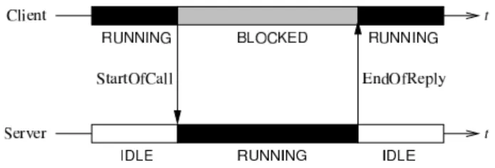
• The particular event created at the time the service call is issued by the client is initialized with a type value of SOC (Start Of Call) and inserted in the event queue of the server interface;
• In case of a blocking service the particular event cre-ated at the time the service is completed by the server is initialized with a type value of EOR (End Of Reply) and inserted in the event queue of the client interface.
V. Implementing a simulation engine in OSA As already mentioned in previous section, the sim-ulation engine implementation is located (distributed) in the simulation-controller implementations that lay in each managed component. However, be-cause Fractal supports shared components, and con-trollers may be implemented as Fractal components, the simulation-controller, and thus the whole simulation engine may be shared between all managed components. In this case, the simulation engine becomes fully central-ized.
Implementing a new simulation engine for OSA mainly consist in developing new event management policies and replacing the corresponding parts of the simulation-controller implementation. The simulation-controllerimplementation is build using three types of abstractions, each having their own in-terface: the event queues, the event schedulers, and the explicit simulation services.
Dynamic structure of models[4] may be implemented using the special factory and template components of the Fractal component model. Mutation of models and multi-models[17] may be implemented by replacing the implementation of the non-functional binding primitives of the components. This replacement is easy because the binding primitives are grouped together in a binding con-troller that lays in the concon-troller-part of each component.
A. Event queues
An event queue should be associated with each func-tional interface of a component. But since event queues are components and components may be shared, all the interfaces of a component may share the same event queue. Or some may share a common queue and oth-ers may have their own.
B. Scheduling policy
Each managed component of the simulation should be associated with a scheduler. Like queues, schedulers may be shared amongst several components. The scheduler manage the current execution state of the component. A typical scheduler would support the following states : • INIT; the component is in its initial state and awaiting for its start() service to be called;
• IDLE: the component is sleeping and waiting for an incoming request;
• RUNNING: the component is consuming processing time because it is servicing a request;
• BLOCKED: the component has issued a blocking service call and is waiting for the EOR event (service comple-tion).
A typical blocking interaction between a client and a server component is shown on the temporal diagram of figure 7.
Fig. 7: Temporal diagram of interactions during a blocking
service call.
As soon as several schedulers act concurrently, a syn-chronizing policy has to be implemented in order to en-force simulation time consistency[9].
C. Explicit simulation services
During the simulation, the functional services (the ser-vice that implement the conceptual model of the sys-tem) may use the following services offered by the non-functional simulation-controller interface of their surrounding component:
• current time(): returns the current simulated time; • terminate()/abort(): requests normal/abnormal termination of the simulation execution;
• wait until(time): • wait until(condition):
• wait until(time,condition): the current compo-nent thread requests to stay in RUNNING state until the simulation time reaches time or the condition condition is matched. New incoming service calls may still be ac-cepted by the component if the component has multi-processing capability and an idle multi-processing thread is
available. Otherwise incoming calls may be either queued or refused according to the parameters of the queue of server interface on which the call was received.
• release(condition): resume execution of a com-ponent thread waiting for condition condition to be matched. This call is synchronous (non blocking): it returns true in case a thread is woken up and false oth-erwise.
• release(condition,time): resume execution of a component thread waiting for condition condition to be matched. This call is blocking its caller thread at most until time is reached. It returns true in case a thread is woken up and false otherwise (timeout time is reached). • spin lock()/spin unlock(): primitive intended for components with multi-processing capability to ensure mutual exclusion between processing threads of the com-ponent (spinlock() blocks its caller processing thread as long as any other processing thread in the same com-ponent is not in the IDLE state).
VI. Conclusion
In this paper we introduced the Open Simulation Architecture and explained how this novel architecture could meet the expectations of a large part of the discrete-event simulation community. Indeed, the OSA architecture aims at (i) providing an open platform that supports simulationists in a wide set of their simulation activities, (ii) allowing the reuse and sharing of system models by means of a flexible component model, (iii) favouring contributions from the simulation community at any level of the architecture.
The critical issue of integrating numerous software con-tributions into a single open platform is addressed first by relying on a powerful and extensible GUI, Eclipse, whose philosophy is clearly to ease and favour such con-tributions and secondly by choosing the Fractal compo-nent model, which offers many interesting features, such as shared components and the ability to support multi-programming language. Furthermore, the Fractal model adopts the separation of concerns paradigm, which ease the process of replacing any part of the architecture, from the model components to the very core parts of the sim-ulation engine. Therefore, OSA may be used both as a testbed to experiment new parallel and distributed sim-ulation engine algorithms or as an integration platform to reuse existing discrete-event simulation models.
It shall be noted that the OSA simulation engine does not enforce the use of any particular discrete-event for-malism because the event management is kept hidden in the components non functional part. The resulting model of interactions is a classical (client-server) procedural pro-gramming model, which may serve as a basis to support or encapsulate most popular modeling formalisms, such as Petri nets or DEVS.
In order to initiate third party contributions in OSA, a detailed specification of the simulation-controller interfaces and a first implementation of the simulation engine, based on the Java language and Aspect Ori-ented Programming techniques, are planned to be
re-leased during the first quarter of 2006. This implementa-tion is based on the AOKell implementaimplementa-tion of the Frac-tal model[18].
VII. Acknowledgements
This work is co-sponsored by the french National Re-search Agency and the INRIA ReRe-search Institute.
References
[1] M. Aksit. Separation and composition of concerns in the
object-oriented model. ACM Computing Surveys, 28(4es):148, Dec. 1996.
[2] R. Armstrong, D. Gannon, A. Geist, K. Keahey, S. R. Kohn,
L. McInnes, S. R. Parker, and B. A. Smolinski. Toward a common component architecture for high-performance scien-tific computing. In HPDC, 1999.
[3] J. Banks, editor. Handbook of Simulation Principles,
Method-ology, Advances, Applications, and Practice. Wiley-EMP,
1998.
[4] F. Barros. Modeling Formalism for Dynamic Structure
Sys-tems. ACM Transactions on Modeling and Computer Simu-lation, 7(4):501–515, 1997.
[5] E. Bruneton, T. Coupaye, and J. Stefani. Recursive
and dynamic software composition with sharing. In
Sev-enth Intl. Workshop on Component-Oriented Programming (WCOP02), ECOOP2002, Malaga, Spain, June 2002.
[6] E. Bruneton, T. Coupaye, and J. Stefani. The
frac-tal component model specification. Available from
http://fractal.objectweb.org/specification/, February 2004.
Draft version 2.0-3.
[7] J. des Riviˆeres and J. Wiegand. Eclipse: A platform for
inte-grating development tools. IBM Systems Journal, 43(2):371– 383, 2004.
[8] R. Englander. Developing Java Beans. O’Reilly, 1997.
[9] R. M. Fujimoto. Parallel and distributed simulation systems.
Wiley Series on Parallel and Distributed Computing. J Wiley & Sons, 2000.
[10] E. Gamma and K. Beck. Contributing to Eclipse: principles, patterns, and plugs-in. The Eclipse series. Addison-Wesley, 2004.
[11] S. Holzner. Eclipse. O’Reilly, May 2004.
[12] IEEE-SA. IEEE Standard for Modeling and Simulation
(M&S) High Level Architecture (HLA), Federate Interface Specification. Std 1516.1-2000.
[13] R. K. Jain. The Art of Computer Systems Performance
Analysis: Techniques for Experimental Design, Measurement, Simulation, and Modeling. Wiley, 1991.
[14] K.-K. Lau and Z. Wang. A Taxonomy of Software Compo-nent Models. In 31st EUROMICRO Conference on Software Engineering and Advanced Applications (EUROMICRO-SEAA’05), Porto, Portugal, August 2005. IEEE.
[15] P. Mussi and G. Siegel. The prosit sequential simulator: a test-bed for object oriented discrete event simulation. In Proc. of 7th European Simulation Symposium, Erlangen, Germany, October 1995.
[16] OMG. Corba Components. Revision 3.0., March 1999. OMG TC Document orbos/99-02-05.
[17] T. I. ¨Oren. Dynamic Templates and Semantic Rules for
Sim-ulation Advisors and Certifiers. In P. A. Fishwick and R. B. Modjeski, editors, Knowledge Based Simulation: Methodology and Application, pages 53–76. Springer Verlag, 1991. [18] L. Seinturier, N. Pessemier, L. Duchien, and T. Coupaye.
Re-cent developments in AOKell. Fractal Workshop @ Middle-ware’05, Grenoble, France, Dec. 2005.
http://aofractal.gforge.inria.fr.
[19] R. Sessions. COM and DCOM: Microsoft Vision for Dis-tributed Objects. John Wiley & Sons, 1997.
[20] E. Yourdon. Modern Structured Analysis. Prentice-Hall, 1989. [21] B. P. Zeigler. Theory of Modelling and Simulation. Wiley,
1976.
[22] B. P. Zeigler, H. Praehofer, and T. G. Kim. Theory of Mod-eling and Simulation. Academic Press, 2nd edition, 2000.
OLIVIER DALLE is assistant professor in the C.S. dept. of Faculty of Sciences at University of Nice-Sophia Antipolis (UNSA). He received is BS from U. of Bordeaux 1 and his M.Sc. and Ph.D. from UNSA. From 1999 to 2000 he was a post-doctoral fel-low at the the french space agency cen-ter in Toulouse (CNES-CST), where he started working on the simulation of satel-lite telecommunication networks for
mul-timedia. His web-page can be found at
![Figure 2 gives a conceptual view of our example sys- sys-tem using a very simple form of Data Flow Diagram (DFD)[20] in which we just show data flow interactions between system entities.](https://thumb-eu.123doks.com/thumbv2/123doknet/13521454.417015/4.892.473.818.351.514/figure-gives-conceptual-example-simple-diagram-interactions-entities.webp)