Publisher’s version / Version de l'éditeur:
https://publications-cnrc.canada.ca/fra/droits
L’accès à ce site Web et l’utilisation de son contenu sont assujettis aux conditions présentées dans le site
Technical Paper (National Research Council of Canada. Division of Building
Research), 1961-08-01
READ THESE TERMS AND CONDITIONS CAREFULLY BEFORE USING THIS WEBSITE. https://nrc-publications.canada.ca/eng/copyright
NRC Publications Archive Record / Notice des Archives des publications du CNRC : https://nrc-publications.canada.ca/eng/view/object/?id=8af60191-f977-4c7c-9763-fad04844c003 https://publications-cnrc.canada.ca/fra/voir/objet/?id=8af60191-f977-4c7c-9763-fad04844c003
NRC Publications Archive
Archives des publications du CNRC
For the publisher’s version, please access the DOI link below./ Pour consulter la version de l’éditeur, utilisez le lien DOI ci-dessous.
https://doi.org/10.4224/20338344
Access and use of this website and the material on it are subject to the Terms and Conditions set forth at
Modular Drafting Manual: A Guide to the Application of Modular
Coordination in Design
Ser
mu'i ! l r N2l-t2 nr. 123 e . 2 BLDCMODUTAR DRAFTING MANUAL
A GUIDE TO THE APPLICATION OF MODULAR
COORDINATION IN DESIGN
Dy S. R. KBNI
A N A L Y Z E D
Technical Paper No. 123 of. the
DIVISTON OF BUILDING RESEARCH, NATTONAL RESEARCH COUNCIL, OTTAWA, CANADA
cllM/vga tq PaPuawuoc looq D - 096I
"uoL ilaN ' Kuoduo7 Eu1t1sg1qn4 ra!^aslq .'Plrolil alqDtlqoV D sPrDiloL, r'Jo4
n?4ltg uD^ 'I
,.-rcar!r1JrD aqt JoI uolrx) Io uopaatl urnullxrra puo sruauala to uoncnpotd Touoltot lo uolloulquoc n '{.71pqoa?uoqcta7u1 Eutpttotd tq 'arc1qco ot puD
s?ulppnq lo Eutddyba puD uonceo ?ql rct sqaua1a to uog1clt1sat adty puo uoltDstpropuDts
tol s60q punos D aloan o, sl ' ' ' uoltDulpto-oc nlnpow pallar-os to 1ca[qo aq1,,
PREFACE
This manual has been prepared for the assistance of those who, appreciating the theoretical value of modular coordination as a logical development in building design, wish to see how it can actually be applied in practice. In order to make the manual complete in itself, some explanation of modular principles has been included as an introduction to their application on the drawing board. More complete explanation will be found in such publications as the reports of Project
174, "Modular Co-ordination in Building", of the European Productivity Agency published in 1956 and 1961 (available from the organization for European Economic Co-operation, or through booksellers handling publications of the United Nations) and in "Modular Practice in Building", a textbook to be published by John Wiley and Sons Ltd., New York.
DBR/NRC believes that the widespread use of modular coordination in building can prove to be a most significant advance toward increased economy in building throughout Canada. Its potential in this direction will itself increase with every advance in its use, both domestically and internationally. American interest in the subject is reflected in the activity of the Modular Building Standards Association, Washington, and the previously mentioned textbook. Corresponding European interest has been centred around the European Productivity Agency project, the Modular Society in England and the newly-formed International
Modular Group.
The manual has been prepared by Professor Stanley R. Kent of the School of Architecture, University of Toronto, for DBR/NRC and with the assistance of some members of the Division's staff. Grateful acknowledgment is recognized of studies made by the working group of the European Productivity Agency project and by the members of the Modular Society, which are reflected in much of this manual and of the architects whose work is used in the examples. Comments upon this first edition will be welcomed by the Division since it is hoped steadily to improve the value and utility of the manual on the basis of its use in desigrt offices throughout Canada.
TABLE OF CONTENTS
5 The New Unit of Measure 7 The Building Process 8 Determining the Module 9 The Use of the Module
10 Components of Modular Dimension 12 Joint Faces of Components
13 Range of Modular Component Sizes 14 Modular Components in Modular Space l8 Designing with Modular Components 20 Modular Working Drawings
2l Accurate Assembly on the Job 22 Flexibility in the Use of the Grid 24 Relationship of Floors to the Grid 25 Modular Drawing Papers
26 Examples in the Selection of Planning Grids and Relationship of Components to the Grid 26 1. Metal Frame and Prefabricated Panel Walls 28 2. Metal Frame and Masonrv
32 3. Wood Frame
34 4. Wood Frame and Masonry (Brick Veneer) 36 Suggested Reading List
37 Appendix A: Definitions (reprinted from Canadian Standards Association Standard ,A'31-1959: "Code for Modular Coordination in Building")
Modular Coordination is the term given to a new procedure for simplifying the assembly of building components. It is the first attempt to resolve the basic assembly difficulties in building which are caused by the unrelated dimensions of components. Former attempts at coordination of dimensions have used for the unit of measure the size of an existing component that is frequently repeated in a building, such as that of a masonry brick. The Modular System introduces a new
unit of measure called the module - a unit 4 inches in length which is this long:
For an industry to devise a new unit of measure is not unusual. Many years ago, land sub-dividers found the inch and foot too small for convenience or accuracy and devised larger units, called the rod, chain and mile, as multiples of the smaller units. Similarly, in the building industry, the inch and its fractions are proving too small for common use and a new unit is required to coordinate the dimensions of the many building parts with simplicity and accuracy. To emphasize the idea of new measurement, United States advocates of the modular system have, since 1954, referred to it as "modular measure." No similar change in a unit of measurement for the building industry has been made since the inch and foot were established in uniform lengths by international agreement in 1875.
Traditionally, building components have been made on the site from local materials, hewn by hand to fit their required position in the structure. Materials used were those which could be worked with hand tools into sizes and shapes and placed in the structure by the craftsman or with crude machinery. Through the skill and ingenuity of the builder, components were fitted and secured in place to form walls, floors and roofs; within the spaces thus created, furnishings and mechanical equipment were installed. This trend continued up to the time of the Industrial Revolution when machines were invented that reduced much of the
handiwork in building. Improved transportation methods brought to the building
site a variety of factory-made materials and components. The craftsman was joined in his responsibility of erecting a building by the contractor, manufacturer and supplier of building materials, while the architect, formerly the master builder,
The New Unit ol Measure
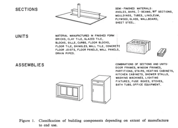
Machines have made three contributions to the building process: their fast repetitive operations have replaced the hand-shaping of components; together with advances in technology, they have produced many new components of glass, metal, plastic, wood and concrete; and they can easily handle large-dimensioned compo-nents on the building site. These three contributions, however, make more difficult the final stage in the building process - the adding of one component to another on the job. Without hand-shaping, compensation cannot easily be made for expan-sion and contraction nor erection errors rectified; the new components cannot be altered on the job by hand tools for fitting; and the larger components require an unusual accuracy of dimension and positioning on the job.
s E c T r o N s
SEMI - FINISHEO MATERIALS:A N G L E S , B A R S , I - B E A M S , W F S E C T I O N S , M O U L D I N G S , T U 8 E S , L I N O L E U M , P L Y W O O D , G L A S S , W A L L B O A R D , S H E E T S T E E L .
U N I T S MATERIAL MANUFACTURED IN FINISHED FORM: B R t C K S , C L A Y T r L E , G L A Z E O T r L E , B L O C K S , S I L L S , C U R B S , F L O O R B L O C K S , F L O O R T I L E , S H I N G L E S , W A L L T I L E , C O N C R E 1 I E F L O O R J O I S T S , F L O O R P A N E L S , W A L L P A N E L S , D R A I N P I P E S . A S S E M B L I E S
Figure 1. Classification of building to end use.
COMBINATIONS OF SECTIONS ANO UNITS: D O O R F R A M E S , W I N D O W F R A M E S , P A R T T T T O N S , S T A T R S , H E A T T N G C A B T N E T S , K I T C H E N C A E I N E T S , S H O W E R S T A L L S , W A S H I N G M A C H I N E S , L I G H T I N G F I X T U R E S , F U S E B O X E S , S T O V E S . E A T H T U B S . O F F I C E E O U I P M E N T .
components depending oD extent of manufacture
During the development of mechanization many planning and construction procedures were devised that, to some extent, provided efficient building but no procedure yet provides for the exclusive use of machine-made components.
Some procedures require careful preplanning of the assembly of components while others need little or no preplanning. When there is no preplanning, the traditional cut-and-fit procedure takes the dominant machine-made components, such as windows and doors, which cannot easily be reshaped on the building site, and adds to them others such as brick or wood siding which can be cut. This method is common in light construction where the variety of components is small and those materials cut and wasted are relatively inexpensive.
In assembly planning, drawings are made of the whole building in plan, eleva-tion, and seceleva-tion, followed by detailed drawings of the parts according to manufacturers'catalogue information on size and shape. In spite of the wide range of sizes offered by manufacturers, it is not possible to find many components that can be integrated easily as there is no over-all dimensional pattern relating the dimensions in one catalogue with those in another. Thus the planner selects components dominant in the design, perhaps those most frequently occurring, such as masonry units, or those most costly to obtain in special sizes, such as double insulating glass, and establishes sizes for the other components on his drawings so they may be manufactured to fit around these as required.
In the first method, time and material are wasted in cutting and fitting on the site where the waste is readily seen; in the second method, time is wasted in design offices with the paper work and in the factory with changing machinery to make the specially detailed sizes of components. Both building procedures are handicapped not only by the uncoordinated dimensions of components but also by the lack of a method for accurately installing the components in position.
Mechanization has brought many improvements to the building industry but it has also created new problems. These problems can only be solved by changing the small unit of measure, the inch (with its common fractions), to a larger one that will reduce the multitude of component dimensions and installation positions, that is, by introducing the MODULE.
The Building Process
Determining the Module
In selecting a dimension for coordinating the sizes of all components that might be used in every type of building, attempts were made to determine the dimensions common in the majority of existing components. Because of the vast number of sizes, however, it was not easy to find a common denominator. Such a dimension must be small enough to permit sufficient variation in the over-all sizes; if one foot was selected, doors would be 2,3, or 4 feet wide, and walls 1 or 2 feet thick. These excessively large multiples of the coordinating dimension would be wasteful of material and make economical planning impossible. On the other hand, if the dimension was too small, such as one inch, then there would be the possibility of as great a variety of sizes and erection positions as now exists.
From the rdsults of studies in difterent parts of the world, the module of 4 inches, or 10 centimeters in the metric system, has been found the most satisfactory and has been accepted in standards institutions in Canada, United States, the United Kingdom, Norway, Sweden, Denmark, U.S.S.R., Poland, Belgium, Austria, France, the Netherlands, and Germany. The lO-centimeter module is 1/16 inch smaller than 4 inches and only components of small multiples of the module can be used in both systems. There is little international trade in large-scale building components at present between the foot-inch and the metric countries; where trade does exist, components are made to each module. In Germany the lO-centimeter module is used for interior components only; exterior walls are based on a module of 12.5 cm. The two are linked satisfactorily by a system of preferred numbers. Since its conception in 1936 by Albert Farwell Bemis of Boston, U.S.A., much prac-tical development of the use of the 4-inch (10-cm.) module has been carried out particularly by the countries participating in the project of the European Productivity Agency on Modular Coordination in Building.
The word module comes from the Latin, modulus, meaning measure. Because 'module' actually does not denote a size in terms of a common unit of measurement, its use when applied to coordination in building has led to much confusion (a better name might have been a "Bemis", specifically referring to the 4-inch unit). Manufacturers can, and do, advertise'modular'desks, cabinets, and
other fitments, which by themselves fit together through some inherent measure-ments, as do children's blocks or the pieces in the game of dominoes, but the products do not bear any dimensional relationship to the other components in a building. If a 'module' is to be the denominator for the sizes of a// building components it must be an agreed size, such as 4 inches. In the Canadian Stand-ards Association Code on Modular Coordination in Building (see Appendix A) the 4-inch module has been called the "Standard" module to differentiate it from other modules.
In general, the modular size of a component is a multiple of 4 inches. This does not eliminate the possibility of dimensions other than simple multiples because either custom or manufacturing and assembly methods may require that a compo-nent have a dimension smaller than the module. It could be one half a module or one third of two modules. The most common example of these less-than-modular dimensions is given by the sizes of modular clay bricks. Owing to the manufac-turing problems of firing large volumes of clay to uniform sizes in the kiln, the height of the brick is kept less than one module so that two bricks with their joints equal 4 inches or else three bricks with their joints equal 8 inches. Each brick dimension could then be thought of as a segment of a modular dimension.
The mechanized building industry lacks uniform methods or systems for (1) coordinating dimensions of components, (2) reducing the variety of sizes the machine must produce, and (3) installing components more accurately. The larger unit of measure, the 4-inch module, provides one system'for all purposes. It determines reasonable intervals of 4 inches at which components of modular size may be coordinated. It eliminates, in the main, the sizes between the 4-inch intervals for simplicity in machine operation and thus the range of sizes is small. It also provides a space grid with control points or stations at 4-inch intervals at which components may be accurately placed and checked in position.
The Use ol the Module
Components ol Modular Dimension
In sizing components by using the module, nominal dimensions in multiples of 4 inches are established, giving the modular dimension of the components. From this initial step, a uniform procedure is laid down for manufacturers to follow in order that different components, when added together in a building, will total modular dimensions. The procedure recognizes two facts: (1) all components must be joined with (or separated by) a ioin1 (2) components may vary from the manufacturers' 'intended' size to a practical oversize or undersize as a result of uncontrollable or unpredictable physical changes in the material during manufac-ture, expansion or contraction due to temperature or humidity, or lack of precision manufacturing machinery. Taking both these facts into consideration when devis-ing the usable size of a component is a new idea.
In standards of the Canadian Standards Association, the Canadian Government Specifications Board and those of trade associations, manufacturers and builders have already agreed on reasonable deviations from the intended or manulacture dimension which are in keeping with good building practice and quality manufac-turing. Through job experience manufacturers and builders know the desirable size and acceptable maximum and minimum sizes of the joints required by the various components for sound construction.
The procedure of modular dimensioning simply stipulates that the sum of each component and its joint should never be greater than a multiple of 4 inches. This applies even when the component varies to its maximum manufactured oversize limit and the joint is at minimum acceptable size. Similarly the sum of each component and its joint must never be less than a multiple of 4 inches when the component varies to its minimum manufactured undersize limit and the joint is at its maximum acceptable size.
MODULAR DIMENSION MANUFACTURE DIMENSION JOINT UPPER LIMIT DIMENSION MINIMUM JOINT DIMENSION LO\'VER LIMIT DIMENSION M A X I M U M J O I N T DIMENSION TOLERANCE DEVIATION ACTUAL DIMENSION MODULAR CLEARANCE
THE OIMENSION FROM THE I{ODULAR RANGE
THE DESIGN SIZE 0F A COiIPONEI{T As sHowN IN THE MANUFAGTURER.S
CATALOGUE lir:rii r.i :i'. i...:::. i ...'.i:. ;:: :.::i:.j::::i:: i i :1
THE TOTAL CHANGE IN THE MANUFACTURE DIMENSION THAT CAN B E T O L E R A T E D
THE SMALLEST DIMENSION TO WHICTI THE MANUFACTURE DIMENSION MAY DEVIATE AS THE JOINT HAS CORRESPONOINoLY DEVIATED FROM ITS DESIGNED SIZE TO ITS MAXIMUM USEFUL SIZE
ll--l
iirr-ffil1
L-
--l
ffi
THE AMOUNT OF CHANGE FROiI THE MANUFACTURE SIZE TO THE LIMIT DIMENSIONS
THE SIZE OF THE COMPONENT AS IT ARRIVES ON THE JO8. IT MAY BE A N Y S I Z E W I T H I N T H E L I M I T DIMENSIONS
THE DISTANCE BETWEEN ADJOININo COMPONENTS
Ioint Faces of Components
It is not sufficient for a component to be simply of modular size to ensure coordination with another component; the problem of jointing must be taken into account. Their joint faces cannot be designed for just one type of installation but may need modification to allow satisfactory relationship with adjoining ones. As more and more joint surfaces are designed with interchangeability in mind and good joints are devised, joint details can be standardized and repetitious design efiort eliminated.
D O O R F R A M E T O D O O R F R A M E
D O O R F R A M E T O B R I C K W O R K
D O O R F R A M E T O S T U DP A R T I T l O N
D O O R F R A M E T O W I N D O W
Figure 3. Characteristic profiles of joint faces of components.
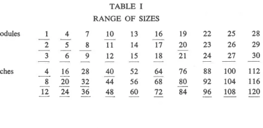
The range of sizes that a manufacturer produces must be limited in extent for economy. On the other hand sizes must be such that they will readily fit others in the building and also provide sufficient flexibility in the arrangement of components so that variety in building design is possible. A range of sizes based on multiples of the module from 4 inches to 10 feet (1 module to 30 modules) provides a limitation without hindering either coordination or flexibility.
TABLE I OF SIZES Modules 1 6 t 7 1 8 88 100 lr2 9 2 1 0 4 1 1 6 96 108 120
Components need not be fabricated in the full range but rather sizes should be selected approximately corresponding to those in common use. Where flexibility in the arrangement of components is desired, sizes from the lower end of the range such as 4, 8, 12 and 16 inches are preferred. It is also helpful if, when the dimensions selected are doubled or tripled, they can fit dimensions that are higher up in the range (12 and 16 fitting into 48). Those shown underlined in Table I are considered most usable.
A range of sizes can be reduced to a minimum by including only those dimen-sions that create components of aesthetically pleasing proportions, those most prac-tical for manufacture and installation, and those dimensions such as door, desk and ceiling heights that are best suited to anthropometrical dimensions. For example, Swedish door components (door and door frame) are in two modular heights, 6 feet 8 inches and 7 feet, and in four widths, 2 feet 4 inches, 2 feet 8 inches, 3 feet 0 inches and 3 feet 4 inches.
Range ol Modular Component Sizes 1 9 20 2 l t 4 7 2 5 8 3 6 9 Inches 4 1.6 28 40 52 64 76 8 2 0 3 2 4 4 5 6 6 8 8 0 12 24 36 48 60 72 84 RANGE 1 0 1 1 T 2 t 3 t 4 1 5 22 25 28 23 26 29 24 27 30
Modular Components in Modular Space
The modular range is applicable to the length, width and thickness of a component. It may be used in all three, as in concrete block 8 by 8 by 16 inches
(or 2by 2by 4 modules, abbreviated to 2Mby 2M by 4M), while in other compon-ents, only two dimensions may be modular and the third non-modular such as glass thickness which is a non-additive dimension.
Where components are necessarily smaller than one module, they may be grouped to form a modular multiple, as is common in brickwork. Three units are added to form 8 inches or again three units to 16 inches. Each unit is a segment of the modular multiple resulting in a segmented range.
TABLE II
SEGMENTED RANGE, IN INCHES (This range is common in masonry for coordination at 2M or 4M multiples.) 22/s lovs 182/s 262/e 342/s St/s l3rA zlVs 29Vs 37t/s 8 1 6 2 4 3 2 4 0
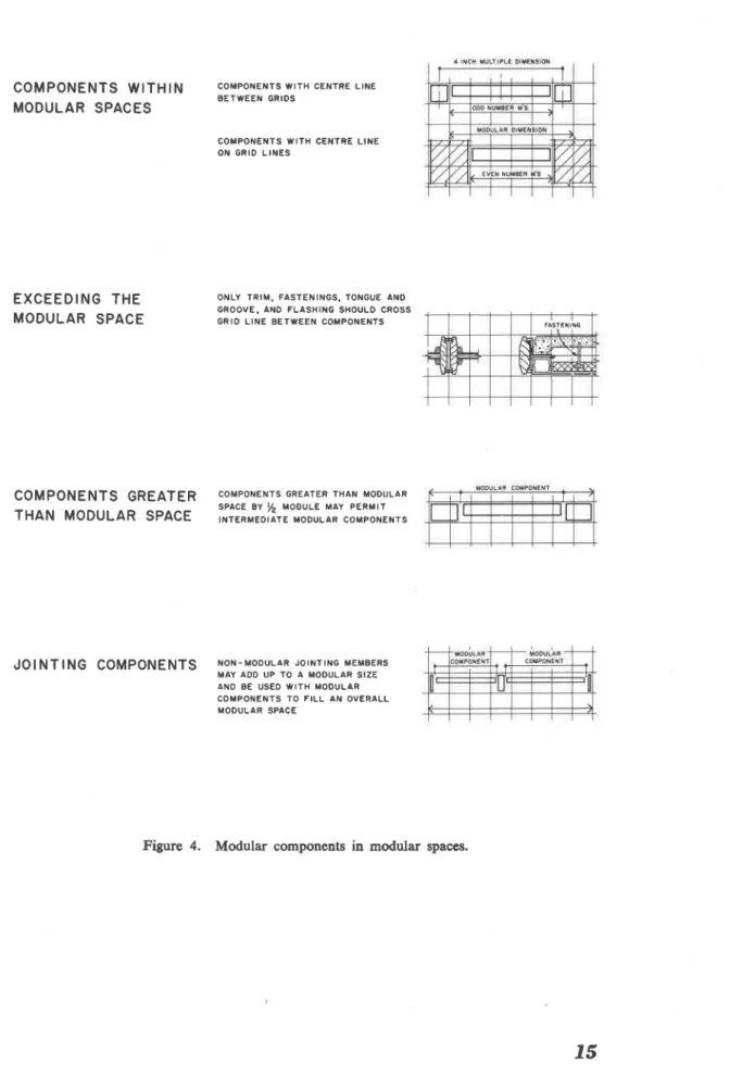
Since each modular component and its joint do not exceed a modular interval, the component can be visualized as occupying a modular space. In general, the component is assumed to be located in the middle of its modular space. There-fore, no component normally penetrates the modular space of another component. This does not prevent such parts of a component that are necessary projections of the component's fastening arrangement such as tongue and groove, or flashing required to keep out the weather, from exceeding its modular space.
For structural strength, a component may have to be larger than a modular dimension. If the excess can be an even one-half module then an intermediate modular component can be placed between and order readily restored.
C O M P O N E N T S W I T H I N M O D U L A R S P A C E S E X C E E D I N G T H E M O D U L A R S P A C E C O M P O N E N T S G R E A T E R T H A N M O D U L A R S P A C E J O I N T I N G C O M P O N E N T S O N L Y T R I M . F A S T E N I N G S , T O N G U E A N D G R O O V E . A N D F L A S H I I { G S H O U L D C R O S S G R I D L I N E B E T W E E N C O M P O N E N T S C O M P O N E N T S W I T H C E N T R E L I N E B E T W E E N G R I D S C O T ' P O N E N T S W I T H C E N T R E L I N E O N G R I D L I N E S N O N - M O D U L A R J O I N T I N G M E M B E R S MAY ADD UP TO A MODULAR SIZE A N O B E U S E D W I T H M O O U L A R C O M P O N E N T S T O F I L L A N O V E R A L L T,OOULAR SPACE
$#
C O M P O N E N T S G R E A T E R T } I A N M O D U L A R SPACE BY !/2 MOOULE MAY PERMIT I N T E R M E D I A T E M O D U L A R C O M P O N E N T S
The space occupied by a component is in reality three-dimensional and so control is needed in each dimension. The controlling planes are called a space Crid. A modular space grid imposes control at 4-inch intervals. Most conditions in modular assembly can be solved two-dimensionally, thus the space gnd is projected horizontally and vertically, in the same manner that all objects are projected in working drawings, registering as a modular grid of modular lines.
If the space inside and outside a whole building is visualized as penetrated by the modular space grid, the new system for coordination is apparent. The con-trolling planes of the grid denote the size and position of the building structure, thus completely fulfilling the requirements for efficient building with machine-made components. Variation ol component size is limited by the 4-inch module. Components are accurately placed by having predelermined locations in the grid.
3 - D I M E N S I O N A L S P A C E G R I D 2 . D } M E N S I O N A L P R O J E C T I O N B A S I C M O D U L A R G R I D O F 4 I N C H E S P L A N N I N G G R I D S T R U C T U R A L G R I D T H E S P A C E O F A B U I L D I N G I S B A S I C A L L Y O I V I D E D I N T O 4 I N C H ' c u e e s ' R E p R E S E N T E D r N o R T H o c R A p H t c p R o J E c r t o N A S G R I D L I N E S A T 4 I N C H E S . T H E N E X T L A R G E R D I V I S I O N I S T H E P L A N N I N G G R I D D E T E R M I N E D B Y T H E P L A N N E R F R O M T H E S I Z E O F C O M P O N E N T S O R B U I L D I N G F U N C T I O N . T H E L A R G E S T D I V I S I O N O F S P A C E I S B Y S T R U C T U R A L M E M B E R S O R M A J O R B U I L D I N G E L E M E N T S S U C H A S F L O O R S A N D W A L L S . Figure 5. The volume of a building divided into modular spaccs by the grid and itg
Designing with Modular Components
In stepping from the design of components to the design of a building the same modular grid is envisioned. Whereas formerly it penetrated through one compon-ent, it now penetrates the whole building and may further penetrate the space outside the building if desired. This change to a larger scale is accompanied by the introduction of larger grids called planning grids. The module that determines the grid is a multiple of the standard grid and is obtained from the size of a large modular component which is dominant in the building, such as a curtain wall panel, office partition panel, or precast concrete structural floor unit. On the other hand, the planning module may be a functional dimension for relating activity spaces. In many cases the one planning grid will serve both purposes.
The largest form of controlling grid is a structural grid for setting out the members in skeleton frame construction. The modular grid is uniform in dimen-sion in all three directions, i.e., I module; all other grids may be of various modular dimensions depending on components and functions. Furthermore different grids may be utilized in the one structure, overlapping each other to form a tartan pattern of grids.
There are unlimited combinations of grids and it should be remembered that they are to be used as flexible planning tools. A single grid should not be set and every component forced into it: this would undoubtedly result in poor, sterile design. Grids are controls with many settings, although each setting is at the interval of the standard module to ensure coordination of components.
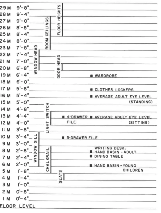
Designers have often worked with grids on the horizontal plane in achieving efficient use of floor space and room relationship, but little consideration has been given to the advantages of vertical grids. They are much simpler to use than the horizontal because the possible dimensions are few. The most important of these are the heights of ceilings, window sills, window heads and door heads, and table heights. In each group the dimensions are fairly constant for each building type as they have been determined by building regulations, local practice and custom, or the dimensions of the human bodv when at rest or in motion.
2 9 M g ' - 9 " 2 g M g ' - 4 " 2 7 M g ' - O " 2 6 M g ' - 9 " 2 5 M g ' - 4 "
24 M 8'- o"_
23 M z'- 9"
2 2 M T ' - 4 "
2 l M z ' - o "
zo M 6'- 9"
l 9 M 6 ' - 4 "
t B M 6 ' - o "
1 7 M 5 ' - 9 "
1 6 M 5 t - 4 t t l a v E R A G F A D l r r F y F I F v F l q F -9 lrl -G o o J l! I W A R D R O B E r C I O T H t r q I f 1 N X F t r Ql s M 5 ' - o " _
-14 M 4'- 8"-
P
13
M 4L4"_i
t2 M 4'- o"_
!
l l M 3 ' - 9 "
9
ro M g'- 4"_ i
9 M 3 ' - o " - f
I M 2 ' - 8 " - E
7 M 2 ' - 4 " _ ? 6 M 2 ' - o " 3 5 M l ' - B " H A N D B A S I N A O U L T -I D -I N -I N G T A B L E C H I L D R E N ( S T A N D I N G I J Ja
E Y J I (, 4 M l'-4" 3 M l ' - o "2 M o ' - 9 "
I M o'-4"
F L O O R L E V E LFigure 5. Vertical planning dimensions related to the module.
Modular Working Drawings
In preparing the modular working drawings for a fully designed building, the three customary types of drawings are required: preliminary sketches, assembly working drawings, and detail drawings.
From the beginning of the design process and as soon as the structural material for the building has been established whether it be concrete frame, steel frame, wood stud or load-bearing masonry, consideration must be given to the modular gnd, a planning grid and a structural grid. As the preliminary sketches are at a small scale, l/32, l/16 or l/8 inch to the foot, and without detailed dimensions, it is usually sufficient that the scaling of wall thicknesses, floor heights, repetitive openings and recesses, projections and changes from one material to another, centre-lines of columns and over-all dimensions be modular dimensions. If modular control is exercised in the early stage by the designer then subsequent modifications in relating building components to the modular grid are minor, and design of the building is unchanged. The designer should not ignore the control imposed by the modular grid but rather accept it as a natural characteristic of the machine-made building components he is using.
Following the preliminary sketches, assembly working drawings in plan, eleva-tion, and section atI/16, 1/8 or l/4inch to the foot, are usually begun. They
T H E S E A R E S T A N D A R D M O D U L A R W O R K I N G D R A W I N G S
t^t coNFoRilANCE W|TH THE COOE FOR UODULAR CO-OnUMTtOIit N AUtLOtltG -C,A'A'3t't959 T H E P O S T T T O t { , A r D U S U A L L Y T H E S I Z E O F E U I L O I N G C O M P O N E N T S IN T H E S E D R A W I I { G S A R E C O N T R O L L E D B Y T H E S T A N O A R O I ' O D U L A R G R I O O F 4 I I { C X E S . T H E L A R G E S C A L E O R A W I I I G S S H O W I N C L E A R O E T A I L T H E F I 1 T I N G O F C O i l P O T E N T S T O T H E G R I D . T H E S M A L L S C A L E P L A N A N O E L E V A T I O N SHOW ASSETBLY OF COTPONENTS. I { O S T O F T H E O I M E N S I O N S G I V E N A R E I ' O D U L A R O I I ' E N S I O N S R U N N I N G T O C O I { T R O L L I N G G R I O L I N E S A 1 { O A R E I N I { U L T I P L E S O F 4 I N C H E S . B Y A P P L Y I N G T H E A R R O W H E A D C O N V E N T I O N I T I S C L E A R W H I C } I D I T E N S I O N S A R E T O G R I O L I l { E S . D I I | I E N S I O N L I N E S T A K E N T O T H E 6 R I O A L W A Y S }IAVE AN ANROVHEAO D I M E ] { S I O N L I N E S T A K E N T O P O I N T S N O T O N T H E cRlo ALTAYS trlve A oof ---{
T H E D I M E N S T O N S O F T H E I ' A i l U F A C T U R E D C O M P O N E N T S s x o w u rN T H E L a R G E s c A L E o € T A I L l s l s T a l n o z s T a ARE fAE TAilUFACTUNE OITEIISIOIIS.
IHE 'IOOULAN OilIETTSD'IS OF THESE COMPONENTS ARE c o N s r D E R E o A s 4 ' A N D g ' :
1 6 g 1 4 i o r u e t s r o N r s r H E c o N s r A N T R E L A T t o N S H I P or rxeie PARTTCULAR coMPoNENTS ro rHE
C O N T R O L L I N G G R I O .
20
should not be started, however, until the exact modular relationship of the main building elements (floors, walls and roofs) to the modular grid are known, either by experience or by working out large-scale details lVz or 3 inches to the foot.
Large-scale details are required, therefore, to play another role in addition to their former ones. They become important key drawings: not only do they show clearly the size and joining of components, but they also show the relationship ol the components and building elements to the grid. With this use of detail drawings, assembly drawings usually need only contain dimensions to grid lines -dimensions which are non-fractional, easily-added multiples of 4 inches. Also, because of this concept, assembly drawings can be at a smaller scale than normally required to show fractional dimensions, and have been satisfactorily made at l/1,6 inch equals one foot. To inform readers of modular drawings that they have been prepared by the modular system, an explanatory note similar to Fig. 7 may be placed on the first page of the set of drawings.
Errors in assembly may be caused by wrong dimensions, illegibility or in- Accurate sufficient and ambiguous points of reference on the drawings. These errors must Assembly on be eliminated in building with machine-made components where cutting and fitting the lob cannot be relied upon for making corrections. The modular components are sized
with great care not to exceed their modular space and for correct assembly without site adjustment, their modular spaces (as defined by the grid lines) must be accurately located on the job. The modular system with its modular space grid provides many points easily established for such accurate assembly.
The draftsman will select and define the principal reference grid lines and dimension them clearly (non-fractional) on the assembly drawings. Other grid lines not required for locating components need not be shown. This elimination of the squared grid pattern of lines on the drawing could lead to a confusion of grid and non-grid lines and so a 'drafting convention' for modular drawings has been devised. The convention applied to the dimension lines stipulates: when a dimen-sion is given to a grid line, the dimendimen-sion line is terminated with an arrowhead; when the dimension is given to an off-grid point (surface or line), the dimension line is terminated with a dot. This simple device is used on preliminary, assembly, and detail drawings. It might be thought convenient if modular drawings could
Flexibility in the Use of the Grid
It must be recognized that the modular grid is used as a "working tool" to assist in positioning locating components. Like any tool, with experience its use will become more varied. Two variations are suggested, one breaking the con-tinuity of the space grid and the other permitting components to come out of their modular spaces.
There is some building construction that will have modular components, such as brick, related to the basic modular grid, then a non-modular component such as strapping, lath and plaster, is added to the inner face resulting in the face of the plaster not being on the grid. For convenience of placing interior modular cabinets or partitions, it would be desirable to have the face of the plaster at a grid. This can be achieved by breaking the continuity of the basic grid used to locate the wall components, and introducing a new secondary grid system beginning at the face of the plaster. The space between the two grid systems is called a Neutral Zone. Any reasonable number of secondary grids may be used to allow for non-modular components but their relationship to the basic grid, that is, the width of the neutral zone must be clearly shown. In this way the building can be divided into many fully modulated volumes, separated by neutral zones, and interior planning with modular components made possible.
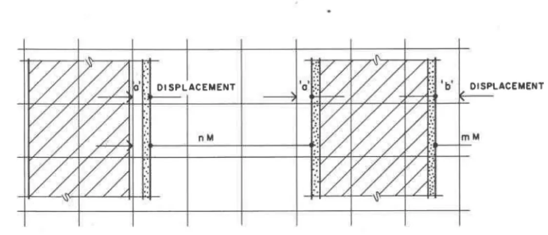
The other procedure for combining modular and non-modular components in the foregoing construction is called the Displacement Principle. In this method, the basic grid is retained throughout and the modular components become 'dis-placed' from their modular spaces by the non-modular wall thickness. The amount of displacement must be carefully noted (as was the neutral zone) as all modular components located in relationship to the face of the plaster will be equally displaced from the grid.
D I S P L A C E M E N T
D I S P L A C E M E N T
22
C O N T I N U O U S G R I D W H E N P O S S I B L E T H E N E U T R A L Z O N E S H O U L D B E A S I M P L E F R A C T I O N O F T H E M O D U L E e g . O N E - H A L F T H E N E U T R A L Z O N E I N T H E V E R T I C A L G R I D P E R M I T S M O D U L A R B L O C K tN T H E F O U N D A T T O N r O F I T I N T O O N E G R I D A N D F O R W A L L C O M P O N E N T S B E G I N N I N G A T F L O O R L E V E L T O F I T I N T O A N O T H E R G R I D N E U T R A L Z O N E Jk nM + 2M * mM + 2M >ll+_
Relationship ol Floors to the Grid
The thickness of floor elements is an uncontrollable variable because of the numerous materials, and the spans and loads involved. Thus uniform floor-to-floor heights cannot be the result of uniform ceiling heighis plus a uniform floor-to-floor element thickness. The custom in modular design is similar to the conventional, in which the floor-to-floor height is constant (or connecting flights of stairs would difter in treads and risers) and either the ceiling heights vary with different floor thicknesses or the ceiling height be constant and the floor be built up by furring to a uniform thickness. Modular design further requires that the floor be related to a grid line.
Whether the finished floor surface or the rough structural floor surface be related to the grid depends on
( 1) the use of modular components above the finished floor line, and (2) the sequence of construction.
In both cases it is most important that the selected floor surface not exceed its modular space. Many U.S. examples show the floor surface Ve inch below the grid line as a construction tolerance to ensure this principle.
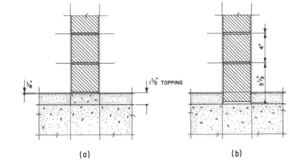
In Fig. 10(a) modular masonry units are exposed above the finished floor so coursing must begin with an exposed joint at the floor level. As the finished
( o )
Figure 10, Alternate methods structural floor.
( b )
of setting first course of modular masoDry on rough
flooring will be a topping on the rough structural floor, applied after the masonry work, a stool or curb must be provided for the masonry units the thickness of the topping. It may be concrete or a thin masonry unit. Alternatively, the first course of masonry units may be a special height obtained from another range of sizes as shown in Fig. 10(b). Figures 12 and 15 show the position of a slab with integral topping.
When constructing wood-frame buildings, wall components are erected directly on the wood subfloor and shimming to finished floor surface level is impractical. Thus the floor grid is placed at the surface of the wood subfloor (Fig. 9). Finished flooring materials applied to wood subfloors are usually 3/a inch and less, an 'encroachment'that can be tolerated by the modular space of components placed on top of the floor.
Not only are dimensions of interior modular components taken from the floor grid, but also components in the exterior walls such as door frames, thresholds, and window frames, and precast or preassembled flights of stairs.
The experience of many draftsmen indicates that tracing.paper with faint grid lines printed on it is not essential; some find the squares distracting. A grid cover sheet on the drafting board, or a grid paper which can be slipped under the tracing paper, may be convenient at times, but a grid scaled oft as required is usually sufficient.
Modular Drawing Papers
EXAMPLES IN THE SELECTION OF PLANNING GRIDS
AND RELATIONSHIP OF COMPONENTS
TO THE GRID
1. Mprer. FnerurB er'ro PnSTABRTcATED PeNBr- Wer,m
The Britisk Standards Institute Laboratory, Hemel Hempstead, England.
Architects: Bruce Martin and lohn Weate
These laboratory buildings were designed on a completely modular basis as one of the United Kingdom's test buildings under the Second Phase of the European Productivity Agency project. In selecting the size of the planning grid, the architects Bruce Martin and John Weate, considered dimensions from 6 to 12 rnodules. The module 6M was too small for a building of this area and 12M was too large for the planning of small offices and for flexible arrangement of laboratory equipment. The choice for the planning grid was thereby narrowed down to 8M.
Two structural grids were used: one for the single-story office, 24M by 4OM / l6N'4 / 40M, as shown in Block B; the other for the story-and-a-half testing rooms, 32Mby 25M / 36M / 25M as shown in Block C. Two sizes of columns were necessary for the different roof heights. The smaller column was designed to fit into one modular space, the larger into a space-and-one-half. Their position relative to the grid was also varied as shown on the large-scale detail in Figure 10.
The use of a site grid of 48M over the whole building site was found useful in the placing and erection of the building and in grading the site.
P R E L IM IN A R Y
S K E
T C H
PLANNING GRID 8 M STRUCTURAL GRIOS1--t-t-t-f t-f
BLOCK B 24$r4O)t/|Gln/4OM -BLOCK C 32ur25v'/36i/,/?5iI
+
--1
B R I T I S H S T A N D A R O S I N S T I T U T E SITE GRID 48MA S S E
M B L Y
W O R K
I N G
D R A W I N G S
D E T A
I L W O R K I N G
D R A W I N G S
Figure A R C H I T E C T S B . M A R T I N A N D J . W E A T E 36 MM G L I N E X ASSESTOS EOARD C O L U M N B L O C K B C O L U M N B L O C K C11. The three types of drawings for the Testing Laboratory of the British Standar&
2. Mprer, Fnaup et.to Masounv
Medical Center, University ol llest Virginia. Architects: C. E. SiUing and Associates
In this structure only the standard grid was used to locate all building elements. No structural or planning grid is evident although order has been imposed by repetition of many like dimensions. The modular brick unit is the dominant component and all dimensions in the structure are set for the economical use of this component.
On the floor plan (Fig. 14) diawn at l/16-inch to the foot, almost every dimension is a multiple of 4 inches. No fractions are involved as all dimensions are to grid lines. The vertical section through the wall (Fig. 15) clearly shows the relationship of the brick units to the grid line. Floor elevations from the datum point are given in modular dimensions. Vertical coursing of masonry is dimen-sioned with the uncommon fraction of. Vs inch or 2/s inch as the result of using brick units belonging to a segmented range of sizes (see Table lI, p' l4), in addition to being numbered (See also Fig. 16). This does not confuse the brick mason who is working with hi$ story-pole laid out three courses to 8 inches.
L l * Ft+ow
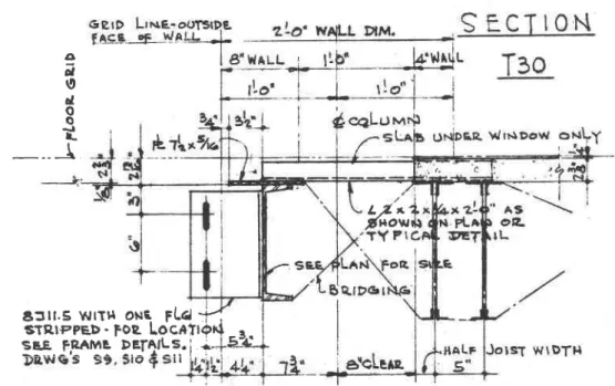
Figure 12. Structural detail showing dimensional relationship of steel framing to the modular grid. Scale Vz" - l'-0" (Medical Center, University of West Virginia).
28
AE
0 .l o o L I _ - - _ _ 3 t3tr.s wtTH oNt FLA { I STP,TPPED-FOE LOCATTO|$ e_ |:!+. f,!A!l PFrtr!:..
i --i-sJ-t
$ !
{t-: t c ?rlt oF tlt 9. t21 tz ItT;7f
l g u 4 " . lt t l x l €J '
Tlo ;J ]
'f 30 I 5l? F . R A r t ' i B M l ( L - D R A w l N g l l l I 297!+1_ _ I $ F I O O I t - : F - r 4 Z 6 i ^ 8:zlr.:J s:btd j ?iT.tf, ii fB[?,?!'s] =i
a oiJ3iit'caD i +i+' 3ig. 4rs atai'
S E E
F I G 1 2
? 1 L t o S , ? ( l S J l r 7 | b(G)
Figure 13. ,-tJ)r E
Third floor plan showing fourth floor framing. (Top below fourth floor grid unless noted. Figures thus from fourth floor grid to top of beam.) Scale 1/16" University of West Virginia).
re_
)
'_&)
of afl beams to be s/e" (-).s/a") indicate distance = l'-0" (Medical Center, :z_t.) _f3- ?g) 7.6' w{,. s-?'Mlra
::rfi
-Wrr.F eggs-9.?.ri|i2 wi'r'f,r!r ! i F'!'
ia a I i F t? 7 w 4 ' & 1 . M : 1 4 _c3_ (qf) w a . l . M : t g @ l-li.rf-f i a 7ffJT'.,@
a . b i 3 . r . M l r + | r ' tft.-i,-l
r;.a
I
*,9
I ---r ,L--i - | +-+ -., --.llxqLr\zlo F:c,rrsq TrLr.+
t I tlct.tt? I{'LLN"TJ TILE @t}|3Br*rxroLals* traB of mrouslrcrr urrtT.
sFse roa rt|oriq|oN uNtT (:ra utcr) ;
;AsexrLl liLG
4T[ F[. 6r|D 3L.
lt16:o-- lt16:o-- lt16:o--FL^STER
buLlxose. TrLa -Conxee. LJN6.LAz.eo Frc.rN<. TrLe.
brgenr*cir 4*r!Le (see ueex) Plrslre 3uc.FAc,r.o Wrxoow Slaot
-t-tLltra:cfa:l!1!:cB7
CeflIrNlbua cL. iloa:o" Goxyrr **,,uo$rwm.
rtrl. Frne { wnm Ib i
r{i I td |rsuLalor.r Brcx. or lnu.rclrcrr.r tltrl Asex,rLy TrLr. i o:o FL. cuo t. n*'dl o s . - . . . - l cD|fr[.ruo|,6bre cYlrt ?'tl+ colr3tE
---_{h.aLrz.ro Frcrucl TrL:
.'-r
Figure 15. Vertical section of west exterior wall. In this drawing the pattern of 4-inch grid arrowhead dimension lines shown. The dimensional relationship of masonry to the grid is also omitted because masons were thoroughly familiar with modular dimensioning for modular brick. (Medical Center, University of West Virginia).
,f F!71?e
Ecni? c?to eL. tz26'.8"FUTUTE rTA FL. ac.ro eL.1216"6"
clnile EL; lagtl?{
',L ---'2 Lr.
I cD?|r|q 3L. ilt4:d
I /-4$l FL- aGD aL. ll76io'
t
-EL. l|66;0'
€ct9 !,L. ||36:d
edr. oF L$rror tfil3,3Lll.lr:d l/Cn..'L!zeg &t<Y.
i , ..,l|ArDrlocrus @l -f4 i.s'Bt.ctt E, r a ?fle FL. €gte EL lrs4lcr t - I l,X Fr- *D rL. lt4z:€r bi d
I
it;
d i- t L - , I r r r - - ' 1 , i - . r L - - : i - - 1 . ' F -t - . r t - j i - - . - . r+
i ore fL css _c!:1tz_?i_.: t oFtxa EL. lltrt" ltofi 4. iltoia'3. Wooo Fneun
Mark 3 Experimental Project.
National House Builders Association. Architect: S. A. Gitterman
The basic location of a wood-frame wall within the grid is determined by centring the studs between two grid lines as shown in Fig. I7 (a). This may be varied to satisfy different construction techniques and as the designer becomes more familiar with the use of the controlling grid.
In the example, the dominant construction components are sheets of cement-asbestos cladding and gypsum-core wallboard. These components have been utilized in their full four-foot width or in half-width. Interior partitions are l3/e inch laminated gypsum wallboard centred between control lines at half-module spacing, Fig. 17(b). Windows in this experimental house are fixed glass, but modular window frames could have been installed in the openings. The use of dimensions without fractions presents a plan which can be easily read. To work accurately from the modular plan when laying out his structure the builder only needs to keep in mind the few fractions clearly shown on the large scale details.
1 7 o
Figure 17. Relationship of exterior wall and interior wall to grid.
t 7 b
r 2'-ol1 2Ldt 2'-d'
I
ldl
l =
I J
I
r'-N -, lro
tot- o"
ltri,d'-I,.'-4
ill
-o _ l rf) _ l f I eEFSE I I4. Wooo FneuB aNo MesoNnv (Bnrcr Vexnen) Modular Experimental House, Ottawa.
Architects: Gilleland and Strutt
This example is similar to the metal frame and masonry building with only the 4-inch grid exercising control in the placing of all components. The foundation wall was designed in modular concrete block and so the blocks were the first component to be set out on the job. For greatest convenience, their customary location relative to the grid, which is the outer face one-half joint from the grid was used. The brick vqneer was then placed in the same relative position to the grid. Having thus set the location of the dominant components, a position for the wood frame was established. The large-scale detail of the corners (Fig. 19) shows the position of the wall components to the grid and it will be noted that the wood frame is centred about a grid line. This position of wood stud walls to the grid is retained throughout the job.
On the floor plan (Fig. 20), some dimensions are given to the grid line at the outer face of the masonry while others are given to the grid line through the centre of the wood frame. The draftsman should always keep in mind the order in which the components are to be assembled and provide usable dimensions for every trade.
Figure 19. Large-scale detail of corners of wood-frame brick veneer and masonry foundations (Modular Experimental House, Ottawa).
1 6 " t ,,/,, ,//
K,
,t{
.-Jt
f$
)lw
/)l(/
4tw
/ 34tB E P R O O M
g E V 2 0 0 M
tLtt
k 'J +
i-ti
=+
o\
c{*o
C'lo
l-| l-| c A Q ? o a
*Ll
L b E V Q , O O M'-+' lrll
SUGGESTED
READING LIST
Architectural Graphic Standards,5th edition. G. G. Ramsey and H. R. Sleeper. John Wiley and Sons Inc., New York. Examples of modular dimensions on
assembly drawings for various types of wall constructions, and details of door
and window components in masonry and wood frame walls.
Code lor Modular Coordination in Building. Canadian Standards Association' A31-1959, Ottawa. 13 p. $1.00. The full text of this code, which is partly reprinted in Appendix A of this Manual, includes information on application of the modular system and the sizing of modular components.
Modular Coordination in Building. The European Productivity Agency of the Organization for European Economic Cooperation, August 1956' 168 p.
i-: $t.50, available from Ryerson Press, Toronto, and other agencies distributing
,i".'" 'i
U.N. publications. A report of the first phase of a project undertaken by 11 lnr:"a"/t'-';
, European countries with Canada and the U.S. as observers, summarizing the
r ,t) , "tS.i,ru' various theories for dimensional coordination and establishing terminology. \
' -1 I ' ' I Following this report the second phase of the project was undertaken in which
the participants constructed experimental structures. The second phase report containing details of the project buildings will be available in 1961. Modular Quarterly. The Modular Society Limited, 22 Buckingham Street,
London W.C.2, England. The only current publication devoted entirely to the advancement of information on modular coordination. It contains papers by members of the Society and the International Modular Group, and news of world-wide modular activity. Annual subscription (four issues) post free, 18s. Society personal membership including Quarterly and Modular
Catalogue, €3.3s Per annum.
Modular Building Standards Association Reports. The Modular Building Stand-ards Association, 2029 K St. N.W., Washington, D.C. Compilation of pertinent articles, drawings and news. Issued semi-annually to members of the Association. Individuat Contributing Membership annual dues: Active
- $25.00, Associate - $15.00.
Modular Coordination in Practice. A record of four speeches for architects,
contractors, and manufacturers. Reprinted by the National Research Council,
Division of Building Research, August 1959. NRC No. 5343. Price 50 cents.
Modular Practice in Building. Edited by R. P. Darlington with associate editors
M. W. Isenberg and D. A. Pierce. John Wiley and Sons, Inc., New York. 200 p. A graphic summary of the best modular dimensioning practices in the United States and Canada. Price approximately $10.00.
APPENDIX A - DEFINITIONS
Reprinted with permission of the Canadian Standards Association from CSA Standard ,A,31-1959.
I. Dimension
]J Dimension means:
(a) The measurement of a body in one or more directions, e.g. in height, width or length; and
(b) The distance between two lines or surfaces.
1.2 A dimension is expressed in terms of a unit of measure (inches, feet).
2. Size. Sizn means the measurements of a body expressed in terms of dimension, area, or volume.
3. Dimensional Coordination. Dimensional coordination means the organizing of dimensions to enable components to be used together without modification.
4. Module. Module means a convenient dimension which is used as an increment or coefficient. 5. Standard Module. Standard module means a module with the dimension of 4 inches.
6. Reference Space Grid. Reference space grid means a three-dimensional system of reference planes.
7. Standard Modular Space Grid. Standard modular space grid means a rectangular reference space grid with planes, spaced at the standard module of 4 inches.
8. Modular Coordination Modular coordination means a system
9. Relerence Grid. Reference grid means: (a) A grid on a reference plane; or
(b) A network of lines from which the measurements and the position of building components may be determined.
10. Standard Modular Grid. Standard modular grid means a reference grid in the standard modular reference system of 4 inches.
11. Grid Line. Grid line means a line in a reference grid.
12. Planning Grid. Planning grid means a reference grid used for the preparation of plans and elevations of buildings. The grid is usually rectangular and of dimen-sions which are multiples of 4 inches. The spacing of the grid should be determined by the size of a standard modular component.
13. Material. Material means building material having no definite geometric shape (powder, granular, fibrous, liquid or paste) such as asphalt, gravel, cement, wood fibre.
14. Component. Cornponent means building material manufactured in a form for which certain dimensions are specified; the form may be a section, unit, or assembly'
15. Section. Section means building material produced in semi-finished form, usually manu-factured by a continuous process, of definite cross section and unspecified length, e.g. rolled, drawn, extruded or sawn products such as steel shapes, tubes, pipes, planks, wall-board, wire and cable, sheet and plate, sawn boards.
16. Unit.Unit means building material produced in finished form and of specified dimensions, e.g. concrete block, brick, structural tile, glass block.
+ - - F - - r - - - t '
r l t l
17. Assembly. Assembly means an arrangement of building units and sections to make a whole, e.g. door and frame, window, steel cabinets.
18. Manulacture Dimension. Manufacture d i m e n s i o n means a dimension of a modular component which is the manufacturer's catalogue dimension. It may deviate within specified limits due to uncontrollable factors in manufacture. Manufacture dimension is set out on a drawing with the understanding that deviations will be taken up by the joint as shown on the modular detail.
19. Standard Modular Dimension. Standard modular dimension means:
(a) A dimension which used once or repeatedly is a multiple of the standard module of 4 inches; and (b) The sum of a manufacture dimension and a joint.
22. Limit Dimensions. Limit dimension means the max-imum permitted oversize dimension (upper limit), or
SYAI{DARO TOOULAN o r t E i t s r o i l s
20. loint. Joint means:
(a) The space between two components; or (b) Material which may occupy such a space.
NorE: The desirable minimum and maximum joint dimen-sions shall be established in conjunction with the upper and lower limit dimeusions.
J o t t { T
2I . Standard Modular Component. Standard modular component means a building component of standardized or specified dimensions which, when used with its joint, fits the standard modular space grid.
I A T { U F A C T U R E o r t E i l s l o r z , l o l 5 l P O S T I t V E O E V I A T I O X r { € G A T I V €
f---1
lr.TIl
23. Tolerance. Tolerance means the difterence between the permitted oversize (upper) limit and the permitted undersize (lower) limit. This difference is always positive.
24, Deviation. Deviation means the difterence between an actual dimension, and the cor-responding manufacture dimension. This difference may be positive, negative, ot zero.
l?l?
25. Standard Modular Detail. Standard modular detail means a detailed drawing showing location, measure-ments, and dimensions of a particular component, or combination of several components, in relation to the
standard modular grid. x'r
Nore: It is drawn at a scale not smaller than 3/t inch - I foot.
26, Standard Modular Dimension Lines. Standard modular dimension lines means:
(a) Lines which measure the distance between grid lines; and
(b) Lines measuring distance from grid line to surface, or centre line, of a component. Grid lines, or points on grid lines, are located on the dimension line by an arrowhead. Points not on grid lines are located on the dimension line by a dot.
27. Standard Modular Drawing. Standard modular drawing means:
(a) A drawing showing modular details;
(b) A drawing relating by unit measurement (feet, inches) the reference grid lines used in standard modular details to each other; and
(c) A drawing using standard modular dimension lines. P L A r { } , I I I { G G R I O | | s t A r D A R o t-g toDUL^B G R I O