Publisher’s version / Version de l'éditeur:
Vous avez des questions? Nous pouvons vous aider. Pour communiquer directement avec un auteur, consultez la première page de la revue dans laquelle son article a été publié afin de trouver ses coordonnées. Si vous n’arrivez pas à les repérer, communiquez avec nous à PublicationsArchive-ArchivesPublications@nrc-cnrc.gc.ca.
Questions? Contact the NRC Publications Archive team at
PublicationsArchive-ArchivesPublications@nrc-cnrc.gc.ca. If you wish to email the authors directly, please see the first page of the publication for their contact information.
https://publications-cnrc.canada.ca/fra/droits
L’accès à ce site Web et l’utilisation de son contenu sont assujettis aux conditions présentées dans le site LISEZ CES CONDITIONS ATTENTIVEMENT AVANT D’UTILISER CE SITE WEB.
Canadian Building Digest, 1964-04
READ THESE TERMS AND CONDITIONS CAREFULLY BEFORE USING THIS WEBSITE. https://nrc-publications.canada.ca/eng/copyright
NRC Publications Archive Record / Notice des Archives des publications du CNRC :
https://nrc-publications.canada.ca/eng/view/object/?id=80c6bf5c-c384-49ad-9415-5a368afb834c
https://publications-cnrc.canada.ca/fra/voir/objet/?id=80c6bf5c-c384-49ad-9415-5a368afb834c
NRC Publications Archive
Archives des publications du CNRC
For the publisher’s version, please access the DOI link below./ Pour consulter la version de l’éditeur, utilisez le lien DOI ci-dessous.
https://doi.org/10.4224/40000785
Access and use of this website and the material on it are subject to the Terms and Conditions set forth at
Heat transfer at building surfaces
Canadian Building Digest
Division of Building Research, National Research Council Canada
CBD 52
Heat Transfer at Building Surfaces
Originally published April 1964 D.G. Stephenson
Please note
This publication is a part of a discontinued series and is archived here as an historical reference. Readers should consult design and regulatory experts for guidance on the applicability of the information to current construction practice.
The calculation of temperature and heat flow through the walls, windows and roof of a building is the first step in preventing problems arising from thermal stresses and condensation. Digests on specific problems such as condensation on windows (CBD 4andCBD 5) and the effect of temperature gradients through building envelopes (CBD 36) have, of necessity, used some simple heat transfer concepts without emphasizing the assumptions and limitations that are involved. This Digest is intended to supplement the others by discussing the various modes of heat transfer that can occur at the surfaces of buildings, pointing out the complications that must be considered in some cases.
In an attempt to reduce abstractions to a minimum, the following discussion deals with a specific example - the heat flow through a double-glazed window - but the points about heat exchange at a surface or across an air space are valid for walls and roofs too.
Heat Transfer Through a Window
The average heat flow through a window can be estimated by the method outlined inCBD 36. This says that the heat flow through unit area of any wall is given by the expression
q =
Tinside- Toutside
A Resistance
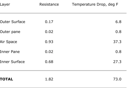
where the resistance is the sum of the resistances of various layers that form the wall. For a double window the total resistance is the sum of five components, viz: outside surface, outer pane, air space, inner pane and inside surface. Values for these resistances can be found in various reference books; one of the most widely used is the Guide and Data Book published by the American Society of heating, Refrigerating and Air Conditioning Engineers (ASHRAE)1This reference gives the over-all conductance for a double window with a ½ inch air space as 0.55 Btu/ft²hr°F, which is the same as 1.82 units of resistance. Table I contains the resistances of the various layers and the temperature drop that occurs across each of them when the outside temperature is 0°F and the inside temperature is 73°F. The heat flow through the window is
q
=
73
= 40 Btu/ft²hr
A 1.82
This simple approach implies that the temperature is uniform over each of the four surfaces; a more detailed analysis of the way the heat is transferred through the window shows that this is only an approximation.
Table I Resistance and Temperature Drops for Elements of a Basic Double Window
Layer Resistance Temperature Drop, deg F
Outer Surface 0.17 6.8 Outer pane 0.02 0.8 Air Space 0.93 37.3 Inner Pane 0.02 0.8 Inner Surface 0.68 27.3 TOTAL 1.82 73.0
The real situation is complicated by the nature of heat flow to the glass surface on the warm side, the transfer of the heat across the air space, and the exchange of the heat between the outer surface and the outside. Resistances to heat flow have been assigned to these elements of the heat flow path in the simple calculation of Table I, and these give reasonably accurate values of the heat flow and temperature when there is no solar radiation falling on the surface. Under some conditions, however, they can lead to erroneous values, and for more accurate results it is necessary to use adjusted values or to adopt a more complicated method of calculation. Some knowledge of the heat transfer processes at surfaces and across air spaces is necessary for an understanding of when this is required. Windows present a particularly difficult case, because over 95 per cent of their resistance to heat flow is provided by surface and air space effects.
Modes of Heat Transfer
Heat energy always tends to migrate in the direction of decreasing temperature. The transfer can be by conduction, convection or radiation. Heat is the energy associated with the perpetual movement of the molecules and temperature is a measure of the vigour of this movement. When materials at different temperatures are in contact the more vigorous molecules transfer
some of their thermal energy to less vigorous ones by collisions. This is the process of heat conduction. It is the only way in which heat can flow through an opaque solid.
Thermal energy can be transported through a fluid by conduction and also by the movement of the fluid from one region to another. This process of heat transfer associated with fluid movement is called convection. When the fluid motion is caused only by buoyancy forces set up by temperature differences the process is referred to as natural or free convection; but if the fluid motion is caused by some other mechanism, such as a fan or pump, it is called forced convection.
All objects continuously lose energy by the emission of electromagnetic radiation and gain energy by absorbing some of the radiation from other objects that is incident on them. This process of heat transfer by radiation can take place without the presence of any material in the space between the radiating objects. These three modes of heat transfer will now be discussed in so far as they influence the temperature and heat flow through the double window considered above.
How Heat is Transferred Through a Window
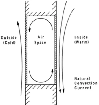
A basic double window is shown in Figure 1. The arrows indicate the direction of the air movement over the window surfaces that occurs when natural convection prevails and the heat flows through the window from inside to outside. There is radiant heat transfer between the inner and outer panes as well as conduction and convection by the air in the space; but the heat flow through the glass itself is only by conduction because glass does not transmit the radiation emitted by objects at normal room temperatures.
Figure 1. Vertical section through basic double window
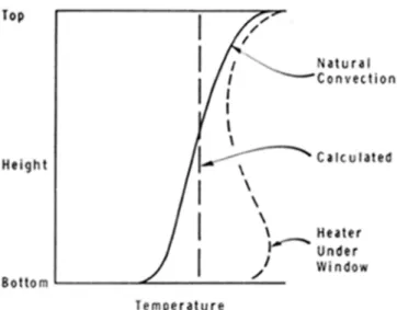
The variation of the inside surface temperature of a basic double window is shown in Figure 2. This variation is due to the air movement on both sides of the inner pane. The warm air of the room first makes contact with the glass at the top of the window, and as it is cooled it moves downwards so that the air in contact with the glass becomes progressively colder as it approaches the bottom of the pane. In the space between the panes the air flows down over the colder outer pane and rises next to the warmer inner pane. Thus the air is moving in opposite directions on the two sides of the inner pane, with the temperature of both streams much lower at the bottom of the window than at the top. As a result, the glass which separates
the two air streams and has a temperature intermediate between them is colder at the bottom than at the top.
Figure 2. Temperature variation over inside pane of basic double window
The cool air from the window continues to settle until it reaches the floor and there it flows horizontally away from the outside wall. This is the commonly-experienced cold draft that chills one's feet when one is near a large window. It can be counteracted by placing a heating outlet beneath a window so that the cold air will mix with warm air from the heater. If the heater discharges warm air onto the bottom of the window it can reverse the direction of the air movement over the lower part of the glass and will greatly increase the minimum temperature of the glass (and heat flow through the window), even though the room temperature remains unchanged. This is shown by the dotted curve in Figure 2.
In addition to convection there is radiation heat transfer occurring at the glass-air interfaces. The rate of energy emission from unit area of a surface, called the emissive power, depends on the temperature and nature of the surface. A "black" surface is one that radiates the maximum possible amount of energy at any temperature. Table II gives the emissive power of a black surface at temperatures the surfaces of buildings are likely to attain.2The ratio of the emissive power of a real surface to the emissive power of the idealized black surface is the emissivity of the real surface.
Table II Emissive Power of a "Black" Surface
Temperature °F Emissive Power Btu/hr ft² Watts/ft² -50 48 14.1 -25 61 17.9 0 76 22.4 25 94 27.7
50 116 33.9 75 140 41.0 100 168 49.2 125 200 58.6 150 237 69.3 175 278 81.4 200 324 95.0
Heat Flow Across an Air Space
Heat is transferred across an air space between two surfaces by radiation and conduction or convection. The conductance by radiation between extensive parallel surfaces is the product of the conductance between black surfaces, hr black, and a factor that depends on the emissivities e1and e2of the two surfaces:
hr= ( e1e2 hr size="1" e1+ e2- e1e2
hr black
The emissivity of glass (and most other non-metallic building materials) is about 0.9, so that the emissivity factor in this expression for hris about 0.82. The value of hr blackcan be found from the data in Table II; for surfaces at 0 and 50°F, for example,
hr black=
(116-76)
= 0.80 Btu/ft²hr°F 50
The value of hrbetween the panes of the double window considered above is, therefore, about 82 per cent of 0.80, i.e. hr=0.66 Btu/ft²hr°F. This indicates that 25 (i.e. 0.66 x 37.3) of the 40 Btu/ft²hr as calculated earlier are transferred across the air space as radiation.
The value of hris practically independent of the thickness of the air space, but does depend on the temperatures of the bounding surfaces. The summer value of hr, can be obtained by assuming the temperatures of the inner and outer panes to be 75°F and 100°F. In this case hrfor glass is 0.92 compared with 0.66 for winter. This is one of the reasons why a warm air space has a lower resistance than a cold one.
The conductance, hc, associated with the conduction-convection heat transfer is dependent on the width of the air space and, to a minor degree, on the average temperature of the air in the space and the total temperature difference across the space. For spaces less than ½ inch thick there is very little convection and hcis equal to the thermal conductivity of the air divided by
the thickness of the air space. The minimum value of hcobtains when the air space thickness is about 5/8 inch; as the thickness is increased beyond this the increase in convection more than compensates for the decrease in conduction. When the air space thickness exceeds 1¼ inches the conductance is practically independent of thickness.CBD 46shows the variation of the overall conductance of a window for air space thicknesses up to 3½ inches.
In an air space enclosed by horizontal surfaces the value of hcdepends on whether the heat flow is upward or downward. For downward flow the warmest air is next to the top surface and the coldest at the bottom, so that there is no tendency for convection currents to be set up and hcfor the space is inversely proportional to thickness, regardless of thickness. When the heat flow is upward through a horizontal air space, convection does occur and the values of the conductance for such a space cannot be calculated simply.
As radiation is the predominant mode of heat transfer when the enclosing surfaces have high values of emissivity, the resistance of an air space can be increased by reducing the emissivity of the enclosing surfaces. Polished metallic surfaces have much lower emissivities than non-metals. Polished silver, for instance has an emissivity of only 0.02 compared with values of 0.90 to 0.95 for most non-metals. The radiative conductance between two parallel, polished silver surfaces is only 1 per cent, and between polished aluminum surfaces 3 per cent, of that between black surfaces at the same temperatures. The foil type of insulation exploits this feature of polished metals. Each layer of foil that is positioned between and parallel to the enclosing surfaces of an air space increases the over-all resistance in two ways: it produces two thinner air spaces, which together have a greater resistance to heat flow by conduction-convection than one thick space; and it reduces the radiative heat transfer very significantly because of the low emissivity of the metal surfaces.
The effectiveness of foil insulation is greatly reduced if condensation occurs on the foil. Even, very thin deposit of water increases the emissivity to a value greater than 0.9. Any holes in or around the foil that allow an interchange of air between the air spaces on the two sides also increase the over-all conductance because of convection between the warm and cold air spaces. It is worth noting that most of the non-reflective insulations achieve their effect by breaking an air space into a multitude of small spaces, thus inhibiting the air circulation that is the basis of convection.
The complications in assigning suitable resistance values to air spaces can now be appreciated more fully. Resistances vary with temperature orientation, thickness of air space, and emissivity of the surfaces involved. Values of the over-all conductance (or resistance) of air spaces can be found in NRC 7788 for the more common situations likely to be encountered in building.
Heat Transfer at an Exterior Surface
The use of a combined surface conductance (hc+ hr) is based on the assumption that heat flow by both radiation and convection is proportional to the same temperature difference. This is valid for an air space, but at a free surface the ambient air temperature can be quite different from the temperature of the objects that are exchanging energy with the surface by radiation. For instance, the outside surface of a wall or window receives a great deal of energy from the sun, and this is quite independent of the temperature difference between the surface and the air. The effects of convection and radiation are combined, in this case by the use of a fictitious temperature called the sol-air temperature (S.A.T.) rather than by a combined surface conductance. The sol-air temperature concept has been discussed inCBD 47, which deals with the extreme temperatures at the outer surfaces of buildings. The heat flow and temperature distribution through a wall or window are calculated as for the simple example above except that the S.A.T. is used instead of the outside air temperature and the surface resistance is l/hc. When there is direct sunshine falling on a wall the S.A.T. can be as much as 100 degrees above the air temperature; and at night when there is a cloudless sky the S.A.T. can be as much as 20 degrees below the ambient air temperature.
As the surface conductance is involved in evaluating and using the S.A.T., it is important that the same value be used in both operations. The choice of the value depends on whether the ambient air temperature will be between the values of S.A.T. and the surface temperature or not. If it is, the heat flows by convection and radiation are in the same direction and the net heat flow is greatest when hcis a maximum. Thus the value corresponding to forced convection with windy conditions should be used. If, on the other hand, the surface temperature is between the S.A.T. and the ambient air temperature (as for most insulated walls when the surface temperature is at a maximum or minimum) the heat fluxes by radiation and convection are in opposite directions. In this case the net flow will be greatest when hcis a minimum. There are very few reliable data on the maximum conductance that can occur at the outer surface of a building. NRC 7788 gives values for the case where the wind is blowing parallel to the surface. When wind Impinges on a surface at an angle the flow pattern over the surface is quite complicated and the conductance can vary considerably from point to point on the building. Projections from the plane of the wall, such as decorative fins or solar shading devices, affect the air flow and thus influence the heat transfer. An outside surface conductance of 6 Btu/ft²hr°F is commonly used for winter design calculations. In the absence of reliable experimental results this value is recommended for those cases where a high value of hcis appropriate. A minimum value of about 1 Btu/hr ft²°F is appropriate for the case with no wind. Heat Transfer at an Interior Surface
The inside surface of a wall or window exchanges heat by convection with the air in the room and by radiation with all the other surfaces that together enclose the room. It is often convenient to allow for the two independent heat transfer processes by using an inside surface conductance that is the sum of hcand hr. just as is done for an air space. This is quite all right so long as the surfaces that can be seen from the wall or window are close to the same temperature as the air in the room. This is usually the case for floors, ceilings and partitions that separate rooms at about the same temperature. It is not true, however, for a corner room, which has two outside walls; nor is it true for a room with a radiant heating system or a high level of artificial lighting. In these cases the radiation and convection can be combined by the use of a fictitious air temperature similar to the sol-air temperature for the outside surface. If the window considered in the first example were part of the outer wall of a room with a radian heating panel in the ceiling, the temperature of the inside surface would be about 4 degrees warmer and the total heat flow through the window would be about 9 per cent greater than that indicated by the simple calculation.
Conclusion
Whenever it is necessary to estimate the average heat flow and temperature at different planes in a wall it should be done by either the graphical or numerical methods described inCBD 36. The data that are required can be found, in almost all cases, in NRC 7788. The results of this calculation must be interpreted, however, with due regard for the approximations that are implicit in this simplified approach.
1. Chapter 23 of the 1963 Guide, which deals with heat transmission coefficients, has been reprinted with permission by the Division of building Research, National Research Council, as NRC 7788.
2. A much more extensive tabulation of the emissive power of a black surface is available as NRC 5947 of the Division of Building Research, National Research Council, Canada.