HAL Id: hal-01074041
https://hal-iogs.archives-ouvertes.fr/hal-01074041
Submitted on 1 Apr 2015
HAL is a multi-disciplinary open access
archive for the deposit and dissemination of
sci-entific research documents, whether they are
pub-lished or not. The documents may come from
teaching and research institutions in France or
abroad, or from public or private research centers.
L’archive ouverte pluridisciplinaire HAL, est
destinée au dépôt et à la diffusion de documents
scientifiques de niveau recherche, publiés ou non,
émanant des établissements d’enseignement et de
recherche français ou étrangers, des laboratoires
publics ou privés.
dual-frequency op-vecsel for cpt-based atomic clocks
(orale)
Paul Dumont, Fabiola Camargo, Jean-Marie Danet, David Holleville,
Stéphane Guerandel, Ghaya Baili, Loïc Morvan, Grégoire Pillet, Daniel Dolfi,
Iryna Gozhyk, et al.
To cite this version:
Paul Dumont, Fabiola Camargo, Jean-Marie Danet, David Holleville, Stéphane Guerandel, et al..
Generation of a high purity microwave signal from a dual-frequency op-vecsel for cpt-based atomic
clocks (orale). International Symposium On Optronics In Defence and Security, Jan 2014, Paris,
France. �hal-01074041�
6th International Symposium On Optronics In Defence and Security
(28-30 January 2014 – Paris)
GENERATION OF A HIGH PURITY MICROWAVE SIGNAL FROM A
DUAL-FREQUENCY OP-VECSEL FOR CPT-BASED ATOMIC CLOCKS
P. Dumont(1*), F. A. Camargo(1), J.-M. Danet(2), D. Holleville(2), S. Guerandel(2), G. Baili(3), L. Morvan(3), G. Pillet(3), D. Dolfi(3), I. Ghozyk(1,4), G. Beaudoin(4), I. Sagnes(4), P. Georges(1), G. Lucas-Leclin(1)
(1) Laboratoire Charles Fabry, Institut d'Optique, CNRS, Univ Paris-Sud 11, Palaiseau, France
(2) LNE-SYRTE, Systèmes de Référence Temps-Espace, Observatoire de Paris, CNRS, UPMC, Paris,
France
(3) Thales Research & Technology, Palaiseau, France
(4) Laboratoire de Photonique et de Nanostructures, CNRS UPR20, Marcoussis, France
* paul.dumont@institutoptique.fr
KEYWORDS: Vertical Cavity Surface-Emitting
Lasers, Atomic Clocks, Metrology.
ABSTRACT
The availability of small atomic clocks should greatly improve the mobility and robustness of, for example, satellite positioning system and high bitrate communication networks. In this context, coherent population trapping (CPT) is an interesting technique for the development of compact atomic references. It is based on the coupling of the two hyperfine ground states of an alkali atom, through excitation to a common atomic level, by two phase-coherent laser fields. We propose an innovating laser source for the production of such bifrequency field based on the dual-frequency and dual-polarization operation of an optically-pumped vertical external-cavity semiconductor laser (OP-VECSEL). Laser noise contributions to clock performance have been evaluated and results in an estimated clock frequency stability of 2.7 x 10⁻¹² over a second limited by laser intensity noise. Stability level below 3 x 10-13 over one second is reasonably reachable with small changes in clock working conditions or laser set-up.
1. INTRODUCTION
Microwave photonics is an emerging field which studies the generation, distribution, processing and analysis of microwave signals carried on optical frequency carriers, using the advantages of photonics technologies [1,2]. It enables access to high-frequency signals generation [3] and processing [4], without the state-of-the-art electronics and also to long range transmission of microwave signals through optical fiber links [5]. Firstly developed for defense applications, microwave photonics spreads to a large number of civil applications such as cellular, wireless, and satellite communications and medical imaging [2]. It is also used in metrology, in the development of frequency standards and inertial captors. Here we are interested in the realization of compact and stable atomic clocks using the coherent population
trapping phenomenon in which the radiofrequency (RF) probe frequency is optically carried [6]. It requires a high purity, optically carried, microwave signal as well as low-noise properties for the laser source (intensity and frequency fluctuations). The common solutions for the generation of an optically carried microwave signal are sideband generation by microwave modulation of a single laser diode, either internally through injection current or externally through an electro-optic modulator [6], and optical phase-locking of two independent single mode lasers [7]. Research on more simple design has also been investigated with development of dual-frequency laser source. As they share the same thermic and mechanic fluctuations, laser modes are intrinsically strongly phase coherent. Dual frequency emission of solid state lasers has been demonstrated with Nd:YAG and Yb:KGW crystals respectively with a frequency difference in the GHz [8] and THz range [3]. A similar configuration has been recently demonstrated with an optically-pumped vertical external cavity surface emitting laser (OP-VECSEL) at 1 µm [9].
We demonstrate here the dual frequency operation of an OP-VECSEL emitting at the Cs D2 line (𝜆 = 852 nm) with a frequency difference tunable to the Cs ground state splitting of 9.2 GHz, and noise properties compatible with population trapping of Cs atoms. OP-VECSEL presents many advantages: first, emission wavelength can be tuned at the desired wavelength thanks to a careful design of the semiconductor structures. Output power in the watt range has been obtained with AlGaAs-based devices. Then, with centimeter long cavity and an excited-carrier lifetime of 1 ns, OP-VECSEL lasers exhibit a class-A dynamical behavior and are therefore relaxation oscillations free. OP-VECSEL relative intensity noise (RIN) is thus very low on a wide spectral range [10]. Finally, single frequency operation of optically-pumped semiconductor lasers with high power has been demonstrated, with narrow spectral linewidth of 100 kHz [11].
The CPT phenomenon and its use in CPT-Ramsey atomic clocks is explained in section II. The next section details the dual-frequency laser design; tunability of the frequency difference between the modes is described. Section IV presents the laser characterization under free-running mode and section V details the stabilization set-up of the laser emission on the Cs three-level system. Finally section VI is dedicated to the measurements of noise properties of the dual-frequency laser, which are then used in section VII to evaluate the laser noise contribution to the clock frequency stability.
2. CPT-RAMSEY ATOMIC CLOCK
Atomic clocks are based on the interrogation of a reference atomic transition by a macroscopic local oscillator (LO) which frequency is locked onto the stable atomic reference, usually in the radiofrequency (RF) range. In CPT-atomic clocks, a 3-level excitation scheme is used, meaning the LO frequency is optically carried using an optical phase-lock-loop to convert the electrical signal to an optical signal [12]. This technology enables the development of miniature atomic clocks with very low level of frequency fluctuations [13]. Such levels of frequency stability in compact housing make possible to integrate atomic clocks in demanding applications as satellite positioning and synchronization of high bit rate communication networks.
CPT phenomenon occurs when two atomic ground states are coupled using a two-frequency coherent laser fields resonant with a common excited state. When the optical frequency difference is equal to the ground state splitting (the so-called clock transition), the atoms are pumped in a coherent superposition of both ground states - called dark state - which does not interact with the incident light (Fig. 1) . At resonance, the light absorption and the fluorescence spectrum exhibit a strong decrease over a narrow spectral linewidth corresponding to the CPT-resonance. This linewidth is related to the coherence lifetime of the ground states. Narrower linewidths can be reached by combining CPT with Ramsey interrogation [6]: it consists, after pumping a group of atoms into the dark state, to let them evolve freely and then excite again those atoms with the resonant 2-frequency optical field. This last pulse induces the Ramsey fringes and is used in the same time for detection by monitoring the fluorescence light or the transmitted power through the atoms. The corresponding signal is used to generate the error signal in order to correct long-term frequency drifts of the local oscillator.
Figure 1. Three-level system of Cs atoms used for CPT. Among alkali-metal atoms used for CPT, cesium atoms have been chosen since 1967 as a frequency etalon to define the second. Its ground state splitting is exactly 9.192 631 770 GHz and it can be either pumped at 894 nm (D1 line) or 852 nm (D2 line) (Fig. 1). CPT-Ramsey atomic clocks using cesium atoms have reached very good frequency stability of 3.2 × 10⁻¹³ at 1 second [14]
limited by LO frequency noise, through Dick effect [15].
3. DESIGN OF THE DUAL-FREQUENCY OP-VECSEL
The optically-pumped VECSEL design has many advantages: it enables the possibility of adding free space intracavity elements while using specially designed semiconductor structure emitting at the targeted wavelength. For this work, we take advantage of our previous work on the design of AlGaAs semiconductor active chips at 852 nm, which have demonstrated up to 300 mW at the Cs D2 line [16].
3.1. Semiconductor structure
The semiconductor chip has been carefully designed to provide light emission at 852 nm and to tolerate optical losses of about 2%, which are introduced by intra-cavity elements (cf 3.2). This conventional multilayer active structure has been grown with metal-organic chemical-vapor deposition on a 350 µm-thick GaAs substrate. The 30λ/4 active cavity is composed of seven 8nm-thick GaAs quantum wells (QW) embedded in pump-absorbing Al0.225Ga0.775As barriers,
absorbing up to 90% of the internal pump intensity in a single pass. QWs are placed at the antinodes of the optical standing wave created inside the active cavity. Two 30-nm thick Al0.39Ga0.61As layers
create potential barriers on each side of the active cavity, for the carrier confinement. Finally, a 50 nm-thick InGaP capping layer protects the cavity from Al-oxidation. The 32.5 pairs of quarter wavelength-thick AlAs/Al0.225Ga0.775As in DBR
provide a 80-nm large high reflectivity pass band centered at 850 nm, with R > 99.94% at 852 nm (Fig. 2) [17].
6th International Symposium On Optronics In Defence and Security
(28-30 January 2014 – Paris)
Figure 2. Multilayer structure index profile with intracavity electric field intensity. Multilayer structure was designed
and fabricated at the Laboratoire de Photoniques et de Nanostructures.
3.2. Laser cavity
The laser cavity is formed by the semiconductor chip and a R = 15 mm concave output coupler, transmitting 0.5 % at 850 nm. The pump source is a broad-area laser diode emitting at 670 nm, coupled into a 100 µm diameter, NA = 0.22, multimode fiber. This source delivers up to 1 W at the fiber end. The pump beam is focused on the semiconductor chip with two doublets of f1 = 25
mm and f2 = 19 mm under a 50° angle, yielding a
70 µm by 110 µm-elliptical spot on the semiconductor structure.
The dual-polarization emission is obtained by introducing a birefringent element in the laser cavity, which controls the anisotropy inside the cavity and results in the emission of two cross-polarized lines (Fig. 3). We use a 500 µm-thick antireflection coated YVO4 plate cut at 45° to its
optic axis, which induces a spatial separation d of 50 µm between the extraordinary and ordinary beams in the structure in the longer axis of the pump ellipse. This spatial separation reduces the coupling between them to C ~ 10%, which ensures a stable dual-polarization frequency emission [18]; nevertheless the spatial separation is small enough to maintain a good overlap between the pump beam and the two laser spots. Finally, the single frequency operation at each polarization, as well as the wavelength coarse tunability, are obtained using a 50 μm-thick (𝐹𝑆𝑅!"#$%& = 2 THz)
uncoated silica etalon. Fine tuning of the laser wavelength is obtained using a piezo transducer glued on the output coupler.
To control the laser frequency difference, a 5 % MgO-doped stoichiometric lithium tantalate (SLT) crystal is placed inside the cavity. Its high transparency at 852 nm limits the intra-cavity losses. Both thermo-optic (T.O.) and electro-optic (E.O.) properties of the MgO:SLT enable a broad tunability of the cavity birefringence. The crystal axes are oriented to limit the ordinary-polarized mode frequency dependency with the SLT applied voltage.
Figure 3. Dual frequency laser cavity.
With all intra-cavity elements, the 𝐹𝑆𝑅 of the laser cavity is 𝐹𝑆𝑅!"# = 12 GHz, higher than the targeted frequency difference ∆𝜈! = 9.192 GHz, and
corresponding to an optical cavity length 𝐿!"# =
12.5 mm.
The laser cavity design has focused on compactness as well as high mechanical and thermal stability (Fig. 4). Pump optics, semiconductor chip and intra-cavity elements are integrated in a compact 90 mm × 90 mm × 40 mm casing. This limits mechanical and acoustic vibrations as well as air temperature fluctuations inside the external cavity. The temperature of the whole set-up is stabilized to 24°C. The semiconductor chip temperature is controlled at 16°C using a Peltier element.
Figure 4. Dual frequency laser prototype. Mechanical design was realized at the Observatoire de Paris.
3.3. Frequency difference tunability
The birefringence introduced in the cavity generates two cavities with slightly different lengths, one per polarization (Fig. 5). Therefore it produces two combs of cross-polarized longitudinal modes, in which only two modes distanced by ∆𝜈 are selected by the Fabry-Perot etalon. For two consecutive modes, the laser beatnote frequency, defined as ∆𝜈 = 𝜈!"#− 𝜈!"# , is given by the
∆𝜈 = 𝐹𝑆𝑅!"# !∆!!
where ∆𝐿 = 𝐿!"#!"#− 𝐿!"#!"# corresponds to the optical
path difference due to birefringence over one round inside the cavity, and is defined modulo 𝜆/2. Thus ∆𝜈 is tunable over one 𝐹𝑆𝑅!"# of the cavity
equal to 12 GHz.
Figure 5. Longitudinal mode selection in the dual-frequency laser.
∆𝐿 is calculated from the contributions of both YVO4 and SLT crystals, taking into account three
main effects: thermal expansion, thermo-optic and electro-optic effects.
∆𝐿!"!! 𝑉, 𝑇 = ∆𝑛!"!! 𝑇 ×𝐿!"!! 𝑇 ∆𝐿!"# 𝑉, 𝑇 = ∆𝑛!"#!.!. 𝑇 + ∆𝑛
!"#!.!.(𝑉) ×𝐿!"#(𝑇)
The birefringence variation of SLT with the applied transverse voltage, follows the relationship:
∆𝑛!"#!.!. 𝑉 = 𝑉 𝑒 𝑛!! 2 𝑟!!− 𝑛!! 2 𝑟!"
where e is the distance between the two electrodes used to apply a voltage 𝑉 on the crystal and equal to 2 mm, 𝑛! and 𝑛! are the refraction
indexes for the extraordinary and ordinary polarizations, 𝑟!! and 𝑟!" are the electro-optic coefficients along the axes x and z, respectively, where x is the axis on which the voltage is applied and z is along the beam propagation.
Temperature variations affect the birefringence in both crystals (YVO4 and SLT) through thickness
dilatation and thermo-optic effects. Contribution of thermal changes on birefringence can be calculated with the following relationship (valid for both crystals): 𝜕(∆𝐿) 𝜕𝑇 = 𝜕𝐿 𝜕𝑇 𝑛!− 𝑛! + 𝐿( 𝜕𝑛! 𝜕𝑇 − 𝜕𝑛! 𝜕𝑇) We introduce the thermal expansion coefficient 𝛼 = !"!"!!, expressed in K-1 and the thermo-optic coefficients 𝛽!, 𝛽! =!"!"!!= ∑𝑎!𝑇! in K-1.
YVO4 material parameters at 25°C Refractive index at 852 nm no = 1.9702 ne = 2.1811 Thermo-optic coefficients (K -1) a0 = -3.67 x 10⁻⁶ a1 = 9.79 x 10⁻⁸ a2 = -1.13 x 10⁻¹⁰ a0 = 8.07 x 10⁻⁷ a1 = 2,89 x 10⁻⁸ Thermal expansion coefficient (K -1) 𝛼!= 2.06 x 10⁻⁶ 𝛼∥= 8.44 x 10⁻⁶
Table 1. Material parameters of YVO4 crystal at 25°C by
Ter-Gabrielyan & al. [19]
MgO-doped SLT material parameters Refractive index at 852 nm no = 2.1441 ne = 2.1418 Thermal expansion coefficient (K -1) 𝛼! = 1.5 x 10⁻⁵ unknown Electro-optic coefficient (pm/V) r13 = 6.96 r33 = 29.6 Thermo-optic coefficients (K -1) a0 = 5.586 × 10⁻⁵ a1 = 0.92168 × 10⁻⁸ a0 = 1.8017 ×10⁻⁵ a1 = 6.1500 ×10⁻⁸
Table 2. Material parameters of SLT crystal doped with MgO at 25°C by Dolev & al. [20].
From those values, we compute the sensitivity of the frequency difference 𝛥𝜈 to temperature and E.O. applied voltage of, respectively, 1.41 GHz/K at 25°C and 1.56 MHz/V. Thus temperature allows a coarse tunability of the frequency difference to the targeted value of 9.192 GHz. Experimentally the sensibility coefficients are 1.4 GHz/K and 1.3 MHz/V, in good agreement with the theoretical values.
4. LASER CHARACTERIZATION
First of all, the laser is characterized without intra-cavity elements. The laser output power reaches 83 mW at 855 nm in a multimode spectrum, and the laser threshold is obtained at 0.25 W of incident pump power (Fig 6). Using the Fabry-Perot etalon with a FSR of 2 THz, the laser operates in single mode emission with a wavelength tunability of almost 5 nm. With all intra-cavity elements, the laser output power decreases to 26 mW at 852.1 nm corresponding to 13 mW per polarization. The laser threshold increases to 0.35 W due to the additional optical losses induced by the cavity elements. The fine tunability of the cross-polarized laser lines is achieved with the rotation of the Fabry-Perot etalon and the adjustment of the cavity length. Proper adjustments of the cavity and pump alignments allows to force the laser emission on two adjacent longitudinal modes on orthogonal polarizations, with a frequency difference ∆𝜈 below the free-(2)
(3)
(4)
(5) (1)
6th International Symposium On Optronics In Defence and Security
(28-30 January 2014 – Paris) spectral range of the cavity.
Figure 6. Laser power characterization for different
cavity configurations. Black: without any intracavity elements. Red: with all intracavity elements, for single
frequency emission at 852.1 nm. Green: with all intracavity elements, for bifrequency emission at 852.1
nm.
The optical spectrum of the dual-frequency laser around 852.1 nm is measured with a Fourier transform optical spectrum analyzer with a resolution of 2 pm (Fig. 7). The beatnote frequency is evidenced by mixing the cross-polarized modes with a polarizer oriented at 45° of their axes, and coupling the beam into a fiber-coupled fast photodiode followed by two low-noise RF amplifiers (Gain = 22 dB each) and a RF amplifier. The generated beatnote frequency is around 9.2 GHz with a spectral linewidth at -3 dB below 600 kHz on a time scale of 300 ms, measured with a resolution bandwidth of 100 kHz (Fig. 9).
Figure 7. Optical spectrum of the dual frequency laser with a resolution of 2 pm. Peaks are separated by 26 pm
corresponding to approximately 9 GHz at 852 nm.
5. LASER STABILIZATION
Under free-running conditions, the laser performance is not compatible with the interrogation of Cs atoms in a CPT-based atomic clock, which requires a high-purity optically-carried microwave signal. For the dual-frequency laser to be actually used on a Cs-atomic clock, the laser emission has to be further stabilized. In this section we detail the stabilization of the ordinary-polarized laser line onto a hyperfine Cs atomic transition,
and the concurrent locking of the frequency difference onto a RF oscillator.
At the output of the laser, the two cross-polarized modes are separated by a polarization beam splitter. The laser is protected from any optical feedback with two -30 dB optical Faraday isolators (one per polarization). A fraction (0.5 mW) of the ordinary-polarized power is injected into a saturated absorption set-up for its stabilization on a Cs atomic transition at 852.1 nm. Finally, both beams are recombined with the same polarization axis in order to measure the beatnote frequency and lock it on the RF frequency reference (Fig. 8).
Figure 8. Stabilization set-up. EO: electro-optic crystal, PZT: piezo-electric transducer, PBS: polarization beam
splitter, BS: beam splitter, AOM: acousto-optic modulator, OSA: optical spectrum analyser, ESA:
electrical spectrum analyzer.
5.1. Optical frequency stabilization at Cs transition
The laser frequency of the ordinary polarized beam is locked onto a Doppler-free transition (F = 4 towards F’ = 4’/5’) of the Cs D2 line using a pump-probe saturated absorption technique [21], as shown in Fig. 8. An acousto-optic crystal is used to modulate the so-called pump beam at 100 kHz to generate an error signal 𝜖!. This method avoids
the direct modulation of the pump diode current, which would simultaneously introduce a modulation of the laser power.
The error signal is integrated and the correction is made by a low-frequency two-integration stages servo loop on the piezo-electric transducer glued to the output coupler. We measured a sensitivity coefficient of the optical frequency to the error signal of 12 MHz/V.
5.2. Frequency difference stabilization
The frequency difference between the two laser modes (the so-called beatnote frequency) is locked onto a local oscillator (LO), which generates a stable RF reference at the frequency 𝜈!", using an
optical phase-lock loop described in this section. After recombining the beams and superimposed their polarization axes, the two laser frequencies are mixed on a fast GaAs photodiode. The subsequent beatnote signal is amplified and mixed with the RF reference to generate an error signal 𝜖! proportional to (Δ𝜈 − 𝜈!"). The error signal is
then amplified by a high-bandwidth proportional-integrator corrector and applied to the intracavity electro-optic crystal to compensate for the frequency-difference fluctuations.
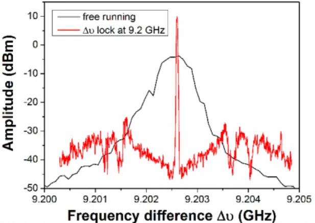
Fig. 9 compares the beatnote spectra of the free-running laser and of the laser when the frequency difference Δ𝜈 is locked to the RF reference at 9.2 GHz. The servo loop bandwidth is about 1 MHz which depends on the proportional gain as well as on the electro-optic crystal response. The signal-to-noise ratio, measured between maximum of the peak and the minimum close the frequency carrier, is 55 dB. The two servo-loops – of the absolute frequency difference on a Cs atomic transition and of the frequency difference on the RF local oscillator – operate together for 30 minutes under laboratory conditions. Better working conditions with acoustic isolation of the set-up is being implemented to achieve a longer operating time for the stabilized laser.
Figure 9. Beatnote frequency spectrum in free-running operation (RBW = 100 kHz) and in lock operation (RBW
= 10 kHz), at 9.2 GHz. Noise is rejected 1 MHz away from the carrier frequency.
6. LASER NOISE AND DYNAMICS
The noise properties of the stabilized laser emission are investigated in order to evaluate the contribution of the dual frequency OP-VECSEL to the performance of a CPT-Ramsey atomic clock. We study three main noise sources: laser frequency noise, beatnote phase noise and laser intensity noise.
6.1. Laser frequency noise
The laser frequency noise reveals the fluctuations of the absolute optical frequency as compared to the Cs transition. It affects the atomic clock by reducing the interaction between Cs atoms and the laser beams. To quantify this frequency noise, we
measure the power spectral density of the error signal 𝜖! with a Fast Fourier Transform analyzer, and normalized it by the sensitivity coefficient of the set-up (12 MHz/V). When the optical frequency locking is activated, we observed a (in-loop) noise level below detection noise floor, meaning we reach a 60 dB frequency noise reduction at 1 Hz. The low-frequency technical noise is suppressed on a bandwidth of 600 Hz, which is limited by the piezo transducer resonance (Fig. 10). In order to have a higher stabilization bandwidth, we investigate establishing an additional feedback loop to the pump injected current.
Figure 10. Power spectrum density of the frequency noise of the ordinary polarized mode, under free-running
operation and under locked operation.
6.2. Beatnote phase noise
The local oscillator (LO) which provides the RF interrogation signal is a key element in an atomic frequency reference. In CPT atomic clocks, the LO frequency is optically carried for the atom interrogation process. Conversion from electrical to optical domain is obtained by locking the laser frequency difference ∆𝜈 to the LO frequency. This conversion may add some noise, originating from the LO oscillator and the laser itself, on the beatnote spectral purity. To characterize the laser additive phase noise (or residual phase noise), we use the set-up presented in Fig. 11 which rejects the LO noise as a common source and measures only the laser additive phase noise.
Figure 11. Additive phase noise measurements set-up. LO: Local oscillator.
6th International Symposium On Optronics In Defence and Security
(28-30 January 2014 – Paris)
Fig. 12 shows the additive phase noise under free running operation and locked operation (for a frequency difference ∆𝜈 locked at the LO reference frequency of 9.6 GHz). A level of -105 dBrad²/Hz on the 100 Hz - 5 kHz frequency range is measured, below the LO standard phase noise, leading to a 100 dB noise reduction of the beatnote phase noise at 100 Hz, compared to the free running operation. At frequencies above 5 kHz, the noise level reaches -90 dBrad²/Hz up to 1 MHz which corresponds to the optical phase-lock loop bandwidth. For higher frequencies a 1/𝑓! slope is
observed which is typical of the behaviour of such lasers under free-running conditions [22].
Figure 12. Power spectrum density of the beatnote phase noise due to the laser contribution under free-running operation and under locked operation (LO frequency: 9.6 GHz) compared to the standard phase
noise of the LO.
6.3. Laser intensity noise
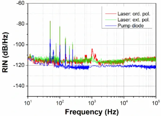
The relative intensity noise (RIN), which is converted into a frequency noise in the phase-lock loop, has been the object of a specific study. A white noise floor of -110 dB/Hz for each polarization has been measured directly at the laser output. Polarization resolved measurements show no difference of the RIN behaviour between the two modes. Moreover, the two frequency-stabilization servo-loops do not disturb the RIN level (Fig. 13).
The laser intensity noise is limited by the pump intensity noise with a gain factor of +5 dB [23]. We have verified that the RIN of the pump diode is not limited by its injected current noise, and we suspect the mode partition noise resulting from the competition between laser modes to be the main limiting factor of the pump source RIN [20]. A lower RIN of our 2-frequency laser should thus be achievable by using a single-mode pump source. High power tapered laser diodes at 670 nm with quasi-single mode emission have been demonstrated [24], and are considered as good candidates.
Figure 13. Spectral density of the laser relative intensity noise for each polarization, and of the pump relative intensity noise. Measurements reveal a gain transfer
factor of +5 dB from pump RIN to laser RIN.
7. EVALUATION OF CLOCK FREQUENCY STABILITY
In this section, we evaluate the laser noise contribution to the atomic clock performance and therefore the ultimate clock frequency stability reachable with a CPT-Ramsey atomic clock using our dual frequency laser source.
The atomic clock set-up is described in Fig. 14. The two cross-polarized laser modes, stabilized on Cs transition lines (852 nm and with a frequency difference of ∆𝜈 = 9.2 GHz), illuminate a cell full of Cs atoms. An acousto-optic modulator is used for temporal pulse shaping. The clock sequence of duration 𝑇! = 6 ms is composed of a first pumping
pulse 𝜏! = 2 ms, a free evolution time 𝑇! = 4 ms
and finally a very short detection pulse 𝜏! = 25 µs, during which the transmitted power through the cell is measured with a photodiode.
Figure 14. General set-up for a CPT-Ramsey atomic clock using Cs atoms trapped in a cell.
The clock frequency 𝜈(𝑡) is defined as the following [21]:
𝜈 𝑡 = 𝜈! 1 + 𝜀 + 𝑦 𝑡
where 𝜈! is the ground-state splitting, 𝜀 the inaccuracy caused by deterministic effects, and 𝑦(𝑡) the frequency stability which corresponds to the relative frequency fluctuations of the clock signal measured on a duration time 𝜏. To characterize the frequency stability of the signal 𝜈(𝑡), Allan variance is commonly used and is defined as:
(6)
𝜎!! 𝜏 =1
2 𝑦!!!− 𝑦! !
where 𝑦! is the average value of 𝑦(𝑡) on a time
interval 𝑡!; 𝑡!!! of duration 𝜏. 𝜎! 𝜏 is given by the
quadratic average of three contributions: the laser intensity noise (IN), the laser frequency noise (FN) and the beatnote phase noise amplified by the Dick effect.
𝜎!! 𝜏 = 𝜎
!/!"! + 𝜎!/!"! + 𝜎!/!"#$!
The major contribution of the laser power fluctuations (IN) is on the amplitude noise of the detected signal 𝑆(𝑡) which is converted into an additional clock frequency noise through the LO lock loop. Since the signal 𝑆(𝑡) is measured during a time 𝜏! = 25 µs, the atomic clock is sensitive to the laser intensity noise on a bandwidth of 1/ 𝜏! =
40 kHz.
The clock frequency is sensitive to the laser frequency fluctuations (FN) during the pumping time 𝜏! of the Cs atoms. A laser frequency variation from the Cs optical transition reduces the interaction between light and atoms. Thus it induces a fluctuation of the number of atoms trapped into the dark-state, converted into amplitude noise on signal 𝑆(𝑡) (Fig. 14). The calculated sensitivity bandwidth is about 700 Hz under usual operating conditions.
Finally, the Dick effect arises from the lack of information on the probe frequency during the pumping of the Cs atoms, equivalent to a dead time during which the LO noise is not probed and then not corrected [15]. It can be described by the down-conversion of the LO frequency noise at Fourier frequencies higher than the interrogation frequency. The LO frequency noise originates from its intrinsic noise and the laser beatnote frequency noise, i.e. the beatnote phase noise evaluated previously. The LO intrinsic noise will not be considered here, as we are only interested here in the noise added by the bifrequency laser source.
Parameter Max Noise Level Allan Variance 𝜎
! 𝜏 Laser intensity noise -110 dB/Hz 2.7 x 10⁻¹² 𝜏!!/! Laser frequency noise 3 x 10⁹ Hz²/Hz (equivalent white noise level) 4.2 x 10 -14 𝜏!!/! Beatnote
phase noise -90 dBrad²/Hz 2,7 x 10
-13 𝜏!!/!
Table 3. Calculations of Allan variance for each laser noise contributions
The Allan variances, calculated for each contribution, are grouped in table 1. White noise assumption is made to simplify calculations. From these calculations, we estimate a clock stability of
𝜎! 𝜏 = 2.7 x 10-‐12 𝜏!!/! , limited by the laser
intensity noise. In order to reach better clock performance, the clock set-up should be adapted. An increase of detection time from 25 µs to 125 µs could reduce the Allan variance to 8.7 x 10⁻¹³ 𝜏!!/!.
However, it may reduce the atomic signal and also decrease the Dick effect [14]. Thus as a second step, a study of the improvements in terms of total signal to noise ratio will be undertaken. The clock sensibility to the laser RIN might also be reduced by monitoring the laser beam power in front of the atomic cell and normalizing the CPT signal. With such a normalization, a three-fold reduction of the contribution of the laser RIN to the Allan variance has been demonstrated for RIN floor level of -110 dB/Hz [25]. Alternatively we may add a power stabilization loop of the pump laser or use a single-mode tapered laser diode as a pump source (cf 6.3).
Once intensity noise contribution will be reduced below the Dick limit, we hope to achieve a total dual-frequency laser contribution to clock frequency stability below 3 x 10-13 𝜏!!/! by a
careful optimization of the beatnote servo-loop gain in order to obtain a flat phase noise level of -105 dBrad²/Hz on the whole 1 MHz bandwidth.
8. CONCLUSION
The dual-frequency emission of an optically-pumped VECSEL has been demonstrated at 852 nm with a frequency difference of 9.2 GHz. Stabilized operation of the laser with both servo-loops activated has been demonstrated. Under this working operation, the laser noise properties have been carefully investigated. Numerical evaluations based on measurements of the frequency noise, the intensity noise and the beatnote phase noise, demonstrate that a clock frequency stability of 2.7 x 10⁻¹² on 1 s may be achieved, limited by the intensity noise contribution. Assuming that we reduce the laser intensity noise contribution by changing either the clock or the laser set-up, the laser contribution to clock frequency stability would be limited by the Dick effect and could be reduced below 3 x 10-13, paving the way for future compact atomic clocks with 1.10-13 frequency stability level.
9. REFERENCES
[1] J. Yao, “A Tutorial on Microwave
Photonics,” IEEE Photonics Soc. Newsl., pp. 4–12, 2012.
[2] D. Marpaung and C. Roeloffzen, “Integrated microwave photonics,” Laser Photon. Rev., pp. 1–30, 2013.
[3] R. Czarny, M. Alouini, C. Larat, M. Krakowski, and D. Dolfi, “THz-dual-frequency Yb3+:KGd(WO4)2 laser for continuous wave THz generation through photomixing,” Electron. Lett., vol. 40, no. 15, pp. 2–4, 2004.
6th International Symposium On Optronics In Defence and Security
(28-30 January 2014 – Paris)
[4] S. Tonda-Goldstein, D. Dolfi, A.
Monsterleet, S. Formont, and J. Chazelas, “Optical signal processing in Radar systems,” IEEE Trans. Microw. Theory
Tech., vol. 54, no. 2, pp. 847–853, Feb.
2006.
[5] F. Narbonneau, M. Lours, S. Bize, A. Clairon, G. Santarelli, O. Lopez, C. Daussy, A. Amy-Klein, and C. Chardonnet, “High resolution frequency standard
dissemination via optical fiber metropolitan network,” Rev. Sci. Instrum., vol. 77, no. 6, 2006.
[6] J. Vanier, “Atomic clocks based on coherent population trapping: a review,”
Appl. Phys. B, vol. 81, no. 4, pp. 421–442,
Jul. 2005.
[7] F. Z. Fan and M. Dagenais, “Optical generation of a mHz-linewidth microwave signal using semiconductor lasers and a discriminator-aided phase-locked loop,”
IEEE Trans. Microw. Theory Tech., vol. 45,
1997.
[8] J. Le Gouët, L. Morvan, M. Alouini, J. Bourderionnet, D. Dolfi, and J.-P. Huignard, “Dual-frequency single-axis laser using a lead lanthanum zirconate tantalate (PLZT) birefringent etalon for millimeter wave generation: beyond the standard limit of tunability.,” Opt. Lett., vol. 32, no. 9, pp. 1090–2, May 2007.
[9] G. Baili, L. Morvan, M. Alouini, D. Dolfi, F. Bretenaker, and I. Sagnes,
“Two-polarization two-frequency operation in a class-A semiconductor laser,” 2009 Int.
Top. Meet. Microw. Photonics, 2009.
[10] G. Baili, M. Alouini, D. Dolfi, F. Bretenaker, I. Sagnes, and A. Garnache, “Shot-noise-limited operation of a monomode high-cavity-finesse semiconductor laser for microwave photonics applications.,” Opt.
Lett., vol. 32, no. 6, pp. 650–652, Mar.
2007.
[11] S. Kaspar, M. Rattunde, T. Töpper, C. Manz, K. Köhler, and J. Wagner, “Semiconductor disk laser at 2.05 µm wavelength with <100 kHz linewidth at 1 W output power,” Appl. Phys. Lett., vol. 100, no. 3, 2012.
[12] A. J. Seeds, “Microwave Photonics,” IEEE
Trans. Microw. Theory Tech., vol. 50, no. 3,
pp. 877–887, Mar. 2002.
[13] S. Knappe, V. Shah, P. D. D. Schwindt, L. Hollberg, J. Kitching, L.-A. Liew, and J. Moreland, “A microfabricated atomic clock,”
Appl. Phys. Lett., vol. 85, no. 9, pp. 1460–
1462, 2004.
[14] J. Danet, M. Lours, S. Guérandel, and E. de Clercq, “Dick effect in a pulsed atomic clock using coherent population trapping (under review process),” IEEE Ultrason.
Ferroelectr. Freq. Control, 2013.
[15] G. J. Dick, “Local oscillator induced instabilities in trapped ion frequency standards,” in Proc. 19th Precise Time and
Time Interval (PPTI) Applications and Planning Meeting, 1987, pp. 133–147.
[16] B. Cocquelin, D. Holleville, G. Lucas-Leclin, I. Sagnes, a. Garnache, M. Myara, and P. Georges, “Tunable single-frequency operation of a diode-pumped vertical external-cavity laser at the cesium D2 line,”
Appl. Phys. B, vol. 95, no. 2, pp. 315–321,
Jan. 2009.
[17] F. A. Camargo, N. Girard, J. M. Danet, G. Baili, L. Morvan, D. Dolfi, D. Holleville, I. Sagnes, P. Georges, S. Guérandel, and G. Lucas-Leclin, “Tunable high-purity
microwave signal generation from a dual- frequency VECSEL at 852 nm,” in
Photonics West 2013, 2013.
[18] V. Pal, P. Trofimoff, B.-X. Miranda, G. Baili, M. Alouini, L. Morvan, D. Dolfi, F. Goldfarb, I. Sagnes, R. Ghosh, and F. Bretenaker, “Measurement of the coupling constant in a two-frequency VECSEL.,” Opt. Express, vol. 18, no. 5, pp. 5008–5014, Mar. 2010. [19] N. Ter-Gabrielyan, V. Fromzel, and M.
Dubinskii, “Linear thermal expansion and thermo-optic coefficients of YVO4 crystals the 80-320 K temperature range,” Opt.
Mater. Express, vol. 2, no. 11, pp. 1624–
1631, Oct. 2012.
[20] I. Dolev, A. Ganany-Padowicz, O. Gayer, A. Arie, J. Mangin, and G. Gadret, “Linear and nonlinear optical properties of
MgO:LiTaO3,” Appl. Phys. B., vol. 96, no. 2–3, pp. 423–432, Apr. 2009.
[21] O. Koslova, “Caractérisation d une horloge à piégeage cohérent de population dans une vapeur thermique de Cs. Principaux effets pouvant affecter la stabilité de fréquence a moyen-long terme,” Université Pierre et Marie Curie, 2012.
[22] S. De, E. A. Amili, I. Fsaifes, G. Pillet, G. Baili, F. Goldfarb, M. Alouini, I. Sagnes, and F. Bretenaker, “Phase Noise of the Radio Frequency (RF) Beatnote Generated by a Dual-Frequency VECSEL,” arXiv Prepr.
arXiv, 2013.
[23] G. Baili, F. Bretenaker, M. Alouini, L. L. Morvan, D. Dolfi, and I. Sagnes,
“Experimental Investigation and Analytical Modeling of Excess Intensity Noise in Semiconductor Class-A Lasers,” J. Light.
Technol., vol. 26, no. 8, pp. 952–961, 2008.
[24] B. Sumpf, P. Adamiec, M. Zorn, H. Wenzel, and G. Erbert, “Nearly diffraction-limited tapered lasers at 675 nm with 1-W output power and conversion efficiens above 30%,” IEEE Photonics Technol. Lett., vol. 23, no. 4, pp. 266–268, Feb. 2011.
[25] J. Danet, O. Koslova, P. Yun, S. Guérandel, and E. de Clercq, “Compact atomic clock prototype based on coherent population
(under review process),” Eur. Phys.