ANALYSIS AND DESIGN OF
STIRLING ENGINES FOR WASTE-HEAT RECOVERY by
RAHMATALLAH SHOURESHI
B.S., Tehran University of Technology (1976)
S.M., Massachusetts Institute of Technology (1978)
SUBMITTED IN PARTIAL FULFILLMENT OF THE REQUIREMENTS FOR THE DEGREE OF
DOCTOR OF PHILOSOPHY at the
MASSACHUSETTS INSTITUTE OF TECHNOLOGY June, 1981
A Signature of Author
Certified by
Department of Mechanical Engineering
IN
Thesis Co-supervisor
111
Thesis Co-supervisorAccepted by
Chairman, Department Committee on Graduate Students
Arcfilven
MASSACHUSETTS INSTITUTE OF TECHNOLOGYOCT 29 1981
uBwPlES -. 0% 'rANALYSIS AND DESIGN OF
STIRLING ENGINES FOR WASTE-HEAT RECOVERY
by
Rahmatallah Shoureshi
Submitted to the Department of Mechanical Engineering on June 8, 1981 in partial fulfillment of the requirement
for the degree of Docotor of Philosophy ABSTRACT
Most of the available waste-heat sources have effective temperatures less than 700 F. In order to utilize these heat sources a low temperature and low temperature-ratio analysis is required to investigate the best alternative for waste-heat recovery among the present existing engines.
A low temperature-ratio preliminary, comparative analysis
of superheated Rankine, non-ideal Stirling, and ideal Brayton engine is presented. This analysis shows the first two have comparable efficiencies at low temperature-ratios and have
superiority over the ideal Brayton engine. Since the Rankine engine has been well investigated for low temperature, and
low temperature-ratio duties,,then a need exists for 'similar analysis on the Stirling engine because its open literature deals largely with high temperature applications.
A new and complete model for a Stirling engine has been
established. This computerized model predicts the behavior of existing engines reasonably accurately for-cases where a
quantitative comparison is available. Moreover, where the information reported is incomplete, the model still offers at least qualitative explanations for the observed effects.
In order to obtain a closed form solution suitable for design optimization a simplified model for practical Stirling engines has been derived. This new model has sufficient accu-racy for prediction of the behavior of real engines and its results are quite close to the complete model predictions.
A general method of Stirling design optimization is
pre-sented. This method, which is based on the simplified model, separately optimizes each component of the engine. Correla-tions are presented to determine optimum geometry for each of the heat-exchangers, based on Mach number, Reynolds number,
operating temperature-ratio, and heat-exchanger dead volume. This optimization method utilizes derived results for optimum swept-volume ratio, phase angle difference between the cylin-der displacements, bore-stroke ratio, and engine speed.
Results of the optimum designed Stirling engine have been compared with available data on Rankine waste-heat en-gines to determine which one performs more efficiently at low temperatures and low temperature-ratios. This comparison
engine operates more efficiently, while for higher temperature ratios a Stirling engine is the better alternative. Also it is
indicated that a low power-level, waste-heat, Rankine engine has vanishing efficiency at temperature-ratio of 1.2 or less;
whereas, an optimized Stirling engine would appear to be capable of operation at temperature-ratios of 1.1 or more.In the latter case, the optimum regenerator has vanishing length, i.e. the Stirling engine has practically no regenerator.
Thesis Supervisors: Professor Henry M. Paynter Professor Joseph L. Smith Jr.,
Thesis Committee Members:
Professor Thomas P. Bligh Professor Borivoje Mikic
iii TABLE OF CONTENTS ABSTRACT LIST OF TABLES LIST OF FIGURES ACKNOWLEGEMENTS MOMENCLATURE CHAPTER I: Page ii vii. ix xii xiv 1.1- Introduction ... 1
1.2- Applications of Stirling Engines Involving Low Temperature Ratios ... 4
1.3- Review of Low Temperature & Low-Temperature-Ratio Efforts ... 7
a)- Rankine Cycle Systems ... 7
b)- Stirling Cycle Systems ... 11
1.4- Objectives and Outline of the Present Study Information Diagram of Thesis ... 13
CHAPTER II: 2.1- Steady State Behavior of Different Engines ... 16
2.1.1- Rankine Engine ... 16
2.1.2- Brayton Engine ... 19
2.1.3- Stirling Engine ... 22
2.1.4- Comparison of Engines ... 24
2.2-Ideal Stirling Engine Analysis ... 25
2.2.1- Ideal Stirling Cycle, Schmidt Equations .... 25
2.2.2- Effect of Imperfect Regenerator and Dead Volume on Ideal Engine ... 30
iv
2.3- Evaluation of Different Types of Losses ... 33
2.3.1- Pressure-Volume Flow Domain Losses ... 34
2.3.2- Temperature-Entropy Domain Losses ... 38
2.3.2.1- Temperature-Drop Losses in Heater and Cooler ... 38
2.3.2.2- Imperfect Heat Transfer in Regenerator4l 2.3.2.3- Axial Conduction Heat Loss ... 42
2.3.2.4- Shuttle Heat Transfer Loss ... 43
2.3.2.5- Heat Leakage ... 44
2.3.2.6- Transient Heat Transfer Loss in the Cylinder ... 46
2.3.2.7- Heat Pumping Loss Inside the Piston and Cylinder Gap ... 52
2.3.3- Force-Displacement Domain Loss ... 52
2.4- Analysis and Modelling of Practical Stirling Engines ... 54
2.4.1- Perfect Engine Model ... 55
2.4.1.1- Solution of System State Equations ... 61
2.4.2- Real Engine Model ... 62
2.5- Results of Complete Model and Comparison with Available Data .. ... 66
2.5.1- Complete Model ... 66
2.5.2- Available Data and Comparison with Complete Model Results ... 68
a)- Philips Engine ... 69
b)- Allison Engine ... 70
CHAPTER III:
3.1- Need for Simplified Stirling Engine Models ... 75
3.1.1- Basic Heat Input and Work Output Derivation76 3.1.2- Derivation of Mass Flow Rates Inside the Stirling Engine ... 80
3.1.3- Losses Calculations by Simplified Model ...86
3.1.3.1- Pressure Drop Losses ... 86
3.1.3.2- Temperature Drop Losses Inside Heat-Exchangers ... 88
3.2- Comparison of Complete and Simplified Models . 90 CHAPTER IV: Procedure and Derivation of Optimization Method for Designing Stirling Engine ... 91
4.1- Optimum Design Model for Stirling Engine ...
93
4.1.1- Regenerator Optimization...98
4.1.2- Cold, Heat-Exchanger Optimization ... 5
4.1.3- Hot Heat-Exchanger Optimization..00000410
4.1.4- Cylinders Optimization ... 112
4.2- Working Fluid for Stirling Engine ... .17
4.3- Derivation of Optimum Speed and Phase Angle(N&<pl1 4.3.2- Optimum Phase Angle ... 124 4.3.1- Optimum Speed ... 4.4- Derivation of Aspect Ratio for the Cylinders
(B/S) ... ...
4.5- Comparison of Optimum Design Model Results with Available Data ...
CHAPTER V:
5.1- Stirling Engine with and without Regenerator 5.2- Low Temperature Rankine Engines ... 5.3- Comparison of Stirling and Rankine Engines
at Low Temperature and Low Temperature-Ratio CHATER VI:
6.1- Significant Contributions of Present Inves-tigation... 6.2- Conclusion ... 6.3- Suggestions for Future Work ... TABLES ... FIGURES . ... REFERENCES ... APPENDICES: . 6
140
-
145
---. 152...
170
... .. - - - - -.-226A- Survey of Stirling Engine Technology ...
B- Stirling Engine for Automative Application
C- Steady State Analysis of Practical Rankine
Engine ... ...
D- Ideal Engine Analysis (Schmidt Solution) ... E- Ideal Engine with Dead Volume ...
F- Stress Analysis for Cylinder Thickness ... G-Calculation of Power Loss Due to Transient Nan-Uniform Temperature Distribution in Cylinders... H- Derivation of State-Equations for Stirling
Engine with Perfect Components... I- Computer Program of Complete Model ...
J- Derivation of Mass Flow Rate in Heat-Exchanger
. 2219
-200
236
-25Z-253
.260
.266
Z74
K- Pressure Losses Derivation by Simplified Model 277
L- Optimization Formulation ... 287
M- Derivation of Optimum Phase Angle & Speed ... 306
N- Optimum Bore/Stroke Ratio ...
316
p- Regenerator Heat Transfer. Area Derivation
...
320
vii LIST OF TABLES
1- Performance of Rankine Engine . ... :152
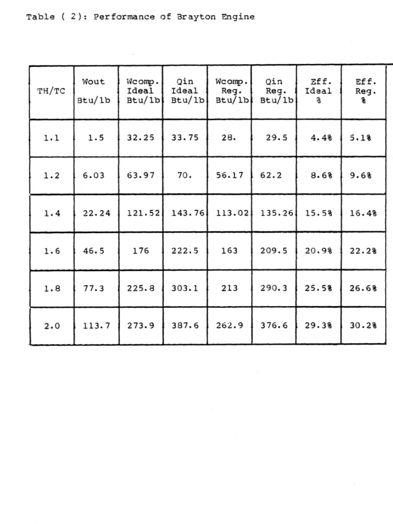
2- Performance of Brayton Engine ... 15!
3- Performance of Stirling Engine ... 154
4- Effect of Regenerator Effectiveness on Stirling
Engine Efficiency ... 155
5- Variation of Stirling Engine Output with Dead
Volume ... 157
6- Comparison of Philips Engine Results and Complete
Model Predictions ...
15$
7- Comparison of Allison Engine Performance with
Complete Model Predictions (4=118) ... 159
8- Comparison of Allison Engine Performance with
Complete Model Predictions ($=112) -... 160
9- Comparison of GPU-3 Performance with Complete Model
Predictions (H2)...
10- Comparison of GPU-3 Performance with Complete Model
Predictions (He2) ... ...162
11- Comparison of Simplified and Complete Model
Predictions ... 12- Optimum Stirling Engine Model Results for Different
Temperature-Ratios (Qin=2000 Watts) ... 164
13A Philips Optimum Design Model Results ... .. 165 13B Philips & G.E Optimum Design Results (Helium as
Working Fluid) ...
165
14- Performance of Stirling Engine without Regenerator(Helium as Working Fluid) ... .
6...
15- Barber-Nichols Model Results for Rankine Engine16- Thermo-Electron Results for Low Temperature-Ratio
Rankine Engine ... ....
67
17- Optimum Stirling Engine Model Results for Different
Temperature-Ratios (Qin=4000 Watts, Helium)....
.16
18- Optimum Model Results for Isothermal Stirling Engineviii LIST OF FIGURES
1- Original Single-Cylinder and Piston Stirling Engine ,170
2- First Double-Acting Cylinders Stirling Engine ... .171 3- Schematic Diagram of OTEC Power Cycle ... 172
4- Cutaway View of TRW OTEC Plant Model ... 173
5- Allied Chemical Corp., 500 KW Sulfuric Acid Waste heat
Recovery, Rankine Cycle ... 174 6- DOE and MTI Binary Rankine Cycle Waste-Heate Recovery 175 7- Variation of Efficiency with Heater Temperature G.M.
Benson, Thermal Oscillators...
176
8- Philips Low Power Level Engine, Computer Results .... '1779- General Electric Stirling-Engine-Powered
Heat-Activated Heat Pump Results ... 178
10- Information Diagram of Thesis ... 15 11- Comparison of Steady State Performance of Real Rankine
and Stirling Engines with Perfect Component and Ideal
Brayton Engine ... ... 1
79
12- Effect of Dead Volume on Stitling Engine Performance
Walker's Results ... 180
13- Effect of Swept-Volume Ratio on Cycle Power Walker's
Results ... .181 14- Effect of Phase Angle ($) on Cycle Power Walker's
Results ... 182
15- Schematic Diagram of a Real Stirling Engine with
Corresponding Bond Graph ... 183 16- Effect of Regenerator Effectiveness on Stirling
Engine Efficiency ...
t84
17- Variation of Stirling Engine Output with Dead Volume 05
18- Schematic Diagram and Energy Flow of Stirling Engine
with Perfect Components and Corresponding Bond Graph 186
19- Bond Graph of a Cylinder ...-...--..--187
20- Energy Flow of a Real Stirling Engine with Different
ix
21- Analysis of a Real Engine, Chapter II ... 189
22- Variation of Mechanical Friction Mean Effective
Pressure (Fmep) with Engine Speed ... 190 23- Thermal Conductivity of Helium and Assigned
Correlation ... 191 24- Thermal Conductivity and Prandlt Number for Hydrogen
and Assigned Correlations ...192
25- Comparison of Philips Engine Output Power with
Complete Model Prediction ... 193 26- Computed Input Heat Versus Measured 'Fuel Mass FloW
Rate-for Philips Engine ....-.----..--..----.--.-.--. 94
27- Comparison of Allison Engine Output Power with
Complete Model Predictions ($=112) ... 195
28- Comparison of Allison Engine Efficiency with
Complete Model Predictions ($=112) ... .196 29- Comparison of Allison Engine Output Power with
Complete Model Predictions ($=118) ... 197
30- Comparison of Allison Engine Efficiency with
Complete Model Predictions ($=118) ...198
31- Comparison of LeRC Model and Complete Model
Predictions for GPU-3 (He) ... 199
32- Comparison of LeRC Model and Complete Model
Predictions for GPU-3 (H2) ... 200
33- Variation of Error between Schmidt and Complete
Model Outputs with Temperature-Ratio , '201
34- Variation of Error between Schmidt and Complete
Model Outputs with Phase Angle ,, ,,,,,,,...202
35- Dead Volume Correction Factor for Schmidt Equation
(TH/TC41.5) ... ... '203
36- Dead Volume Correction Factor for Schmidt Equation (TH/TC)l.5) ... .... ... .. ... 204
37- General Configuration of a Real Stirling Engine 205
38- Temperature Correction Factors for Mass Flow Rates
39- Phase Angle Correction Factors for Mass Rates in
Heater, Cooler, and Regenerator ... 2..07
40- Dead Volume Correction Factor for Mass Flow Rate
in Heater ... 208
41- Dead Volume Correction Factor for Mass Flow Rate
in Cooler Simplified Model ... .209
42- Dead Volume Correction Factor for Mass Flow Rate
in Regenerator ... 210 43- Comparison of Simplified and Complete Models
Predictions ... 211
44- Comparison of Working Fluids by Philips Laboratories 212
45- Comparison of Stirling Engine Output Power with
Different Working Fluids and Different Processes,
Qin=2000 Watt, Pm=500 Psia ... 213
46- Comparison of Stirling Engine Efficiency with Different Working Fluids and Different Processes,
Qin=2000 Watt, pm=500 Psia ... 214
47- Variation of Optimum Speed and Phase Angle with
Temperature-Ratio...215
48- Block Diagram of Synthesis System ... ... ... 216
49- Comparison of Optimum Model Results, Philips Optimum Design Model Results, and Philips & G.E. Experiment,
Hydrogen as Working Fluid ... 217
50- Comparison of Optimum MOdel Results with Philips
and G.E. Experiment .. ' ... 218
51- Comparison of Optimum Designed Stirling Engine
Performance and Thermo-Electron Rankine Engine
Performance
... ... .. . 21952- Comparison of Optimum Designed Stirling Engine
Performance and Barber-Nichols Rankine Engine
Performance ... ... 220
53-
Stirling Engine Power Loss Due to Regenerator PressureDrop ... 221
54- Stirling Engine Heat Loss Due to Regenerator
Imperfection and Axial Conduction ... ... 222
0-55- Variation of Regenerator Optimum Length with
Temperature Ratio ... 223
56- Variation of Net Output Power, Power Losses, and
Heat Losses with Temperature-Ratio ... .224
57- Tension Actuators Acting like a Double-Acting
xii ACKNOWLEDGEMENTS
I am deeply grateful to my thesis supervisors, Professor Henry M. Paynter, a source of never ending knowledge, for his stimulating guidance, patient, and counsel; and Professor
Joseph L. Smith Jr., Whose never-fading enthusiasm helped keep me on the track during the course of this thesis. I sincerely
appreciate them. I would like to appreciate the other thesis committee members, Professors Borivoje Mikic, David Gordon Wilson, and Thomas P. Bligh for their assistance, advices, and guidances throughout and were always willing to serve as soun-ding board for new ideas.
I would like to thank Mr. Francis A. DiBella, Project Engineer at Thermo-Electron Corp., for providing the Rankine engine data which made it possible to have a reasonalble com-parison of the two Stirling and Rankine engines.
I appreciate Dr. Kangpil Lee, senior engineer at Foster-Miller Associates, Inc. for all of his time and effort on clarifying some of the power losses in a Stirling engine.
I am grateful to Helen Doyle for her assistance during the five years of my working with Prof. Paynter.
Most of all, I would like to express my appreciation to my wife, Azar, for her love, encouragement, patient, and supports throughout this thesis.
xiii
NOMENCLATURE
Ac heat transfer area of compression space Ae heat transfer area of expansion space AFRC cooler free flow area
AFRH heater free flow area
AFRR regenerator free flow area
AH heat transfer area B bore of a cylinder
Cp specific heat of working fluid at constant pressure
Cv specific heat of working fluid at constant volume
d diameter of wire or sphere particles in the regenerator
D hydraulic diameter (section 4.1)
normalized dead volume D=(VDR+VDC+VDH)/VC (section 3.1.1)
DC I.D. of cooler tubes (section 4.1.2)
normalized dead volume for cooler VDC/VC (Section 4.1) DH I.D. of heater tubes (section 4.1.3)
normalized dead volume for heater VDH/VC (section 4.1)
DRR
diameter of regenerator cross-sectional areaf average friction factor (section 2.3.1) correction factor (section 3.2)
F Correction factor
Fe enhancement factor for expansion space Fc enhancement factor for compression space
fx friction factor at position x
Fcc mass flow rate correction factor in cooler Fch mass flow rate correction factor in heater
H enthalpy (section 2.2)
coefficient of heat transfer (Appendix L) hi inner coefficient of heat transfer
h outer coefficient of heat transfer
k ratio of constant pressure to constant volume specific heat (Cp/Cv)
Kg thermal conductivity of gas
Km thermal conductivity of material
1 cylinder-piston gap size L length of the component
Lp displacer length
M mass, Mach number
m average mass flow rate
rhx mass flow rate at position x
N engine speed
Nc number of tubes in cooler
NH number of tubes in heater
P pressure
P1 amplitude of pressure variation from its mean value Pr Prandlt number
AP pressure drop Qin input heat
R ideal gas constant (section (2.1.1)) cylinder radius (Appendix G)
Re Reynolds number
S stroke
t thickness
T temperature
TH hot temperature
Tr temperature ratio (TC/TH) TR regenerator mean temperature
AT temperature drop
V volume
VD dead volume
VDC dead volume in cooler VDH dead volume in heater
VDR dead volume in regenerator Vr volume ratio (VC/VH)
X dead volume ratio
Xm amplitude of piston displacement
W work
Wout output work (power) Greek letters:
a aspect-ratio
inverse of Mach number y ratio of Re/M2
6 temperature ratio
dead volume ratio swept volume ratio
W (0t), rotational speed
p density
1- viscousity
phase angle difference between the two cylinder displace-ments.
$p Phase angle difference between pressure wave and expan-sion volume displacement.
t time constant
Subscripts:
am ambient
c compressor, cooler
C cooler, cold
for dead volume
e
expansion space EQ equivalent h heater H Heater, hot in input m mean value min minimum max maximum out output regenerator T for temperatureCHAPTER I
1.1- Introduction
Robert Stirling, a minister of the Church of Scotland and
originator of the regenerative heat exchanger, invented the closed-cycle regenerative engine in 1816, and shortly thereaf-ter a patent on the invention was issued in his name. The eng-gine originally used hot air as a working fluid and was,
there-fore, called a hot-air engine. At the time, this engine satis-fied a demand for a small power plant, since the steam engine had become impractical in the low-power range because of ex-cessive heat losses.
In modern usage, Stirling engine is a device which operat-es on a closed regenerative thermodynamic cycle, with cyclic compression and expansion of the working fluid at different temperature levels, and where the flow is controlled by volume changes, so that there is a net conversion of heat to work.
Engines exist which operate on an open regenerative cycle,
where the flow of working fluid is controlled by valves. For convenience, these may
be
called Ericsoon-cycle machines , but,in practice, the distinction is not widely established and the name Stirling engine is frequently indiscriminately applied to all types of regenerative machine. The generalized definition covers machines capable of operating as prime movers, heat pumps, refrigerating engines, or pressure generators.
Figures (1) and (2) show the original single-/and double-cylinder Stirling engines. Although a number of modifications were made to the original cycle, inadequate understanding of the regeneration process and how practical regenerator design
affec-ted the performance of the cycle prevenaffec-ted the Stirling engine from competing with first the steam engine and later with the internal-combustion engine. Therefore, the hot-air engine, be-cause of inferior efficiency, low mean effective pressure and
low specific power seemed destined for oblivion.
Yet throughout the nineteenth century thousands of hot-air engines were made and used in a wide variety of sizes and shapes in Britain, Europe, U.S.A., and other parts of the world. They were
reliable and reasonably efficient, readily permitting the use of low grade fuels. More importantly, they were safe compared with contemporary reciprocating steam engine installations and their associated boilers, which exploded with depressing regu-larity, due to high working stresses, poor materials and imper-fect joining techniques.
About the middle of the nineteenth century, the invention of the internal-combustion engine, in the form of the gas engine,
and its subsequent development as a gasoline-and oil-fuelled engine, along with the invention of the electric motor, caused the use of Stirling engines to fade rapidly until, by 1914, they were no longer available commercially in any quantity.
In the late 1930s, rebirth of the Stirling engine was start-ed at the Philips Research Laboratories in Holland. Initially
this work was directed to the development of small thermal-power electric generators for radios and similar equipment, for use in remote areas, where storage batteries were not readily available. Studies by Philips and others embraced the experimental
develop-ment of engines of various sizes up to 450 h.p. as is
discus-sed in some detail in Appendix(B).
Over the past several years, interest in the application of Stirling engines to serve a variety of power-producing needs has increased considerably. As it is shown in Appendices(A)and(B), this type of engine have been developed for serving as
thermo-electric generators, motor vehicles, heat pumps in cryogenic
industry, replace for electric motor in air conditioning systems) blood pumps and many other services. Since most of these appli-cations involve with high temperatures and/or high temperature
ratios, consequently in some cases such as automative applica-tions they have ended up with two essential problems: finding materials for high temperature components and sealing problems
due to the high pressure inside the system. Therefore, it has generally been concluded that the Stirling engine is not
presently economical for high temperature applications.
The object of this thesis is an analysis and design of the Stirling engine following a radically different concept from most of the previous attempts. Basic concerns are: low temperatures and low temperature ratios (TH/TC<2), waste heat as the heat source, and low output power level design. As shown in next
sec-tion, there has not been adequate research along these
1.2- Applications of Stirling Engines Involving Low Temperatures
---& Low Temperature Ratios
In the past, major industries have foregone the most effi-cient use of excess process heat and instead purchased supple-mental power and fuel which used to be the lower-cost alterna-tive. Much process heat above 200.F was (and still is) rejected to cooling streams. But as power and fuel costs rise, attitudes are changing. Diminishing world supplies of fossil fuels have
focused attention on the development of more efficient
energy-conversion systems and on the concomitant search for alternative energy sources. Efficient use of all energy resources is becom-ing more important, on both sociological and economic grounds.
One approach to better energy utilization is embodied in the available energy of a given system. For example, in parallel with chemical-processing plants, or for diesel-engine coolants, one might establish a sub-system for converting a fraction of the waste heat to useful power. It is obvious that the tempera-ture ratio (to ambient) of such a waste-heat source is lower than the required temperature ratios for operation of present liquid-fuel engines.
A common and feasible waste-heat source is the exhaust of
any type of internal combustion engine or open cycle gas tur-bine which employs the chemical energy released at high
tempera-ture by fossil fuel combustion. A significant fraction of this
energy is rejected as the sensible heat of the exhaust gases, at
5
heat source for an appropriate thermal engine.
Therefore, it is important to find the most efficient and reliable engine to utilize the available energy of such heat sources. Since air-conditioners and refrigerators are heat pumps working at low temperature ratios, then their reversed cycles might be assumed as alternatives for low-temperature-ratio heat engines. But these cycles can not be simply reversed to generate positive power because the expansion valve must now be replaced
by a pump or compressor, and it is clear that the original
isen-thalpic throttling process is always easier to realize than versed isentropic compression; therefore, in the practical
re-versed cycle there might not be enough expansion work to supply the required compression work. The only cycle in this category
which might have some hope is the Rankine cycle; the following sections (6-1-1) outlines efforts for using this cycle for
waste-heat recovery or for similar use at low temperature ratios. Since the temperature-ratios (to ambient) of most of the available waste-heat sources are substantially less than 2 and the accumulated literature of the Stirling cycle furnishes no
indication of effort at low-temperature-ratio operation, then it would appear to be valuable to perform a complete research
and analysis based on Stirling engines operating at tempera-ture ratios less than 2, thus to determine how close to unity this ratio might become before the engine could no longer gene-rate net output power.
6
engines for low-temperature-ratio applications,and compares the performance of optimized Stirling engines with the perfor-mance of Rankine engines operating under the same conditions.
A significant result is the determination of the
lower-tempera-ture-ratio boundary beyond which no practical engine could gene-rate positive shaft power.
Since waste-heat recovery is a relatively new area, then next section presents a summary of the few low-temperature-ratio efforts which have been done recently.
M--1.3- Review of Low Temperature & Low-Temperature-Ratio Efforts
---The efficiency of both Stirling and Rankine engines increa-ses with increasing heat source temperatures and with decreasing heat sink temperatures. But high temperatures require the use of heat resistant materials, which are relatively expensive. There
are other applications, however, where high efficiencies can be
traded off for lower cost, i.e. where the heat source itself is
at lower temperature, and thus use of conventional or less ex-pensive "hot side" materials is possible. A typical application in the later category is the conversion of solar energy which has the effective temperature (temperature of collected energy
by flat plate or parabolic reflectors) in the 200C to 500C range
There have been some research efforts directed at using a Rankine cycle at a low temperature-ratio, and there are also a few indirect low temperature-ratio research investigations on Stirling engines as outlined below.
a)- Rankine Cycle systems:
Early attempts to use a Rankine cycle for waste-heat re-covery were the initial Ocean Thermal Energy Conversion (OTEC) efforts. OTEC systems involve a process for producing energy
from the difference in temperature between surface and deep sea water and such systems were first promulgated more than 150
years ago. Almost a century ago, the principle was related spe-cifically to the use of sea water as a power source, and full-scale demonstration power plants have been built within the last 50 years [17]. Jacques d*Arsonvalin 1881, suggested
opera-ting a closed system in which a working fluid would be vaporiz-ed by the warm water (30C) of the spring at Grenelle French, then condensed by colder river water (15C), the resulting pressure difference across the system provides a constant source of power. The basic operating principles of OTEC power-plants have remain-ed to this day basically unchangremain-ed since d*Arsonval initially proposed them. -As it is shown in Fig. (3 ) the warm water(25 C)
is pumped through an evaporator containing a working fluid in a closed Rankine-cycle system. The vaporized working fluid then drives a gas turbine which provides the plant power. Then the exhaust fluid is condensed by water drawn up from deep in the ocean. Figure (4 ) shows an OTEC baseline system configuration.
The scale of this figure may be estimated from 24-meter diameter of the evaporator and condenser faces.
The heat exchangers are probably the single most important component of OTEC systems, especially their materials of cons-truction. Choices for material range from titanium at perhaps
$150/m with an indefinitely long life-time to aluminum at $50/nm
bearing perhaps a five-year life and even down to a plastic at $10/m with a completely unknown lifetime. An obvious solution to reducing the exchanger capital cost is to increase the velo-city of either or both working fluids, but this would quickly
increase the parasitic pumping losses, especially on the sea-water side. Another problem is biological fouling of the heat
transfer surface on the sea-water side.
The basic requirements for the ideal working fluid for
OTEC are the pressure-temperature relation of the equilibrium
two-phase mixture, the latent heat of vaporization, the liquid thermal conductivity, chemical stability, low corrosiveness towards the materials of construction, safety, and cost [17). Alternative working fluids are ammonia, propane, isobutane, and
several of the Freons. Most of the studies to date have strongly favored ammonia as the working fluid of choice and indicate a very severe economic disadvantage in using any of the other
candidate fluids.
Eventhough the OTEC environmental work schedule calls for a demonstration of this system by 1981, this now appears to be unrealistic. The important point about OTEC systems is that the absolute temperature ratio is about 1.07, raising the essential question: is it possible to get any net output power given a
1.07 temperature-ratio? During the course of this thesis we will
look at the capabilities of Stirling and Rankine engines
opera-ting at such low-temperature-ratios.
Allied Chemical Corporation and Ishikawajima-Harima Heavy industries Company [12) have jointly pursued the installation and operation of a nominal 500 KW sulfuric acid, waste-heat re-covery, Rankine cycle power plant. Fig. ( 5) shows a schematic
of the cycle showing the waste heat source and the pertinent cycle parameters. The waste heat stream is the sulfuric acid leaving the strong acid absorber tower. The plan is to use a portion of this hot acid for the heat recovery system. The working fluid for the Rankine cycle was chosen to be Genetron
10 133 A, a fluorocarbon with the formula C2H2ClF3.T.he vapor por-tion of the saturapor-tion dome for G133A, in the temperature range from 100 F to 200 F, is essentially parallel to the constant entropy lines which permits very little superheating and no need for an auxiliary regenerative heat exchanger before the
condenser.
Their system is under development regarding its performance. Since their temperature ratio is high enough to overcome the
pre-sent losses, their system is capable of producing net power, but
it may not achieve a practical efficiency.
The Department of Energy (DOE) and Mechanical Technology Incorporated (MTI) have developed a binary Rankine cycle
waste-heat recovery system for diesel generating systems [21]. The
demonstration site is located at a power plant in the village of Rockville center, New York. Fig. ( 6) shows a schematic diagram
of this binary system. The system employs two common fluids, steam and Freon, and is projected to recover 500 KW. The steam topping cycle buffers the Freon bottoming cycle so that the
system can be applied overy a wide range of gas temperatures and not be limited by the stability limits of organic coolants. The temperature-ratio of this system is close to 2; therefore this system is expected to have a reasonable efficiency.
There are other efforts for waste-heat recovery by
apply-ing Rankine cycles. In section (6.2),when the Stirlapply-ing and
Rankine engines are compared, the results and a quantitative summary of those efforts will be discussed.
11 b)- Stirling Cycle Systems:
In spite the fact that there have been numerous develop-ments, employing a Rankine-cycle at low-temperature ratio, there
are only a few research efforts in that area based on the Stir-lirg cycle.
G. M. Benson 5 ] in his research on Thermal Oscillators, which are resonant-free-piston, valveless, closed-cycle
ther-mal machines based on the Stirling and/or Ericson cycles, has explored some low temperature engines. Fig.
(
7 ) shows his re-sults for variation of efficiency as a function of heater tem-perature. This figure indicates that when the hot temperaturegoes below 300 F efficiency would be close to zero or, by con-sidering his cold source temperature, if the temperature-ratio is lower than 1.27 there would be no significant net power.
In 1976 Philips Laboratories started some studies on Stir-ling engine to determine its efficiency as a function of opera-ting temperatures [15]. The engine which has been used is the 1-98 Philips engine. For every combination of temperatures and working fluids and at a number of speeds, the pressure and dimensions were determined such that maximum efficiency was obtained. Fig.
(
3) shows the results of their analysis and ex-periments. These results indicate their minimum temperature-ratio is about 1.27, and in almost all of the cases there is about 5% reduction in efficiency of the engine when the shaft friction is introduced. Although they have concluded that the best working fluid for Stirling engines is hydrogen, yet if we12
look at the results of the low temperature-ratios (TH/TC<2.0) we see there is not that much difference between heliun and
hydrogen results. This follows because flow losses no longer
play a large role and the gas density is no longer so signifi-cant. Finally, at low heater temperatures, the use of a working
fluid with a high density relative to that of hydrogen, results
in low specific power outputs.
There have been, recently, some efforts on using Stirling and Rankine cycles jointly. General Electric has developed a Stirling-engine-powered heat-activated heat pump. This 3-ton
heat pump employs a natural gas-fired Stirling engine to drive the vapor compressor. The concept of a heat-activated heat pump
has the potential of reducing the amount of gas required for space heating. The Stirling engine/Rankine cycle refrigeration
loop concept being developed would consume about one-half the gas required by conventional space heating equipment. Fig. ( 9)
1.4- Objectives and Outline of the Present Study
---Since all of the above confirms that there presently exists no clear analysis of Stirling engines operating at
low-tempera-ture-ratio (close to unity), it is the purpose of this thesis
to present and evaluate an analysis which will be of more gene-ral application to the Stirling engines operating at low tem-perature ratios than are the existing analyses. An information diagram for this study is shown as Fig. (10).
In order to justify the choice of a Stirling engine for waste-heat-recovery applications, Chapter II begins with the comparison of steady state performances of different engines and continues with ideal cycle analyses (i.e, the Schmidt equa-tions) which includes its predictions for optimum design charac-ters. The last part of this chapter is involved with modelling practical Stirling engines, evaluation of different types of
losses and comparison of the complete model with available data. In order for the analysis to be useful for design purposes,
where a large number of alternatives must be compared, it must not require extensive computations. All of the present, prac-tical Stirling cycle models require a good portion of computer time which make them expensive; therefore, Chapter III repre-sents a simplified Stirling engine model and compares its eva-luations with the complete model of Chapter II. Chapter IV deals with the derivation of optimum speed and phase angle difference between the hot and cold spaces. Chapter V shows the special behavior of the engine at low temperatures and low
temperature-14
ratios. Chapter VI compares low-temperature Stirling and
Fic. (10)
INFORMATION DIAGRAM OF THESIS
Looking through the results
of preceding attempts on S.E.
Analysis of
alternative forms of regenerator
4,
Using scaling laws to model
Usi ng scal ing 1aws .to model
this class of engine
Design this class of engine
V
A
Thermofluid analysis required for using
S.E. at low AT and
for. low power-level
units Determination of different alternatives for minimum friction
optimum Optimum Source of Different Optimum
design of desi gn of
Iheatespe-
fluids be- design ofregenerator heat cially usingi havior at - cylinders
CHAPTER II
2.1- Steady State Behavior of Different Engines
Utilization of waste-heat sources require the proper type of engines. Following Martini [13] a first order (steady state)
analysis would be a simple and quick way of comparing different engine performance. Since Rankine, Brayton and Stirling cycles are present possible alternatives, in this section we will eva-lutate and compare the performance of each, at low temperatures and at low-temperature-ratios.
2.1.1- Rankine Engine:
In order to make this comparison closer to reality, the en-gine should be more practical and not taken as the ideal case. As is shown in the following figure, the ideal Rankine cycle, having isentropic expansion and compression, is identical to
Carnot cycle in operation and efficiency. At two states, the
entrance to the pump and at exit from the expander, the flow
TI
H2
17 is a mixture of liquid and vapor and would create some design problems. For example, great difficulties would be encountered
in building a punp that will handle the mixture of liquid and vapor at 1 and deliver saturated liquid at 2. Therefore, this
cycle is not generally practical.
In a practical Rankine engine, the vapor is completely condensed and liquid is delivered to the pump 1-1-2. In order to increase the efficiency and have vapor phase in most parts of expander, vapor is superheated at constant pressure 3-3
In the Carnot engine all the heat transfer is at constant tem-perature, and therefore the vapor is superheated in process
3-3. During this process the pressure is dropping, which means that heat must be tranferred to the vapor as it undergoes an expansion process in which work is done. This also is very dif-ficult to achieve in practice. Therefore the following cycle which has a super heat-reheat process would represent a more practical Rankine engine. Since this engine is used for low temperatures then the expansion and compression processes are assumed isentropic.
5
Fig. (2-2)
For the absolute temperature-ratio ranging from 1.0 to 2.0 with the maximn engine pressure less than 500 psia a proper working fluid would be difluoro-monochloro-ethane (C2H3F2Cl) .
Following states are a sample for calculation of engine
perfor-mance at TH/TC = 1.4 . Appendix ( C ) has these states for
vari-ous temperature ratios.
TC = T = 55 F Td = T3' = 260 F TH/TC=l. 4 State 1: T = 55 F P = 33.23 Psia H = 21.86 Btu/lb S = .0477 Btu/lb R V = 1/71.24 Ft /lb State 2: S = .0477 P = 413.8 H = 22.85 Btu/lb R Psia Btu/lb S S tate 3: P = 413.8 T = 260 F H = 133 S = .22 Ps ia Btu/lb Btu/lb R State 4: P = 120 H = 122.5 S = .22 Ps ia Bt u/lb Btu/lb R
State 5: P = 120 Psia H = 151 Btu/lb S = .264 Btu/lb R State 6: P = 33.23 Psia H = 135 Btu/lb S = .264 Btu/lb R
The intermediate pressure, which is the 120 Psia the pres-sure of reheat process, is calculated by P= P . * P
Thus the overall performance measures bocome:
Wout Wexp - Wcomp. = (H3- H&)+(H5 - Hg)-(Hl- H)=25.51 Btu/lb
Qin = (H3- H2) + (H5- Hq) = 138.65 Btu/lb
Wout
Efficiency = 18.4%
Qin
Table
(
1 ) has the comparable results for Rankine enginesoperating at different temperature-ratios.
2.1.2- Brayton Engine:
The air standard cycle or Brayton cycle is the normal clos-ed cycle model for the gas turbine plant. It consist of two
adiabatic work transfer processes (in ideal case they are
isen-tropic) and two constant pressure heat transfer processes. The
performance of this engine is very sensitive to the compressor
and turbine efficiency. With compressor and turbine efficiencies
of 85%, the maximum power is only 49% of the power which could be obtained with perfect components.
20
T>
WonJ4
Fig. (2-3)10
4
Wnet = Wexp - Wcomp = CP(T - T4) - C,(T2- T,)
Qin = CP (Tj - T) Wnet (T3 - T4 )-(T2- T4 ) T4- T, Efficiency = -- = 1 - - = Qin T3 - T2 T 3 - TZ T1 (T4/T - 1) T (TS /T - 1)
From isentropic expansion and compression:
-IM
> T/ T3 = (Pq /P 3 ) T / T1 = )or Ti/ T3 = T, / T.
Therefore:
Ef f iciency = 1 - T, / T2 = 1 (P2 /Pl 1-k/k
For the following performance calculations the isentropic assumption is used, as it was for Rankine engine. In order to
increase the engine efficiency a regenerative heat exchanger
can be used between compressor and heater.
21
T11
C001.0
ItsG.WT _ _S
Fig. (2-4)
It can be shown that for ideal regenerationG.T4= T, TI= TY) the efficiency is:
Efficiency = 1 -(T / T3)(P 2
)
= 1 - T2/ T3Qin = Cp (T3 - TV) = Cp('t3- Tq) = CT,((T3 / Tj)-(T / T,))
= CpTI (T3 / T, - T3 / T2) = CpT3 (1 - T
/
Tz)WO ut = C,(T3 -T) - Cp(T% - T, ) = CpTI((T3 / T,)-(T / T, + T2/ T + 1)
Helium is used as working fluid, because it has high k = 1.66, and pressure ratio is of order of 2.0. Table ( 2 ) shows the
re-sults for different temperature-ratios.
2.1.3- Stirling Engine:
T1
T H
TC
Win
NOT
cOLD
WC'
TH
2
3
T C
4
TH
T
S
Fig. (2-5)
In the ideal case a Stirling engine consists of two isother-mal expansion and compression processes and two constant volume heating and cooling processes. This ideal cycle might be achiev-ed if there would be no pressure drop in the components of the
engine and if an infinitesimal difference occured between the
two streams in the regenerator. In this case, by applying first
and second law of thermodynamics we obtain the following results
1st Law: QH- QC= Wout
2nd Law: QH/TH - QC/TC = 0
Efficiency = Wout/Qin = 1 - QC/QH = 1- TC/TH
Thus the Stirling engine again achieves the Carnot effi-ciency in this ideal case.
However the piston motion is continuous, not step-wise,
23
As a result, the assumed constant volume heating and cooling processes and instantaneous heat transfer, in isothermal
pro-cesses, are not practical. Therefore, a more practical Stir-ling cycle consists of two adiabatic expansion and compression processes having non-uniform temperature distribution inside the hot and cold spaces. In order to make a more practical
Stirling engine comparable to the practical Rankine one, those losses which seem most important and push the engine farther
from ideal case (Carnot efficiency) must be taken into account. These include heat-transfer losses due to the imperfect
regene-rator, and work losses due to the non-uniform temperature dis-tribution inside the cylinders.
If the regenerator effectiveness is defined as: TR - TC
TH - TC
where TR = (TH - TC)/(ln TH/TC) , then it can be shown that
for isothermal expansion and compression:
L - TC/TH Efficiency =
I + (1-E)(1-TC/TH)/((k-1)*(ln PgL/P ))
It is estimated that the work loss due to the non-uniform temperature distribution is about 20% of the output work, then:
Wout R * (TH-TC) * ln P1 p* 0.80
Qin R * TH * ln P', P1+ Cy* (TH-TR)
24
As is shown in the following sections, hydrogen generally is the most efficient working fluid for Stirling engine. Based on the use of hydrogen, the Stirling engine performance is cal-culated. Table
(
3 ) shows the results.2.1.4- Comparison of Engines:
Comparison of the results of these three engines shows
that Stirling and Rankine engines are more efficient than
Bray-ton engine (efficiency of ideal BrayBray-ton engine is less than the practical Stirling and Rankine engines). Comparison of Stirling
and Rankine engines at low temperature-ratios shows that under
practical conditions comparable Stirling and Rankine engines work almost at the same efficiency level and a more detailed analysis is required to discriminate between them. On the other
hand, at temperature ratios close to unity a Stirling engine
with zero regenerator effectiveness has a comparable efficiency
to both the Rankine and highly regenerative Stirling engines.
Therefore, as is shown in chapter V it would be interesting to determine at low temperature ratios the precise efficiency of
the Stirling engine is with and without a regenerator.
Fig. (11) shows the steady state performances of the above three engines. Since Stirling engine shows a better result, then
it would be one more reason why this thesis has concentrated on Stirling engine for waste-heat recovery.
25
2.2- Ideal Stirling Engine Analysis
---Analysis of the Stirling cycle is complicated by the fact that not all elements of the working fluid pursue the same ther-modynainic cycle. Since the ideal cycle analyses have been sented in closed form solutions, then they are useful for pre-liminary design and first order calculations. In this section the first order analysis (Schmidt equations) are presented and the optimum design characteristics are derived. In Chapter IV the practical optimum results are compared with the optimum
predictions of this section.
2.2.1- Ideal Stirling Cycle, Schmidt Equations:
The ideal Stirling cycle, as discussed in the previous section, consists of two isotherms connected by two isochores. These processes may be produced by interconnecting two
suitab-ly varying volumes through a regenerator. The cycle starts with
isothermal compression in the cold space at cold temperature,TC, process (4-1). Then the gas flows through the regenerator and gains enough heat to reach the hot temperature, TH. This
heat-ing is such that the same volume of gas which enters to the re-generator from cold space should discharge from rere-generator to hot space, i.e. the volume variations of hot and cold spaces
must be appropriately related. This constraint is necessary to satisfy the isochoric heating process (1-2). Then, as gas ex-pands isothermally in hot space (hot cylinder) at TH, requir-ing heat to be added to gas to maintain it at TH, process (2-3).
Then the gas returns through the regenerator where heat is re-moved from the working fluid and stored for its subsequent
return, process (3-4), see Fig. (2-5) of previous section.
As we see, so defined is very idealized and impractical engine. A more realistic cycle and corresponding analysis was devised by Gustav Schmidt in 1871. This analysis which has a sinusoidal volume variation has now become the classical
ana-lysis of the cycle and is generally believed to give a more rea-sonable approximation of actual engine performance. Nevertheless, the analysis still remains very highly idealized, so that in
practice the indicated performance of an engine will likely be no better than 60% of the predicted Schmidt cycle performance.
Principal assumptions of the Schmidt cycle are [25): 1- The regenerative process is perfect.
2- The instantaneous pressure is the same throughout the
system.
3- The working fluid obeys the charcteristic gas equation,
PV = RT.
4- There is no leakage, and the mass of working fluid re-mains constant.
5- The volume variations in the working space occur
sinu-soidally;(this will be used throughout the thesis).
6- There are no temperature gradients in the heat
exchan-gers.
7- The cylinder-wall and piston temperatures are constant. 8- There is perfect mixing of the cylinder contents.
9- The temperature of the working fluid in the dead volumes
is constant.
11- Steady state flow conditions are established.
As it is shown in Appendix ( D ) by applying the above as-surptions and using Vh = 1/2VH(l+COS wt) for volume of
expan-sion space and Vc = 1/2VC[l+COS( W t-
f
)] for volume ofcompres-sion space, followings are resulted:
Instantaneous Pressure = Pmax(l-A)/[l+ACOS ( W-t- G
)]
(D-14)pressure Ratio = Pmax/Pmin = (1+A)/(l-A)
Mean Pressure = Pm = Pmax * (1-A)/(1+A)
Where
X = (Dead Volume) /VH
A
=\f"
/[TC/TIH+VC/VH+4X*TC/(TC+TH)]
B = (TC/TH) +(VC/VH) + 2TC*VC*COSC7/(TH{*VH)
TAN(&) = (VC/VH*SIN C,)/(TC/TH+VC/VH*COSCP)
Since the expansion and compression processes take place
isothermally from the first law the heat transferred 0 is equal to the work done W. As shown in Appendix ( D), followings are resulted.
Expansion Work = IT Pm*VH*A*SIN
61(1+
\Ii7)
(D-21)Compression Work = 1T Pm*VC*A*SIN(C - )/(1+ 1T) (D-22)
Efficiency = (QE-QC)/QE = 1-QC/QE = 1-TC/TH = Carnot Efficiency
Wout =
Tr
*Pm*A*VH*S IN 0 *(1 -TC/TH) / (1+ (D-23)Instantaneous mass: Hot Space:
MH = 1/2VH*Pm*(l-A ) *(l+COSwt)/[R*TH*(l+ACOS(wt- 6 )]
Cold Space:
DEAD SPACE: MD = X*VH*Pm(l-A1 )/[R*TD(l+ACOS( w t- )] Total Mass: VH*Pm(l-A ) MT
CO
TC/TH+2X*TC/(TC+TH)+VC(1+COSq)/(2VH)] R*TC(l+A*COSG)The normalized output power is:
W A Wout/(Pm*VT) = IT/(1+VC/VH)*A*SIN G /(1+ )*(1-TC/TH)
This equation indicates that output power is a function of temperature-ratio (TH/TC), volume ratios (VH/VC,VD/VH), and
phase angle difference between the two spaces (cf).
Appendix
() )
shows the derivation of the optimumparame-ters. To get the optimum dead volume ratio (X VD/VH) the deri-vative results is:
-W 4TTA*Tr*SIN G *Tr* (1-Tr)
%WMMMW =(D-33)
bX (1+Tr) (1+Vr)* ( +:1i+Vl-AT ]*[Tr+Vr+4XTr/ (1+Tr)]
This means that output has a negative slope with respect to X and it decreases continuously by increasing X. Therefore, there is no optimum dead volume ratio and it should be made small as much as possible in practice. Fig. (12) shows the same conclu-sion which Walker [25] has come to by doing significant amount
of calculations.
In order to find the optimum swept-volume (Vr = VC/VH)
based on Schmidt analysis Appendix (D
)
shows that derivative of output respect to Vr yields following quadratic equation:Vr (1-A -A
Vl-A
) -Vr (A +A *Tr+4)J *Tr / (1+T r)+2AVr
*Tr+8P \I-AX*Tr/(1+Tr) -1) (A *Tr+4xT rA /(1+Tr)+Aafl7 *Tr +
29
6
For Tr = .5 , X = 1 , q = 90 ==> Vr = 1.07 For Tr = .25 , X = 1 , q'= 90 ==> Vr = .84
By plotting output versus Vr Walker [25] has come to the same results, Fig.( 1 3) shows his curves.
To get the optimum phase angle difference q, as it shown in Appendix ( D), derivative of normalized output has taken
respect to Cf . The results are summarized in the following
quadratic equation:
Vr *T r[1 /-l/A ]COS g +[Tr +Vr +4X*Tr/ (1+Tr) COS c +
Vr*Tr[1/A -1/ 1-A] = 0
(D-42)
This equation shows how the optimum Cf is related to temper-ature ratio and swept-volume ratio. Walker [ 25] has found the
optimum phase angle difference by plotting the output versus q. Fig. (1-4) shows his results for two different temperature ratios, The above equation would give the same results directly and
quickly.
As the temperature ratio (TH/TC) increases the output would increase and the slope of output power with respect to tempera-ture-ratio is always positive and non-zero.
The result of this section shows the basic equations for design and optimization of Stirling engine for. an ideal case. Chapter IV will show the validity of these results for practical engines.
30
2.2.2- Effect of Imperfect Regenerator and Dead Volume on Ideal Engine:
Practical regenerators are not perfect which means the amount of heat gained by the gas from regenerator material is
less than the heat which was extracted from the gas by the re-generator during the first part of the cycle. Therefore, on the way to the hot space, the gas leaves the regenerator with a temperature less than the hot temperature of the cycle (TH) and
that is the reason for having the heater between regenerator and hot space in real engines. Fig. (15) shows a schematic diag-ram of a real engine, for this engine based on hot and cold tem-peratures we can define a log-mean temperature for the regenera-tor as follows.
TR = (TH-TC)/(ln TH/TC)
Regenerator Effectiveness = E = (TR-TC)/(TH-TC)
> TH - TR = (1-E) (TH-TC)
Qin Cv (TH-TR) + R TH ln Pi/P, = Cv (1-E)(TH-TC)+R TH in P P
Wout R TH In P /P1 - R TC In P, /P1 1 - TC/TH Efficiency = 1+Cv/R*(1-E)(1-TC/TH)/(lnP, /P ) Efficiency (E-16A)
Ideal Eff. l+(l-E)/(k-1)(l-TC/TH)/(lnP3
Fig. (16) and table (4
)
show how the efficiency varies with regenerator effectiveness for different temperature ratios. As the results show, at low temperature ratios (about 1.2) the real engine (i.e, engine with imperfect regenerator) is close to ideal cycle (Carnot efficiency), even at E = 0 the engineefficiency is about 60% of the ideal engine.
Due to the introduction and addition of heater and cooler
to the system and because of imperfect regenerator, there are
some additional dead volumes (void volume) present in the
sys-ten. These dead volumes would push the engine farther fron ideal
case. An inefficient regenerator backed up by an adequate gas
heater and gas cooler will not change the work realized per
cycle but will definitely increase the heat required per cycle.
But addition of dead volume, which must be present in any real
engine, decreases the work available per cycle.
Appendix ( E ) shows the net output of the engine for case
of having dead volume as:
'
t(E-16B)
Where: TR/TH = (1-TC/TH)/(ln TH/TC) ,
TR/TC = (TH/TC-l)/(ln TH/TC)
Fig. (17) and table (5 ) show the variation of output with
increasing dead volume of the system for case A=2 and different
temperature ratios. From the above equation we see if TH/TC gets
large Wout becomes very small. But in the temperature-ratio
range 1.0 to 2.0 the variation of output work with respect to
dead volume is almost independent of temperature-rato.
Although the above calculations regarding the imperfect
re-generator and the presence of dead volume are for steady state
32
real engine trends farther and farther from ideal case. Also they indicate that at low-temperature-ratios dissipation terms and entropy generations are lower.
2.3- Evaluation of Different Types of Losses
Analysis of the Stirling engine is complicated by the fact that not all elements of the working fluid pass through the same thermodynamic cycle. The first order analysis and some of the conventional techniques of considering a fixed mass of wor-king fluid passing through a unique cycle can not be used. It is necessary instead to examine individual volume elements and take into account the movement of working fluid into and out of each one. Since the volume in the heat exchangers (dead volume)
is a significant portion of the total volume in an engine, an important fraction of the working fluid is utilized to pres-surize this space instead of being actually moved from one variable volume to another to contribute effectively to the net output work. In the ideal cycle, where pressurization and depressurization of this volume takes place reversiblly, both effects will cancel out so that no work is required.
However, in a practical engine the hot and cold spaces (cylinders) are nearly adiabatic, and an irreversibility does exist when gas moves from a cylinder into the adjacent heat ex-changer at a temperature different from the heat-exex-changer wall temperature, and this can produce a significant loss.
In general, the losses due to imperfect components can be
divided into three types: those which are in the pressure-volume
flow domain, those in the force-velocity domain, and those which are in the temperature-entropy domain. Pressure drop in the