Carbon Nanotube Growth on Challenging Substrates:
Applications for Carbon-Fiber Composites
by
Stephen Alan Steiner III
B.S., Chemistry Course, University of Wisconsin—Madison (2004)
S.M., Materials Science and Engineering, Massachusetts Institute of Technology (2006) Submitted to the Department of Aeronautics and Astronautics
in partial fulfillment of the requirements for the degree of Doctor of Philosophy
at the
MASSACHUSETTS INSTITUTE OF TECHNOLOGY December 2011
Copyright © 2011 Massachusetts Institute of Technology. All Rights Reserved. Author ...
Department of Aeronautics and Astronautics December 15, 2011 Certified by... Brian L. Wardle Associate Professor of Aeronautics and Astronautics Thesis Supervisor Certified by... A. John Hart Assistant Professor of Mechanical Engineering, University of Michigan at Ann Arbor Certified by... Carl V. Thompson Stavros Salapatas Professor of Materials Science and Engineering Certified by... Michael S. Strano Charles and Hilda Roddey Associate Professor of Chemical Engineering Accepted by... Eytan H. Modiano Professor of Aeronautics and Astronautics
Carbon Nanotube Growth on Challenging Substrates:
Applications for Carbon-Fiber Composites
by
Stephen Alan Steiner III
Submitted to the Department of Aeronautics and Astronautics on December 15, 2011 in partial fulfillment of the
requirements for the degree of Doctor of Philosophy
Abstract
Nanoengineered hierarchal fiber architectures are promising approaches towards improving the inter- and intralaminar mechanical properties (e.g., toughness and strength) and non-mechanical properties of advanced fiber-reinforced composites such as graphite/epoxy. One fiber architecture of particular interest is carbon fiber coated with radially-aligned arrays of carbon nanotubes (CNTs), which can enable through-thickness and interply matrix reinforcement of carbon-fiber-reinforced composites while simultaneously providing additional multifunctional benefits such as electrical and thermal conductivity enhancement. Growth of CNTs on carbon fibers can be achieved by chemical vapor deposition (CVD) techniques, however previous processes for doing so have resulted in a significant reduction in the tensile strength and stiffness of the carbon fibers. This thesis aims to develop an understanding of catalyst-substrate and CVD environment-substrate interactions relevant to maintaining fiber mechanical properties in the growth of CNTs on carbon fibers by CVD and to use this understanding to develop practical approaches for growing CNTs on carbon fibers that simultaneously preserve fiber properties. Novel oxide-based catalysts are demonstrated for the first time to be effective for both CNT growth and graphitization of amorphous carbon and are characterized using in situ metrology. These catalysts show promise for use on substrates that exhibit sensitivity to conventional metal catalysts (such as carbon fibers). New CVD processing techniques based on materials properties unique to this class of catalysts are presented and explored. Coatings for enabling growth of aligned CNTs on carbon fibers, coatings for improving adhesion of materials to carbon fibers, and coatings for facilitating low-temperature growth of CNTs on carbon fibers are developed. The mechanochemical responses of carbon fibers to high-temperature processing, exposure to CVD gases relevant for CNT growth, and in situ tensioning during CVD growth at high temperatures are investigated. Methods for growing CNTs on carbon fibers that enable aligned CNT morphologies and that preserve fiber properties are presented. A new system for optimizing CNT growth on carbon fibers with special considerations for oxide-based catalysts is described. Finally, recommendations for manufacturing hierarchal carbon fibers for composites in an industrially practical way are made.
Thesis Supervisor: Brian L. Wardle
Acknowledgements
Thank you to my family, friends, mentors, and colleagues for everything thus far and everything yet to come, and to the Department of Aeronautics and Astronautics for extending the opportunity to pursue a PhD at MIT to a student with a non-traditional Aero/Astro background.
Table of Contents
1 Introduction 37
1.1 Motivation: Nanoengineered Composite Architectures... 38
1.2 Thesis Outline... 39
2 Background 41 2.1 Overview of Advanced Filamentary Composites ... 41
2.2 Nanoengineered Composite Architectures ... 43
2.3 CNT Growth on Carbon Fibers ... 45
2.4 Challenges Specific to Carbon Fiber as a Substrate... 48
2.5 Unconventional CNT Catalysts... 49
2.6 Conclusions ... 49
3 Objectives and Approach 51 3.1 Objectives... 51
3.2 Approaches to CNT Growth on Carbon Fibers ... 51
3.2.1 Barrier Approaches and Supporting Work ... 53
3.2.2 Direct Approaches and Supporting Work ... 54
3.3 Application of Results... 54
4 Identification of a Non-Metallic Catalyst for Graphitization of Carbon and CNT Growth 55 4.1 Introduction and Overview of the Study... 56
4.1.1 Legacy CNT Catalysts and Their Properties... 56
4.1.2 Summary of Discovery... 58
4.2 Methods... 59
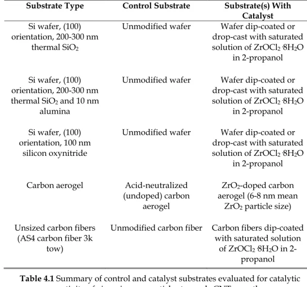
4.2.1 Preparation of ZrO2-Coated Si Substrates ... 59
4.2.2 Preparation of ZrO2-Doped Carbon Aerogels ... 60
4.2.3 ZrO2-Catalyzed Growth of CNTs ... 60
4.2.4 Characterization ... 62
4.3 Results and Discussion ... 64
4.4 Conclusions and Next Steps... 77
5 Understanding Carbon Nanotube Growth from Zirconia 79 5.1 Parameters of Interest for Optimizing CNT Growth With Zirconia ... 81
5.2 Methodology ... 83
5.2.1 Preparation of Zirconia Nanoparticle Catalysts... 83
5.2.2 Preparation of Substrates ... 85
5.2.3 Equipment and Processes for CVD Growth of CNTs... 86
5.2.4 Characterization ... 87
5.2.5 Assessing Results and Promise... 88
5.3 Results of Parametric Study ... 90
5.3.1 Precursor Solution Concentration and Ethylene CVD Temperature... 90
5.3.2 Catalyst Solution Deposition Method and Precursor Solution Concentration... 93
5.3.3 Age of Catalyst Solution and Sonication Prior to Use... 95
5.3.4 Nanoparticle Dispersal Solvent ... 97 5.3.5 Inclusion of Ca2+, Side of Wafer Coated, and Addition of
5.3.6 CVD Process and Support Oxide... 100
5.3.7 Other Zirconia Nanoparticle Sources... 101
5.3.7.1 Micelle Templating with Poly(styrene)-poly(vinyl-4-pyridine) (PS-P4VP) ... 101
5.3.7.2 Dilute Solutions of Zirconium(IV) Acetylacetonate in 2-Propanol ... 102
5.3.7.3 CNT Growth Results... 103
5.3.8 Nanoparticle Pretreatments... 103
5.3.8.1 Oxygen Plasma Pretreatment and Baking in Air to Remove Surface Ligands from Nanoparticles .. 103
5.3.8.2 Hydrogen Plasma Pretreatment to Install Oxygen Deficiency... 106
5.3.8.3 Argon Plasma Pretreatment to Reduce Nanoparticle Size... 108
5.3.9 Parametric Study Conclusions ... 110
5.4 Deductions... 111
5.4.1 Possible “Missing Parameters”: Ultraviolet Radiation, Alkynes ... 112
5.4.2 Preparation of Oxygen-Deficient Zirconia ... 113
5.4.3 Carbon Aerogels as an Alternative to Oxide Supports ... 115
5.4.4 Results... 116
5.4.5 Conclusions and Future Work ... 117
5.5 A Possible Missing Condition: Presence of Solid-State Carbon .... 119
5.6 Conclusions ... 121
6 Development of a CVD System for Carbon Nanotube Growth Optimization 123 6.1 Parameter Space of Interest and Associated Challenges ... 123
6.2 System Overview... 124
6.2.1 Motivation and Design Philosophy... 125
6.2.2 System Concept ... 125
6.2.3 Special Features ... 125
6.2.4 Modular Mass Flow Controller Array Control Box (“MANGO”)... 126
6.2.5 All-Quartz Table-Top Apparatus with Optical Access for Cold-Wall CVD (“TANGO”)... 132
6.2.6 Power Electronics and Feedback Control ... 133
6.3 Implementation... 134
6.3.1 Phase 1: Hot-Wall Configuration and Testing... 137
6.3.2 Phase 2: Cold-Wall Configuration and Integration of Ultraviolet Radiation Source ... 139
6.4 Conclusions and Recommendations... 139
7 Development of Coatings for Facilitating Carbon Nanotube Growth on Carbon Fibers 141 7.1 Functional Coatings for CNT Growth on Carbon Fibers: Objectives and Approaches... 142
7.2 Alumina Barrier Coating Development ... 144
7.2.1 Sol-Gel Deposition of Alumina ... 145
7.2.1.1 Alumina Coatings from Alkoxide-Free Epoxide-Assisted Sol-Gel Processes ... 148
7.2.1.2 Alkoxide-Derived Alumina Coatings... 153
7.2.1.3 Alkoxide-Derived Silica Coatings ... 156
7.2.1.4 Conclusions and Recommendations... 157
7.2.3.1 Solid-Phase Precursor in Hot-Wall Reactor... 167 7.2.3.2 Liquid-Phase Precursor in Hot-Wall Reactor ... 175 7.2.3.3 Liquid-Phase Precursor in Cold-Wall Reactor ... 184 7.2.3.4 Conclusions Regarding CVD of Alumina onto
Carbon Fibers ... 188 7.3 Non-Covalent Functionalization of Carbon Fibers ... 189
7.3.1 Improving Adhesion of Alumina Barrier Coatings with
Poly(styrene-alt-[maleic acid]) (h-PSMA)... 192 7.3.2 Low-Temperature CNT Growth Facilitated by
Poly(styrene-alt-[dipotassium maleate]) (K-PSMA) ... 197 7.3.3 Conclusions, Recommendations, and Future Work
Regarding Non-Covalent Functionalization of Carbon
Fibers with h-PSMA and K-PSMA ... 210 7.4 Conclusions ... 212
8 Mechanochemical Responses of Carbon Fibers to Thermochemical
Processing 215
8.1 Thermochemical Processing of Single Carbon Fiber Filaments .... 216 8.1.1 Preparation and Mounting of Carbon Fiber ... 216 8.1.2 Application of Coatings and CVD Growth of CNTs on
Single Carbon Fibers... 218 8.1.3 Thermochemical Processing of Single Fibers Under
Tension... 219 8.1.4 Single-Fiber Tensile Testing... 224 8.2 Effect of Coatings and CVD Processing on Carbon Fiber Tensile
Properties ... 226 8.3 Mechanochemical Response of Carbon Fibers to Thermal
8.4 Thermochemical Processing of Carbon Fibers Under Tension... 241
8.5 Growth of CNTs on Carbon Fibers Below Strength-Loss Threshold Temperature ... 242
8.6 Conclusions and Future Work... 244
9 Conclusions and Recommendations 247 9.1 Summary of Thesis Contributions ... 248
9.2 Recommendations for Future Work ... 250
9.2.1 Future Work with CNT Growth on Carbon Fibers... 251
9.2.2 Future Work with Oxide Nanopositors... 253
9.3 Conclusions ... 254
Appendix A: Select CVD Process Scripts 257
Appendix B: MANGO Parts List 267
Appendix C: Select Single-Fiber Tensile Test Data 275
List of Figures
2.1 Schematic representation of fuzzy-fiber reinforced plastic architecture.[1,2]... 43 2.2 (Left) Nanostructured carbon fibril-coated carbon fiber prepared
by Downs and Baker, 1995; (right) tensile strength of fibril-coated carbon fibers prepared with low-grade carbon fibers, showing no reduction in tensile strength.[35] ... 47 4.1 (Top) SEM of bundles of aligned CNTs catalyzed by ZrO2 on
silicon oxynitride support using ethylene feedstock at 750°C;
(bottom) close-up of large-diameter MWNTs extending from a
cluster of zirconia particles... 64 4.2 SEM images of CNTs grown from zirconia from ZrOCl2/IPA
solution on a Si wafer with 10 nm alumina support, analyzed by XPS in situ during CVD; (bottom) CNTs grown atop a platelet of zirconia on Si wafer during the in situ XPS analysis ... 67 4.3 Progressive XPS snapshots of the C 1s and Zr 3d regions during
growth of CNTs from zirconia on Si substrate. An appreciable carbon signal only appears upon introduction of both acetylene and hydrogen. No metallic zirconium or zirconium carbide is observed during growth ... 68
4.4 Raman spectrum from carbon nanotubes grown by CVD during
in situ XPS analysis. The presence of radial breathing modes
indicates the presence of single-wall carbon nanotubes... 69 4.5 (Left panel, main image) TEM image of CNTs attached to zirconia
catalyst nanoparticles from in situ XPS growth experiments (Cu with C film TEM grid); (left panel, inset) CNT attached to zirconia catalyst nanoparticle grown from zirconia-doped carbon aerogel;
(right, top) scanning TEM (STEM) image of CNTs extending from
zirconia nanoparticles grown during in situ XPS experiments;
(right, bottom) representative point-localized EDAX spectrum of a
nanoparticle (right, top circled) attached to CNTs from in situ XPS experiment, verifying a particle composition of ~ZrO2... 70
4.6 Powder XRD pattern of ZrO2-doped carbon aerogels with
possible phase matching corresponding to Baddeleyite ZrO2
(gray lines) and an oxygen-deficient phase of zirconia (black lines). The broad peak widths indicate the presence of nanosized crystallites (~7 nm average diameter). No peaks associated with Zr or ZrC are observed. The broad peak centered about 21° 2-θ is associated with the carbon component of the aerogel and is typical of carbon aerogels ... 71 4.7 Representative XPS spectra of ZrO2-doped carbon aerogels
pyrolyzed at 800°C (top row) and 1050°C (middle row) and of undoped carbon aerogels pyrolyzed at 1050°C (bottom row). Two chemistries of Zr are detected in both samples pyrolyzed at 800°C and at 1050°C, both exhibiting binding energies expected for zirconia. No signals attributable to Zr or ZrC (Zr 3d5/2
4.8 Fullerenic cage structures encasing zirconia nanoparticles in ZrO2-doped carbon aerogel pyrolyzed at 800°C. Such structures
are not observed in undoped carbon aerogels ... 74 4.9 (Top) SEM image of multi-wall carbon nanotubes protruding
from the surface of a ZrO2-doped carbon aerogel following CVD.
(Bottom) TEM images of MWNTs emerging from zirconia
nanoparticles embedded in ZrO2-doped carbon aerogel (mass of
circular particles in lower left region); scale bar is 20 nm... 77 5.1 TEM images of 4-nm zirconia nanoparticles used throughout this
study (nanoparticles and images courtesy Jaewon Moon, Hyeon Group, Seoul National University) ... 84 5.2 CNT growth typically found on control wafers upon which no
catalyst or nanopositor nanoparticles have been intentionally added: (left image) typical “debris bundles” found away from edges; (right image) thin- and thick-CNT bundles found at the cleaved edges of the wafer, possibly arising from nanoparticulate silica... 88 5.3 Examples of enhanced CNT growth beyond what is observed on
control samples (grade 1) facilitated by 4-nm zirconia nanoparticles: (left) region containing growth; (right) detail of CNT growth within this region ... 92 5.4 Regions on a wafer covered with 4-nm zirconia nanoparticles
that exhibit CNT growth (marked with ellipses) following CVD processing with 2”-C2H4-680(760) with a grade of 1 ... 92
5.5 SEM images of control wafers (top) and wafers coated with 4-nm zirconia in IPA catalyst solutions deposited by dip-coating
2”-5.6 SEM images comparing influence of drop-casting versus spin-coating on alumina and silica supports for CVD processes C2H2
-750 and CH4-900; CNTs are visible on all drop-cast samples
(more so on SiO2 than Al2O3) and on spin-coated samples with
SiO2 supports processed with CH4-900 ... 96
5.7 SEM of CNTs clusters grown within Marangoni fingers resulting from N2-assisted drying of 4-nm zirconia dispersed in IPA
drop-cast onto a Si wafer with alumina support and processed with 2”-C2H4-680(760); CNTs are present in dark-contrasted regions
outside of the Marangoni pattern as well ... 97 5.8 Optical microscopy of CNT clusters grown within Marangoni
fingers resulting from N2-assisted drying of 4-nm zirconia
dispersed in IPA drop-cast onto a Si wafer with alumina support and processed with 2”-C2H4-680(760)... 98
5.9 Region of CNT growth from sample coated with zirconia deposited from pentane; most of the wafer is bare, however... 99 5.10 SEM images of zirconia nanoparticles from Zr(acac)4/PS-P4VP
showing structures that, at first glance, are similar in appearance to CNTs (top left), however when viewed in a different contrast are found instead to be oxide nanostructures (top right); CNTs resulting from LP-C2H2 (left column, middle and bottom panels) and
CH4-900 (right column, middle and bottom panels) ... 104
5.11 Micro- and nanostructures resulting from CVD processing of wafers coated with solutions of Zr(acac)4 in IPA; little CNT
growth is observed with this approach (grades of 0-0.5)... 105 5.12 Oxide formations observed after CVD processing of wafers
(bottom left), and O2-plasma treatment for 20 min (bottom right); in
some cases webs of oxide nanostructures confusingly similar in appearance to webs of CNTs were observed (such as the structures shown in the bottom right panel) ... 106 5.13 XPS spectra of alumina-supported zirconia nanoparticles before
(gray line) and after (black line) exposure to H2 plasma treatment
showing the emergence of F and N following plasma treatment, likely due to a material incompatibility between parts in the plasma cleaner and H2 plasma... 108
5.14 SEM images of samples processed by Ar sputtering: (top) impact debris and cratering found on control sample; (bottom left) CNTs in good yield over surface of wafers coated with 4-nm zirconia;
(bottom right) similar CNT yield found on control samples,
suggesting the presence of contamination... 110 5.15 Illustration of ultraviolet excitation and engineered feedstocks
enabling CNT growth from an oxide nanopositor, such as a zirconia nanoparticle, on an arbitrary substrate ... 113 5.16 XPS spectra of Zr 3d region of 1-nm zirconia thin film after
sputtering with Ar-ion gun for 30 s, 60 s, 90 s, 120 s, and 150 s; an oxygen-deficient phase is already present after 30 s of sputtering and Zr metal begins to emerge after 90 s ... 114 5.17 SEM images of control sample (CA-10.5) following CVD
processing with 1”-C2H4: (left) overview, (right) detail showing
typical textured surface of a carbon aerogel ... 116 5.18 Growth of CNTs on carbon aerogels loaded with 4-nm zirconia
nanoparticles before pyrolysis (top) and after pyrolysis (bottom) ... 117 5.19 Carbon aerogels loaded with zirconia from saturated
(bottom); samples loaded before pyrolysis result in fields of CNTs
over the sample surface after CVD with 1”-C2H4, whereas
samples loaded after pyrolysis only show a thick, cracked zirconia film ... 118 6.1 CVD system concept featuring dual-manifold gas flow
management system, preheater, and all-quartz-body reactor ... 126 6.2 Two daisychained MANGOs with dual-manifold gas delivery
system connected inline with the preheater module... 129 6.3 Renderings of on-demand-manufactured hinged aluminum
chassis for MANGO ... 129 6.4 Dimensions and positions of standoffs for MANGO chassis
(dimensions are in mm) ... 130 6.5 Dimensions and specifications for relay board lid mounting for
MANGO (dimensions are in mm)... 131 6.6 Circuit board layouts and dimensions for MANGO... 131 6.7 Detail of lid-mounted circuit board hosting data acquisition and
switchboarding (top left) with integrated physical connectors for analog mass flow controllers (top right); detail of panel-mounted LED board and LED/toggle switch driver board (bottom)... 132 6.8 Interior layout of circuit boards, power supply, USB hub, and
power/data entry modules ... 133 6.9 Near-complete MANGO control box: (top left) front of box
showing gas enable switches, gas state LED, and OLED status update screens; (top right) back of box showing welded hinge;
(lower left) power entry module and data entry module (standard
USB type B female); (lower right) data exit and power exit modules for daisychaining ... 134
6.10 Dimensions of TANGO reactor (English units are presented where components are typically sized in English units for convenience) ... 135 6.11 Two-piece all-quartz TANGO reactor with substrate heater
tunnel... 135 6.12 Detail of quartz tunnel for substrate heater in TANGO reactor
bottom: (left) side view of substrate heater tunnel; (right) angled view of substrate heater tunnel showing its penetration through the reactor body ... 136 6.13 TANGO reactor with heat pad installed and operating at ~850°C
(top optical access window remains at ~30°C)... 136 6.14 Power electronics configuration for controlling substrate heater;
a 1.6 kW transformer is shown here for controlling high power-density MoSi2 elements, however a smaller 100 W transformer
may be used for the heat pad... 137 6.15 CNT forests grown with CO2/C2H2 at temperatures ranging
from 700°C to 800°C using the MANGO-TANGO system in hot-wall configuration (i.e., with the preheater serving as the growth reactor)... 138 6.16 CNT forest height versus growth temperature used with
CO2/C2H2 CVD process; the optimal growth condition (factoring
in forest quality) was found to be 760°C ... 138 7.1 Worm- and shell-shaped bundles of aligned CNTs grown
directly on carbon fibers coated with alumina deposited by
sol-gel employing propylene oxide and aluminum(III) chloride ... 152 7.2 Overview of morphology of alumina coating derived from
7.3 Survey of carbon fibers coated with alumina sol prepared by sol-gel employing propylene oxide and aluminum(III) chloride after oxidation at 200°C and subsequent annealing under inert atmosphere at 900°C; film coverage is not extensive and the film readily peels off... 153 7.4 Overview and detail of alumina coating produced by sol-gel
employing baking on ATSB-derived sols, showing extensive cracking and peeling away from the carbon fibers... 155 7.5 Overview and detail of CNT growth on carbon fibers coated
with alumina produced by sol-gel employing baking on ATSB-derived sols showing unaligned growth and non-uniform coverage... 155 7.6 Overview of alumina coating prepared by dip-coating carbon
fibers into sol derived from ATSB/MeOEtOH showing appreciable coverage but severe delamination of the coating off the carbon fibers... 156 7.7 SEM images of sol-gel-derived silica coating on carbon fibers
with sporadic coverage (left), unaligned CNTs grown on a silica deposit on a carbon fiber (right), and representative fibers presenting non-uniform silica/CNT coverage over carbon fibers
(inset)... 157
7.8 Observed and literature values for conductivity of AlCl3-[EMI]Cl
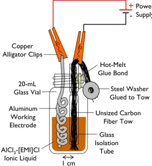
(2:1 molar ratio) ionic liquid as a function of temperature... 161 7.9 Reaction vial for electrodeposition of aluminum onto carbon
fiber ... 162 7.10 Aluminum deposits formed on the aluminum working electrode
7.11 Aluminum deposits on carbon fibers formed by electrodeposition from ionic liquid: (top left) conformally-coated fibers exhibiting some film cracking; (top right) delaminated aluminum film; (lower left) rounded aluminum deposit formed from field lines at fiber tip; (lower right) detail of aluminum grain structure on carbon fiber surface... 167 7.12 Schematic representation of setup used to perform CVD of
alumina from aluminum triisopropoxide ... 169 7.13 Unsized carbon fiber tow and alumina-coated carbon fiber tow
from process Alumina CVD 2, both coated with iron catalyst, before and after CVD growth of CNTs... 171 7.14 (Top left, top right, lower left) SEM images of aligned CNTs grown
on alumina-coated carbon fibers from process Alumina CVD 2;
(lower right) alumina-wrapped carbon fibers after mechanical
delamination of CNTs ... 173 7.15 Carbon fiber weave post-CVD of alumina from ATI exhibiting a
characteristic glossy rainbow glaze indicative of successful deposition... 174 7.16 Schematic representation of setup used for performing CVD of
alumina with aluminum tri-sec-butoxide precursor... 177 7.17 Photograph of CVD setup used for deposition of alumina from
aluminum tri-sec-butoxide in a hot-wall reactor... 177 7.18 (Left) Photographs of desized and alumina-coated carbon fiber
weaves after coating with iron catalyst and subsequent CVD growth of CNTs, where substantial CNT growth is only observed on the alumina-coated sample; (right) photographs comparing the two observed phases of deposited alumina... 183
7.19 Schematic representation of cold-wall reactor designed for CVD of alumina from aluminum tri-sec-butoxide... 184 7.20 Photograph of CVD setup used for deposition of alumina from
aluminum tri-sec-butoxide in a cold-wall reactor ... 186 7.21 (Top) Glossy, rainbow-colored alumina film deposited on
cold-wall reactor sample heater outlining a silhouette of previously processed tows; (bottom left) rings of film thickness variations in alumina coating surrounding tips of cartridges in cold-wall sample heater; (bottom right) alumina-coated steel nut (left) next to uncoated steel nut demonstrating the effectiveness of the alumina CVD process for thermally-conductive materials ... 187 7.22 SEM images of carbon fiber tows after CVD of alumina from
aluminum tri-sec-butoxide onto unsized carbon fibers in a cold-wall reactor revealing a sparse, thin alumina coating with particulate deposits... 189 7.23 Preparation of h-PSMA from PSMA... 194 7.24 FE-SEM and Auger spectra for an unsized, uncoated carbon fiber
(top) and an h-PSMA-coated carbon fiber (bottom); the softer
appearance, reduced charging, and presence of Na on the bottom fiber indicate h-PSMA is present ... 195 7.25 FE-SEM images and Auger spectrum of an alumina coating on a
carbon fiber without h-PSMA underlayer produced with the baked-on alkoxide sol-gel process described in Section 7.2.1.2; substantial film cracking and delamination are observed, resulting in consolidated chunks of alumina rather than uniform coverage... 196 7.26 FE-SEM images and Auger spectrum of an alumina coating on a
on alkoxide sol-gel process described in Section 7.2.1.2; cracking, bare spots, and delamination are substantially reduced (compare to Figure 7.25) and film coverage is consequently improved ... 197 7.27 FE-SEM images and Auger spectrum of a silica coating on a
carbon fiber without h-PSMA underlayer produced with the alkoxide silica sol-gel process described in Section 7.2.1.3; sparse silica coverage is observed in both thin films and
loosely-adhered chunks ... 198 7.28 FE-SEM images and Auger spectrum of a silica coating on a
carbon fiber with h-PSMA underlayer produced with the alkoxide-based silica sol-gel process described in Section 7.2.1.3; silica is present as both a thick coating (top) and conformal thin film (bottom) over the fiber surfaces ... 200 7.29 Comparison of SEM images displaying representative
morphologies for carbon fibers coated with alumina from propylene oxide-assisted gelation without h-PSMA undercoating
(left, post-CNT growth) and with h-PSMA undercoating (right, pre-CNT growth); the presence of h-PSMA expands coverage of the
alumina substantially despite significant (~50%) volume loss due to evaporative drying of the alumina sol-gel deposit ... 201 7.30 Preparation of K-PSMA polyelectrolyte from PSMA... 201 7.31 SEM images of successful growth of CNTs at 480°C on carbon
fibers with K-PSMA coating (anhydride hydrolyzed by NaOH, acid neutralized with K2CO3, 1.5 wt %, doped with catalyst
precursor with Fe3+/IPA) grown via a CO2/C2H2 CVD process:
(top left) representative fiber covered with unaligned CNTs; (top right) overview of fuzzy fibers in tow; (bottom left) detail of a
single fuzzy fiber; (bottom right) infrequent fibers in tow presenting sparser growth... 204 7.32 SEM images of unsized carbon fibers coated with catalyst
precursor by baking on Fe3+/IPA solution and subsequently
CVD processed with CO2/C2H2 at 480°C showing no CNT
growth at any point in the tow: (left) metallic films delaminating from fibers; (right) detail of metallic deposits, revealing a coarse grain structure ... 205 7.33 SEM images of unsized carbon fibers dip-coated with h-PSMA
followed by Fe3+/IPA solution and subsequently CVD processed
with CO2/C2H2 at 480°C showing no CNT growth anywhere in
the tow ... 205 7.34 SEM images of carbon fibers coated with K-PSMA coating
(anhydride hydrolyzed by NaOH, acid neutralized with K2CO3,
1.5 wt %, doped with catalyst precursor with Fe3+/IPA) and
CVD processed with CO2/C2H2 at 480°C (as in Figure 7.31) but
without H2 pretreatment on ramp-up to the temperature set
point, resulting in virtually no CNT growth: (left) unusual crystalline structures lining fibers in the tow; (right) isolated fiber presenting a disordered surface coating ... 206 7.35 Unsized carbon fibers coated with Fe3+/IPA applied onto wet
K-PSMA coating (top left), Fe3+/IPA applied onto wet h-PSMA
coating (top right), Fe3+/IPA applied onto dry K-PSMA coating
(middle left), Fe3+/IPA applied onto dry h-PSMA coating (middle
right), and 0.1 M aqueous Fe(NO3)3 exchanged onto dry K-PSMA
coating (bottom left) followed by CVD processing for CNT growth with CO2/C2H2 at 480°C ... 208
7.36 Results of CNT growth maximization study with Fe3+-loaded
K-PSMA on unsized carbon fibers looking at the effects of Fe3+/IPA solution age (left column), salt used to hydrolyze the
PSMA precursor (middle row), and whether or not K-PSMA forms as a function of pH or from neutralization with K2CO3
(right column middle and bottom)... 209
7.37 SEM images showing the effect of K-PSMA concentration on CNT growth with CO2/C2H2 at 480°C: (left) unsized carbon fiber
dip-coated with 0.5 wt % K-PSMA followed by dip-coating with Fe3+/IPA aged for 30 min showing “knobby” structures over the
fiber surfaces but no CNTs; (right) same as left but dip-coated with Fe3+/IPA aged for 60 min showing very sparse CNT
growth, generally between fibers ... 210 8.1 Graphite frame developed for manipulating and
thermochemically processing single 7-µm-diameter carbon fibers: (top row) dimensions of two-piece graphite frame; (bottom
left) demonstration of top and bottom of graphite frame
illustrating clamping concept; (bottom right) individual Fe3+/alumina/h-PSMA-coated carbon fiber after CVD
processing strung in graphite frame with visible CNT clusters ... 217 8.2 Diagram of all-graphite tensioning frame developed for thermal
processing of single carbon fibers under tension (left) and tungsten-core/graphite-shell high-tension weight for enabling application of higher levels of tension to a fiber than with
all-graphite weights ... 221 8.3 (Left) Dimensions (in mm) for all-graphite tensioning frame;
showing attachment of “horned bumpers” with threaded graphite screws; (lower right) assembled tensioning frame ... 221 8.4 Photographs of all-graphite “horn beetle” tensioning frame:
(upper left) four separate 7-µm-diameter tensioned carbon fibers
supporting dangling tungsten-core weights; (upper right) untensioned tow simultaneously clamped in lower level of frame to provide reference fibers after CVD processing; (lower
left and lower right) tensioning frame positioned in fused quartz
process tube inside electric clamshell furnace ready for CVD processing ... 222 8.5 (Left) Dimensions (in mm) for two-piece graphite weight
assemblies; (middle) exploded view of weight assembly; (right) assembled weight assembly ... 222 8.6 (Left) Dimensions (in mm) for tungsten-core weight assembly
used for higher tension studies and screws used for both weight assemblies and tensioning frame; (right) exploded view of tungsten-core weight assembly ... 223 8.7 Transferring single carbon fiber into the graphite weight
assemblies ... 223 8.8 Transferring the graphite tension frame, loaded with three
tensioned fibers, into the furnace via lab jack... 225 8.9 Aligned (left) and unaligned (right) CNTs grown on an
individual HTR-40 carbon fiber coated with h-PSMA, alumina (from baked-on sol-gel technique described in 7.2.1.2), and Fe3+
with C2H4/H2 at 730°C... 229
8.10 Weibull distributions calculated from single-fiber tensile tests of unsized HTR-40 carbon fibers, h-PSMA-coated HTR-40 carbon
fibers after CVD processing, and Fe3+/alumina/h-PSMA-coated
HTR-40 carbon fibers after CVD processing... 231 8.11 Weibull distributions calculated from single-fiber tensile tests of
unsized HTR-40 carbon fibers after exposure to CVD processing, h-PSMA-coated HTR-40 carbon fibers after CVD processing, and Fe3+/alumina/h-PSMA-coated HTR-40 carbon fibers after CVD
processing; heat treatment, not the presence of coatings, causes the majority (30-35%) of strength loss observed ... 231 8.12 Weibull distributions calculated from single-fiber tensile tests of
unsized HTR-40 carbon fibers thermally processed with and without H2 dwell prior to being heated to 730°C in effort to
quench potential residual oxygen; the H2 dwell approach had no
statistically meaningful effect ... 232 8.13 Weibull distributions calculated from single-fiber tensile tests of
unsized HTR-40 carbon fibers performed to understand potential effects of manipulating carbon fibers individually (e.g., pretensioning) on tensile measurements; the thermal processing of individual fibers results in a slight reduction in measured tensile strength over processing as tows ... 233 8.14 Weibull distributions calculated from single-fiber tensile tests of
unsized HTR-40 carbon fibers as received and after heat treatment in He atmosphere at 480°C, 580°C, and 730°C (heating times indicated refer to length of time that fibers spent at or above 480°C, here 18 min) ... 234 8.15 Losses in mean breaking strength of heat-treated HTR-40 fibers
as a function of temperature and time spent at or above 480°C... 235 8.16 Decrease in mean tensile modulus of HTR-40 carbon fibers as a
8.17 Thermogravimetric analysis of HTR-40 unsized carbon fibers at constant heating rate, showing a thermally-activated process beginning around 550°C; this suggests that these carbon fibers can be thermally processed below 550°C without undergoing mass loss... 236 8.18 Thermogravimetric analysis of unsized HTR-40 carbon fibers in
He atmosphere held at room temperature, 400°C, 500°C, and 650°C showing steady mass loss at 650°C... 237 8.19 Comparison of mean breaking strengths measured for HTR-40
and AS4 carbon fibers after thermal processing in He at various temperatures, verifying strength loss at CVD conditions is not specific to one specific carbon fiber type... 238 8.20 Comparison of mean tensile modulus measured for HTR-40 and
AS4 carbon fibers after thermal processing in He at various temperatures; both show a reduction in modulus at CVD growth temperatures... 238 8.21 Carbon fiber surface nitrogen-to-carbon ratio as measured by
Auger spectroscopy for HTR-40 fibers as received and heat treated in He at 480°C, 580°C, and 730°C... 239 8.22 X-ray diffraction pattern for unsized HTR-40 carbon fibers as
received (light gray trace) and after heat treatment in He at 730°C (dark gray trace); two phases of graphite are superimposed prior to heat treatment, possibly attributable to a bulk fiber core graphite phase and a separate surface graphite phase, which disappears on heat treatment ... 239 8.23 Weibull distributions calculated from single-fiber tensile tests of
applicable level of tension and heat treated in He at a typical CNT growth temperature of 730°C; application of low-level tension enables preservation of tensile strength at temperatures where severe strength degradation is otherwise expected... 243 8.24 Weibull distributions calculated from single-fiber tensile tests of
baseline unsized HTR-40 carbon fibers and HTR-40 fibers coated with Fe3+-loaded K-PSMA coating that were subsequently CVD
processed for CNT growth with CO2/C2H2 at 480°C; no strength
List of Tables
4.1 Summary of control and catalyst substrates evaluated for catalytic activity of zirconia nanoparticles towards CNT growth... 61 4.2 Summary of CVD conditions evaluated for CNT growth from
zirconia catalysts ... 62 5.1 CVD process names and associated CVD conditions used in the
work presented in this chapter ... 87 5.2 Parameter matrix for solution concentration versus CVD
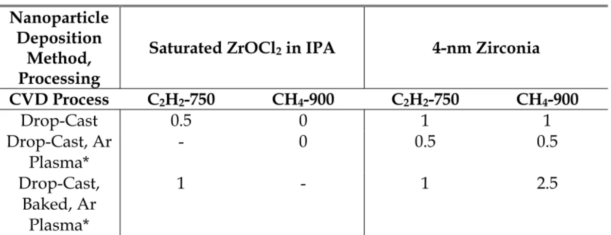
temperature with grades indicating the level of CNT growth observed for each set of conditions... 91 5.3 Parameter matrix for support type and deposition method
versus CVD process with grades indicating the level of CNT growth observed for each set of conditions ... 101 5.4 Parameter matrix for new nanoparticle sources surveyed versus
CVD process with grades indicating the level of CNT growth observed for each set of conditions... 105 5.5 Parameter matrix surveying effects of Ar plasma pretreatment
on two nanoparticle sources versus CVD process with grades indicating the level of CNT growth observed for each set of conditions... 109 5.6 Sample code chart for zirconia-loaded carbon aerogel samples... 116
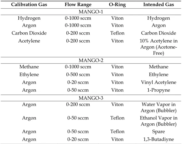
6.1 List of gas calibrations, flow ranges, o-ring type, and intended gases for mass flow controllers on the three MANGOs... 128 7.1 Summary of experimental conditions surveyed for
electrodeposition of aluminum on carbon fiber tows ... 165 7.2 Conditions surveyed for CVD of alumina onto carbon fibers
with ATI ... 172 7.3 Summary of process conditions surveyed for alumina CVD with
ATSB ... 178 7.4 Maps of alumina deposited from ATSB on weaves from each
process ... 179 7.5 Summary of process conditions surveyed for alumina CVD from
aluminum tri-sec-butoxide in a cold-wall reactor ... 190 8.1 Summary of single-fiber tensile test data for carbon fibers as
received, after thermal processing with H2 and subsequent CVD
process suitable for CNT growth, and coated and
CVD-processed... 230 8.2 Summary of single-fiber tensile test data for carbon fibers
thermally processed in He atmosphere as a function of temperature and time... 240 8.3 Summary of single-fiber tensile test data for carbon fibers
thermally processed in He atmosphere under tension as single fibers and control samples processed untensioned as tows... 242 8.4 Summary of single-fiber tensile test data for carbon fibers coated
with Fe3+-loaded K-PSMA CVD processed for CNT growth with
Abbreviations and Symbols
AlCl3 Aluminum chloride
Al(NO3)3 Aluminum nitrate
Al2O3 Alumina (aluminum oxide)
(aq) Aqueous
Ar Argon
AS4 A commercial aerospace-grade high tenacity carbon fiber ATI Aluminum triisopropoxide, Al(OC3H7)3
ATSB Aluminum tri-sec-butoxide, Al(OC4H9)3
C Carbon
C/C Carbon/carbon composite
CF Carbon fiber
CFRP Carbon-fiber reinforced polymer (or plastic)
CH4 Methane
C2H4 Ethylene (ethene)
C2H2 Acetylene (ethyne)
CO Carbon monoxide
CO2 Carbon dioxide
CO2/C2H2 Chemical vapor deposition with carbon dioxide and acetylene
CNT Carbon nanotube
CVD Chemical vapor deposition
DAQ Data acquisition device
E Tensile modulus
EDAX Energy-dispersive X-ray spectroscopy
eV Electron volt
[EMI]Cl 1-ethyl-3-methylimidazolium chloride Fe(NO3)3 Iron(III) nitrate
Fe(NO3)3/IPA Solution of 0.050 M iron(III) nitrate nonahydrate in 2-propanol
FE-SEM Field emission scanning electron microscopy FFRP Fuzzy-fiber reinforced polymer (or plastic) GPa Gigapascals, 109 kg s-2 m-1 = 109 N m-2
HCl Hydrochloric acid
HCN Hydrogen cyanide
He Helium
H2O Water
h-PSMA Poly(styrene-alt-[maleic acid]) HR- High-resolution-
HTR-40 TohoTenax high tenacity research-grade carbon fiber
ID Inner diameter
IEC International Electrotechnical Commission standard
IPA 2-propanol (isopropanol)
IR Infrared keV Kiloelectron volts, 103 eV
K-PSMA Poly(styrene-alt-[dipotassium maleate]) LP-CVD Low-pressure chemical vapor deposition
MANGO Modular mass flow controller array in new CVD system MeOEtOH 2-methoxyethanol
MFC Mass flow controller
MoSi2 Molybdenum disilicide
MPa Megapascals, 106 kg s-2 m-1 = 106 N m-2
MWNT Multiwall carbon nanotube N Nitrogen
NaF Sodium fluoride
NaOH Sodium hydroxide
nm Nanometer, 10-9 m
OD Outer diameter
OLED Organic light-emitting diode PAN Poly(acrylonitrile)
PSMA Poly(styrene-alt-[maleicanhydride])
RF Resorcinol-formaldehyde polymer
RTMS Real-time multiple strip (an X-ray detection technology)
S(x) Standard deviation
sccm Standard cubic centimeters per minute = cm3 min-1 = mL min-1
SCR Silicon-controlled rectifier SEM Scanning electron microscopy
sFEG Schottky field emission gun SiO2 Silica (silicon oxide)
SSR Solid-state relay
SWNT Single-wall carbon nanotube t Time
TANGO Table-top all-quartz reactor in new CVD system TEM Transmission electron microscopy
Ta2O5 Tantala (tantalum oxide)
TGA Thermogravimetric analysis
TiO2 Titania (titanium oxide)
USB Universal serial bus UV Ultraviolet VAC Volts alternating current VDC Volts direct current
XRD X-ray diffraction
XPS X-ray photoelectron spectroscopy Zr Zirconium
Zr(acac)4 Zirconium acetylacetonate, Zr(C5H7O2)4
ZrC Zirconium carbide
ZrO2 Zirconia (zirconium oxide)
ZrOCl2 Zirconium oxychloride, usually as ZrOCl2·8H2O
α Weibull modulus
β Weibull location parameter (set equal to mean breaking strength)
µm Micron (or micrometer), 10-6 m
Ξ Applied tension
Ξ Maximum tension that can be practically applied σ Tensile strength, fiber breaking strength
Chapter 1
Introduction
Lightweight structural materials are of great technological importance in many industries. The ability to minimize the weight of a structure while simultaneously maintaining suitable strength, stiffness, resistance to fracture, and tolerance to damage for the structure to serve its function benefits many applications where weight and cost are coupled. In aircraft and spacecraft, for example, reduced structural weight translates into improved fuel efficiency and expanded payload capacity, in turn reducing operational costs. Similarly, lightweight structural materials reduce operating costs and reduce fuel consumption in the automotive and marine industries by reducing the fuel needed to transport people and cargo. Numerous other markets, for example, wind energy turbines, also see demand for improved lightweight structural materials.
Over time, the availability of lightweight structural materials has expanded from naturally available materials such as wood, canvas, and cotton fibers to crude metals and basic alloys; engineered materials such as synthetic polymers, advanced alloys, and ceramics; and now engineered material architectures such as fibers, foams, thin films, nanoparticles, patterned arrays, and more. Today, advanced materials are engineered through processing techniques that arrange matter into specific configurations at length scales ranging from molecular to macro, often combining multiple substances together to achieve the desired properties in the resulting bulk material. Where in the past a single “default” or “best compromise” material may have been used to make multiple structural elements throughout a vehicle or structure, today specialized, engineered materials can be created to optimally perform the exact physical role demanded by specific points within a structural element. For example, the bending stiffness of a heavy steel I-beam can be achieved at a fraction of the weight by employing a sandwich
structure of graphite/epoxy laminates with a polymeric foam or aluminum honeycomb core. In this configuration, materials optimized for the stress profile experienced at their respective locations in the beam are used—high tensile strength graphite/epoxy to transmit the relatively high normal stresses encountered at the top and bottom of the beam, and rigid foam or honeycomb to transmit the relatively high shear stresses experienced in the middle of the beam.
1.1.
Motivation: Nanoengineered Composite
Architectures
This thesis is motivated by the already-underway evolution of composite materials, critical to future aerospace and environmental needs, into sophisticated, multifunctional architectures that are engineered not only at macroscopic and microscopic length scales, but also at nanoscopic length scales—the fundamental limit of materials engineering. Nanoengineering offers the promise of being able to address shortcomings that have limited the utility of composites for many applications and to install new, active functionalities into materials that will enable new applications and better performance in critical metrics.
Nanoengineered hierarchal fiber architectures are a promising approach towards improving the fracture toughness, inter- and intralaminar strength, and non-mechanical properties of advanced fiber composites such as graphite/epoxy. One fiber architecture of particular interest is carbon fiber circumferentially coated with arrays of aligned carbon nanotubes (CNTs), which could in principle enable through-thickness and interply matrix reinforcement of carbon fiber reinforced composites with multifunctional additional benefits such as providing electrical and thermal conductivity enhancement. Indeed, previous studies investigating the use of alumina fibers coated with CNT arrays for laminated composites have verified this target fiber architecture to be effective in improving the mechanical, electrical, and thermal properties in alumina fiber reinforced composites.[1-4] Growth of CNTs on carbon fibers, however, has proven to be less straightforward than on alumina fibers, as applying analogous CNT growth methodologies to carbon fibers results in significant degradation of tensile strength and stiffness of carbon fibers and, subsequently, may negatively impact fiber-dominated in-plane properties of composites prepared with such fibers. As such, a methodology for growing CNTs on carbon fibers in a way that does not reduce the tensile strength and stiffness properties of the carbon fibers must be developed. Underlying this technical challenge is a need for better
growth and the substrate supporting the catalyst, as well as the response of carbon fibers to the chemical vapor deposition (CVD) growth environment commonly used to grow CNTs.
1.2.
Thesis Outline
In this thesis, catalyst-substrate and CVD environment-substrate interactions relevant to CVD growth of CNTs on carbon fibers are explored. These understandings are then used to inform practical approaches for growing CNTs on carbon fibers that simultaneously preserve fiber properties and to challenge previously conceived notions regarding mechanisms underlying CNT growth.
In Chapter 2, an overview of composites and their shortcomings is presented, followed by a discussion of nanoengineered composites as a promising approach towards addressing these shortcomings. Reasons why growth of CNTs on carbon fibers remains an important outstanding challenge in the field of nanoengineered composites are discussed and a review of efforts in this area is presented. Difficulties underlying CNT growth on carbon fibers from a materials chemistry perspective are then discussed.
In Chapter 3, the objectives of this thesis are articulated and the methodology employed for understanding and engineering CNT growth on carbon fibers is described.
In Chapter 4, for the first time, an oxide-based material, zirconia, is demonstrated to be effective in facilitating growth of carbon nanotubes and graphitizing amorphous carbon while remaining an oxide (as characterized using in situ metrology). The mechanisms underlying these capabilities of zirconia are explored. Interactions between oxides and carbon and prospects of growing CNTs with oxides are described.
In Chapter 5, a parametric study to understand the relatively low activity of oxide materials towards facilitating CNT growth when compared with legacy metallic CNT catalysts is presented. A critical parameter for enabling CNT growth with oxides is identified and discussed in the context of numerous other less-successful parametric vectors explored. Novel CVD processing techniques based on materials properties unique to this class of catalysts are presented and explored for applicability towards growth of CNTs and possible extension to growth of CNTs on carbon fibers.
In Chapter 6, a new CVD system is developed to accommodate emerging research needs in the arena of oxide-based CNT growth. The system is described and initial experiments using it demonstrate its utility.
In Chapter 7, methods of depositing coatings for facilitating growth of CNTs on carbon fiber are explored and developed. Promising approaches are
reduced to practice and optimized. A method for growing CNTs at low CVD processing temperatures is developed.
In Chapter 8, the mechanochemical responses of carbon fibers to elevated temperatures, CVD processing, and tension are characterized. The origins of tensile properties degradation associated with CNT growth on carbon fibers are elucidated for the first time. Informed by these discoveries, methods for the growth of CNTs on carbon fibers in a way that does not result in degradation of tensile properties are developed and demonstrated.
In Chapter 9, important discoveries of this thesis are summarized and perspectives on these discoveries are provided. Recommendations for future work and for practical implementation of CNT growth on carbon fibers without degradation of fiber properties are made. Next steps and new possibilities for CNT growth enabled by unique aspects of oxide-based CNT growth are presented.
Chapter 2
Background
Composite materials offer numerous advantages for structural applications where weight is of concern, however their adoption for many applications in aerospace engineering and other industries has been impeded by performance limitations including inadequate fracture toughness and damage tolerance. Understanding the microstructural origins of the problems associated with use of composites provides insights into how they could be solved through nanoengineering. Following is an overview of advanced filamentary composites focusing on some of their performance drawbacks, how nanoengineered architectures show potential to address these drawbacks, and challenges underlying the production of carbon fibers needed for such architectures.
This section serves to provide a general background to frame the motivation for the work performed in this thesis. More detailed background in support of the specific efforts undertaken throughout the course of this work is provided in the context of those efforts as they are encountered in the following chapters.
2.1.
Overview of Advanced Filamentary
Composites
Advanced filamentary composites are a critical materials technology in the production of lightweight structures and vehicles.[5] These materials combine engineered fibers possessing high mass-specific strength and stiffness with a matrix material to afford lightweight structures optimized for specific mechanical, thermal, and other loading configurations. Important examples include fiberglass/epoxy (silica fibers joined by epoxy resin), carbon/carbon (carbon fibers joined by an amorphous pyrolyzed carbon
matrix), and carbon fiber-reinforced plastics (CFRPs) such as graphite/epoxy (carbon fibers joined by epoxy resin). Graphite/epoxy is especially important in aerospace engineering as the macroscopic materials properties of graphite/epoxy laminates, including coefficients of thermal expansion (CTE) and non-isotropic mechanical response, can be tailored through configuration of laminate lay-up and selection of matrix. This capability combined with its superior strength-to-weight ratio, machinability, and structural integrity enables production of sophisticated aeroelastic and zero-CTE structures of tremendous technological value.
CFRP composite laminates can be manufactured several ways.[6] One approach entails winding fiber tow (spooled bundles of thousands of fibers) onto a preform mold while simultaneously spraying or brushing matrix resin as the tow is wound followed by a curing step at elevated temperature, possibly under pressure, to harden the composite. Another approach entails preparing stacks of pre-woven cloth and applying matrix resin as each layer is placed onto the stack followed by a curing step. A related approach, vacuum-assisted resin transfer molding, entails infiltrating a stack of pre-woven cloths with matrix resin using the assistance of a vacuum followed by a curing step. Yet another approach entails preparation of stacks of sheets of aligned or woven fibers impregnated with a partially-cured thermoset matrix or a thermoplastic matrix (“prepreg”) and then curing. In all cases, the carbon fibers in the resulting laminate are held together by microscopic expanses of matrix (usually epoxy, although sometimes other thermoset resins such as phenolic resins or thermoplastics such as polyether ether ketone are used) which help to transmit load from fiber to fiber.
While in many cases the superior strength-to-weight ratio of graphite/epoxy and other composite materials enable them to replace aluminum and steel in structures—of great value for aircraft and spacecraft where weight savings translates into greater payload capacity and/or reduced fuel consumption—in some cases composites cannot replace metals due to underperformance.[5] For example, today’s graphite/epoxy composites are susceptible to failure in shear due to a lack of reinforcement between laminate plies. Additionally, joining and adhering of composite parts is difficult. These drawbacks are common among many structural composite materials and arise from limitations of the microarchitecture intrinsic to such composites, in that there is no reinforcement other than the matrix, which is relatively weak and compliant, holding fibers together between and within plies of the laminate. While techniques for improving interlaminar strength in the through-thickness direction of the laminate have been demonstrated via three-dimensional reinforcement, for example by
thickness direction (“Z-pinning”), these techniques significantly compromise in-plane properties of the laminate.[7]
Thus, methods for improving the mechanical properties of filamentary composites dominated by the matrix (e.g., interlaminar/intralaminar shear strength and fracture toughness) without compromising in-plane laminate properties would be highly valuable to the field of aerospace engineering.
2.2.
Nanoengineered Composite Architectures
In analyzing the microarchitecture of laminated composites, it can be seen that the microscopic interstices of matrix that join fiber tows and plies together in the laminate are the primary points of failure for ply delamination and fracture propagation. One promising way to address this is to reinforce these microscopic interstitial expanses of matrix with nanostructured fibers, analogous to the way carbon microfibers reinforce macroscopic volumes of epoxy in a graphite/epoxy composite, or the way macroscopic rods or steel cables reinforce structural concrete in a bridge or building (Figure 2.1). In fact, these microscopic interstitial expanses, typically on the order of 100 to 1000 nm across, provide more than ample space for inclusion of a plurality of nanoscale objects (typically 1-20 nm in diameter). The goal in doing so is to engineer interlaminar and intralaminar reinforcement into the composite at the nano level, thereby leaving the in-plane architecture of the laminate undisturbed and the in-plane properties of the laminate uncompromised.
A number of different strategies for introducing nanoscale fibers into composite architectures have been attempted, primarily focusing on reinforcing the intralaminar (within a ply) regions of composites through
Figure 2.1 Schematic representation of fuzzy-fiber reinforced plastic
These approaches have resulted in marginal reported improvements in mechanical properties in both nanocomposites[8] and microfiber-reinforced composites,[9-11] however, since process difficulties such as poor dispersion, agglomeration, and damage due to mixing arise. Furthermore, such processes result in materials in which the nanoscale fibers are not aligned, thereby limiting the effectiveness of the nanoscale fibers in reinforcing the matrix. Another set of approaches has focused on modification of the interlaminar (between ply) region of composites[12-17] by growing CNTs on the surface of ceramic cloths[13] or by placing unaligned[12,15-17] or aligned[14] CNTs at the interface of plies.
Nanoengineered hierarchal fiber architectures are a promising alternative approach towards improving fracture toughness, interlaminar and intralaminar strength, and wear resistance of advanced fiber composites such as graphite/epoxy and carbon/carbon. One such fiber architecture of particular interest is a carbon fiber circumferentially coated with arrays of aligned carbon nanotubes (CNTs), which can provide interlaminar and intralaminar reinforcement in laminated composites while also providing multifunctional benefits such as electrical and thermal conductivity enhancement. Indeed, this approach has resulted in improvements of mechanical properties (fracture toughness, interlaminar shear strength, and bearing properties) in analogous alumina/epoxy composites[1,2] (see summary data for a model “fuzzy fiber” reinforced plastics (FFRPs) made with alumina fibers, described elsewhere[3]). Notably, a scale effect in fracture toughness has been identified via simple closed-form bridging models,[18] and has been corroborated via interlaminar toughness testing of aligned CNT-reinforced laminates (alumina FFRP system) giving ~1.5 kJ/m2
toughness enhancement—a value several times that of typical aerospace-grade laminates.[1] Kepple et al. have similarly shown that laminates prepared with carbon fiber weaves coated with unaligned CNTs exhibit improvements in fracture toughness of 0.2-0.3 kJ/m2 and an improvement of
~10% in flexural modulus in three-point bending over control laminates; however, effects on in-plane properties are not addressed.[19] Qian et al. have assessed the apparent fiber-matrix adhesion shear strength of unaligned CNT-coated carbon fibers in an epoxy matrix at the single-fiber level and shown an improvement of ~57% in this value in fiber pull-out tests.[20] However, they also show that preparation of such fibers results in a 55% reduction in fiber tensile strength (from 3.5 GPa to 1.6 GPa).[20] Sager et al. similarly investigated the interfacial shear strength of unsized Cytek T650 fibers coated with (generally) aligned CNTs deposited through floating catalyst CVD processes and observe a loss in carbon fiber tensile strength of
growth.[21] Mathur et al. prepared carbon fiber tows coated with unaligned CNTs through a similar floating catalyst approach and investigated laminate-level flexural strength and modulus of unidirectional composites prepared with such fibers and phenolic resin. They observe a reduction of approximately 50% in both properties following CNT growth for fibers with ~3.5 wt % CNT loadings, suggesting the CVD process to be inherently damaging to the tensile properties of the primary fibers. The laminate-level flexural strength and stiffness properties improve with increasing CNT loading and even surpass those of composites prepared with unmodified fibers at loadings above 9 wt %. This, however, is likely due to micromechanical contributions from the CNTs compensating for the apparent loss in carbon fiber tensile strength and stiffness, facilitated by compositing effects (note that the effects of CNT growth on the properties of the carbon fibers were not explicitly characterized in that work).[22] In summary, the approach of using fuzzy carbon fibers for improving intraply, interply, and laminate-level properties appears to be generally promising, however to date these improvements have all only come at the expense of other properties.
Herein lies the fundamental lack of capability in the extant work—growth of CNTs on high-performance carbon fibers by CVD results in a substantial reduction in fiber tensile strength and, in many instances, tensile stiffness as well (i.e., the CNT growth process somehow damages carbon fiber). This is not the case for analogous alumina/epoxy FFRP systems that have been previously explored.[23] Thus, achieving desired laminate-level improvements in fracture toughness and apparent shear strength through incorporation of CNTs onto the surface of carbon fibers while simultaneously preserving the in-plane properties of the laminate remains elusive.
2.3.
CNT Growth on Carbon Fibers
To achieve the benefits of “fuzzy carbon fiber” architectures and still attain materials with in-plane properties acceptable for aerospace applications, a methodology for growing CNTs on carbon fibers in a way that does not result in reduction of the tensile properties of the carbon fibers and, subsequently, negatively impact the in-plane properties of composites prepared with such fibers, must be developed. Underlying this is a need for better understanding the interactions between catalyst nanoparticles used for CNT growth and carbon fibers at the conditions required for CNT growth—a need which has largely been unaddressed by researchers interested in using fuzzy carbon fibers.
CNTs can be grown through a number of techniques, however to date the most versatile techniques for doing so have been those based on chemical
vapor deposition (CVD). In these techniques, nanoparticles serve as points of chemical activity from which hollow, seamless cylindrical graphitic fibrils (i.e., CNTs) emerge upon exposure to certain carbon-containing feedstocks (such as ethylene and acetylene) at elevated temperatures (typically 700-900°C).[24,25] In common models of CNT growth, the nanoparticles are believed to both assist in carbon feedstock cracking and facilitate nucleation of nanotubes through some sequence of localized events which may include one or more of adsorption of carbon-containing species onto the nanoparticle surface, dissolution of carbon into the subsurface or bulk of the nanoparticle, and templating of a crystalline carbon protostructure.[24,26-28] By far, the majority of work reporting CVD synthesis of CNTs has focused on nanoparticle catalysts based on Fe, Co, and Ni, although as will be discussed later, it is now known that CNT growth is by no means limited to these three metals.
As indicated, CNT-coated carbon fibers have been prepared by other groups. In fact, numerous works describing methods for growing nanostructured carbon fibrils on carbon fibers exist, dating back to at least 1991[29] (note that growth of SiC whiskers on carbon fibers has been a major area of interest for reinforcing the intralaminar and interlaminar regions of carbon fiber reinforced plastics since the late 1960’s[30-34]). Although prior to the coining of the term “carbon nanotube”, Downs and Baker published several works in the early 1990’s showing carbon nanofibers (CNFs, nanostructured carbon fibrils with non-parallel graphitic walls) and, in some instances, what appear to be CNTs (fibrous carbon nanostructures small as 5 nm in diameter) grown on carbon fibers by catalytic CVD from ethylene employing Ni/Cu catalysts applied to the surface of fibers and fiber weaves through dip-coating with aqueous solutions of the nitrates of these metals (Figure 2-2).[29,35] In a 1995 paper, Downs and Baker demonstrate a 300-fold improvement in fiber surface area (from 1 m2 g-1 to up to 300 m2 g-1) and a
four-fold improvement in apparent shear strength between single CNF-coated carbon fibers and a polyvinylethylacetate matrix (from 2.9 MPa to 11.8 MPa) with no substantial degradation of tensile properties of their fibers (note that Downs and Baker advise, however, that caution must be exercised in extrapolating these values to other matrix materials).[35] Notably, however, the baseline tensile strength for the fibers used in their work was only ~2.3 GPa, whereas current common intermediate modulus fibers frequently exhibit tensile strengths of 4 GPa or higher.[35,36] Importantly, it has been found that high-performance fibers that are of the greatest interest to the aerospace community all exhibit substantial loss of tensile properties upon CVD growth of CNTs or CNFs, consistent with the report of Qian et al.[20]
higher tensile strengths attainable today invoke important microstructural states into the fiber and the author believes these microstructural states are thermally activated and at room temperature are kinetically trapped. One work reported that CNTs had been grown on high-performance carbon fibers (Cytek T650 and Hexcel IM-7) without substantial reduction in fiber tensile properties based on statistical arguments, however this claim relies on unusually wide error bars in single-fiber tensile strength measurements and notably the reported mean tensile strength and stiffness of the resulting fibers were substantially lower than those of the starting materials.[37] Numerous additional works[19,20,37-46] describing various methods for growing CNTs on carbon fibers[19,20,37-40,44-46] or attaching prefabricated CNTs to carbon fibers[41-43] also exist. These works neglect to characterize effects on fiber tensile properties, however, and, in many cases, utilize low-grade carbon fibers (<3 GPa baseline tensile strengths) and/or involve harsh chemical treatments which damage the carbon fibers, thereby making them of limited utility. As such, the problem of growing CNTs on industrially-important advanced carbon fibers is not resolved.
An advantageous morphological feature for fuzzy carbon fibers first introduced by Wardle et al. is alignment of the CNTs on the fiber surface.[1-4,18,23] The majority of extant methods result in unaligned (“scraggly”) growth of CNTs on fiber surfaces. Wardle et al. showed that a high catalyst density on alumina fibers results in aligned CNT arrays (“forests”)[2,23] which facilitate capillarity-driven wetting[47] of resins into the microfiber architecture and permit the toughness and strength enhancement observed in alumina/epoxy FFRPs.[1] Achieving this type of growth morphology on carbon fibers would therefore be highly desirable and could serve to replace
Figure 2.2 (Left) Nanostructured carbon fibril-coated carbon fiber prepared by
Downs and Baker, 1995; (right) tensile strength of fibril-coated carbon fibers prepared with low-grade carbon fibers, showing no reduction in tensile
the sizings used today (to provide an interphase region for improving adhesion of carbon fibers to matrix resins, among other functions).
2.4.
Challenges Specific to Carbon Fiber as a
Substrate
Carbon fibers are prepared on an industrial scale from several precursors including polyacrylonitrile (PAN) and mesophase pitch,[48] however the fibers of greatest interest for aerospace applications are those derived from the former (called “ex-PAN” fibers). In the process for making ex-PAN fibers, special (and highly proprietary) formulations of (mostly) polyacrylonitrile are spun into filaments which are then oxidized and subsequently pyrolyzed under extreme tension (i.e., a significant percentage of the fiber’s breaking strength), resulting in highly-oriented graphitic carbon fibers.[49] For the purposes of this work, the term “carbon fibers” will hereafter implicitly refer to ex-PAN fibers.
Carbon fibers are challenging substrates upon which to grow CNTs for a number of reasons:
The majority of the tensile load carried by a carbon fiber is transmitted in the outer skins of the fiber; as such, any disruption to the surface results in a disproportionate loss of tensile properties
Commonly employed CNT catalysts (metals such as Fe, Ni, etc.) react with or dissolve carbon at CNT growth temperatures (700°C-900°C)—a property which has been speculated to be related to their efficacy in CNT growth
Carbon reacts with oxygen, water, and hydrogen at temperatures above 400°C
Many substances common in the environment catalyze microstructural transformations in carbon at these temperatures (e.g., Na+ and K+ ions
from skin)
The outer surface of carbon fibers is highly graphitic and therefore presents a low wettability with few active binding sites to which coatings can be applied, frequently involving acid or electrochemical etching surface to overcome
Aligned growth of CNTs is not natively facilitated on carbon substrates and generally requires the presence of specific support materials