Publisher’s version / Version de l'éditeur:
Vous avez des questions? Nous pouvons vous aider. Pour communiquer directement avec un auteur, consultez la première page de la revue dans laquelle son article a été publié afin de trouver ses coordonnées. Si vous n’arrivez pas à les repérer, communiquez avec nous à PublicationsArchive-ArchivesPublications@nrc-cnrc.gc.ca.
Questions? Contact the NRC Publications Archive team at
PublicationsArchive-ArchivesPublications@nrc-cnrc.gc.ca. If you wish to email the authors directly, please see the first page of the publication for their contact information.
https://publications-cnrc.canada.ca/fra/droits
L’accès à ce site Web et l’utilisation de son contenu sont assujettis aux conditions présentées dans le site
LISEZ CES CONDITIONS ATTENTIVEMENT AVANT D’UTILISER CE SITE WEB.
Paper (National Research Council of Canada. Division of Building Research); no.
DBR-P-722, 1976
READ THESE TERMS AND CONDITIONS CAREFULLY BEFORE USING THIS WEBSITE. https://nrc-publications.canada.ca/eng/copyright
NRC Publications Archive Record / Notice des Archives des publications du CNRC : https://nrc-publications.canada.ca/eng/view/object/?id=fa1571cc-1d44-4c06-965d-802fc21db017 https://publications-cnrc.canada.ca/fra/voir/objet/?id=fa1571cc-1d44-4c06-965d-802fc21db017
NRC Publications Archive
Archives des publications du CNRC
This publication could be one of several versions: author’s original, accepted manuscript or the publisher’s version. / La version de cette publication peut être l’une des suivantes : la version prépublication de l’auteur, la version acceptée du manuscrit ou la version de l’éditeur.
For the publisher’s version, please access the DOI link below./ Pour consulter la version de l’éditeur, utilisez le lien DOI ci-dessous.
https://doi.org/10.4224/40001676
Access and use of this website and the material on it are subject to the Terms and Conditions set forth at
Structural steel and fire: more realistic analysis
National Research
Conseil national
*
Council Canada
de recherches Canada
A N A L Y Z E D
STRUCTURAL STEEL A N D
FIRE
-
MORE REALISTIC ANALYSIS
by
T.T.
Lie andW.W.
Stanzak
Reprinthi from
AISC
Engineering JournalVoL
13, No.2,
Second Quarter, 1976 p. 35-
42DBR
Paper
No.
722
-
SO MMAIRE
On d 6 c r i t l e s param'etres de l a r e s i s t a n c e au feu d e s ClCrnents d l a c i e r de charpente protiig6s et non pro- t6g6s e t on examine l e s methodes analytiques s e r v a n t
a
d e t e r m i n e r la r e s i s t a n c e au feu. On 6tudie lleffetde l a severit6 d'un incendie s u r le comportement d e s 6lCments p o r t e u r s en vue dlune interpretation plus
r 6 a l i ~ t e de l a r e s i s t a n c e d e s charpentes au feu dans
l a conception d e s Cdifices. - I I
I
I - - - >Structural Steel and Fire-
More Realistic Analysis
T . T . LIE AND W. W. STANZAK"STRUCTURAL FIRE RESISTANCE" is the name given to the property of a building's structural elements that enables it to withstand the effects of fire. For common structural elements such as columns, beams, floors, and walls, this property is quantified by the provisions of a standard fire test.18 This test establishes the structural fire endurance of load-bearing building components in terms of the length of time they can resist collapse.
T h e most significant feature of the fire test standard is that it defines a temperature-time function for the fire at- mosphere to which the structure is exposed. Consequently, a standard fire test provides a yardstick by which the per- formance of one element may be compared with that of another under standardized conditions: it does not neces- sarily provide a measure of performance of an element under actual loading and fire conditions.
A great deal of expense and effort has been devoted to
developing fire test data for different materials and struc- tural elements. Most recent research in structural fire re- sistance has involved methods of extending (or generalizing) fire test data or calculation of fire resistance by numerical or semi-empirical methods. Thus, a good fund of knowledge for dealing with problems concerning the resistance of structural elements to standard fire conditions has become available.
The reaction of structural elements to elevated temper- atures, however, depends on the severity of the fire condi- tions to which they are exposed. This can vary in a wide range, depending on building occupancy and design fea- tures. It is desirable, therefore, to find means by which an element's performance in a standard fire test can be used
T. T. Lie is Research Oflcer, Division of Building Research, National Research Council of Canada, Ottawa, Canada.
W . W . Stanzak is Fire Protection Consultant, Canadian Steel In- dustries Construction Council, Willowdale, Canada (formerly Steel Industries Fellow, Division of Building Research, National Re- search Council of Canada).
This paper was presented at the ASCE National Structural Engi- neering Meeting, Cincinnati, April 1974.
to assess performance under fire conditions more repre- sentative of those that might be expected for a particular building design.
Following a brief review of present technology for cal- culating the fire resistance of steel building elements, means for utilizing the results under other conditions of fire se- verity in order to reduce the number of standard, destructive fire tests required for structural elements and to eliminate the need for in situ fire tests that would be costly as well as
impractical, are presented.
CRITICAL TEMPERATURE CONCEPT
Calculation of the deformation and failure of a structural element under fire (standard or other) conditions presents an engineering problem of enormous complexity. Use of numerical methods and high speed digital computers makes such analysis feasible, but usually impractical because of the large input required. For steel structures an important simplification is possible with the use of the "critical tem- perature concept" which reduces the analysis to a thermal problem only.
The "critical temperature concept" rests on two major assumptions:
1. T h e steel core of a (protected) structural element provides the main strength of the structural unit. 2. Fire resistance is concerned only with the time of
collapse of a structural element, not with its defor- mation history prior to collapse or its possible re- usability after a fire.
The critical temperature of a structural element is de- fined as the cross-sectional average temperature at which the element can no longer perform its load-carrying func- tion; it is the cross-sectional average temperature at which the factor of safety incorporated in the structural design becomes unity. T h e critical temperature may depend on the type of structural member (beam, column, truss, etc.), length of fire exposure, and the strength, elastic or creep properties of the steel.
~
Table 1. Critical Temperatures (OF) of Statically Determinate and Indeterminate I-Beams Made of Various Steels (For a Safety Factor of 1.7)For simple, theoretically unrestrained elements, critical For simply supported, unrestrained joists or trusses and temperatures can be calculated fairly readily. For example, beams made of ASTM A36 steel, and designed for an al- if an axially loaded long column is designed with a safety lowable stress of 20,000 psi, these critical temperature factor of 1.92 against elastic b ~ c k l i n g , ~ ' the critical tem- equations become:
perature T,, can be derived as follows:
70,000
a2ET T, =
-
460 (5)(Tcr =
-
A2 (la) 46.52
-
2.3 log (S/s)-
4.23(1d/I)Type of Steel
. .
?r2Eo (joists, trusses)
FromRef.21: a,=- 1 .92X2 (lb) Tcr = 70,000 45.62
-
4.23(Id/I)-
460 (beams) (6) From Ref. 12: ET = E, (1-
2.0402) (2) where: where: 8 = T-
68/1800 T = temperature, OFET = modulus of elasticity at temperature T , ksi E, = modulus of elasticity at 68"F, ksi
X = slenderness ratio ASTM A36 Lower limit of existing data 880 1075
By combining Eqs. (1) and (2):
Supporting St. 37
conditions (from Refs. 2,3) (from Refs. 16,22)
T,, = 943" F CSA G40.21 44W (from Ref. 6) 1075 1220 P Statically determinate Statically indeterminate
Recognizing that failure takes place some time after initiation of buckling (just calculated), the 1000°F limit specified in ASTM E l 1918 under "alternate test of pro- tection for structural steel columns" seems reasonable and
Id = moment of inertia of deck, in.4
I = moment of inertia of steel element, in.4
ASTM A36 (from Ref. 6)
-
-
-
-
-915 1095 7 35 890Creep properties of two commonly used structural steels have been d e ~ c r i b e d . ~ It should be noted that the critical temperature of statically indeterminate members is con- siderably higher than that of statically determinate ele- ments, as is illustrated by Table 1 .9 The critical tempera-
ture of these elements varies much more widely than does that for steel column^.^,^^^^'^ Normally, the temperature value of 1100°F that is used in ASTM E l 19 for structural steels is acceptable. ASTM A36 Upper limit of existing data 1110 1220 890 1020
FORMULAS FOR STANDARD FIRE ENDURANCE will be used as the critical temperature for steel columns ~h~ simplification introduced by the critical temperature
in this paper.15 concept makes it possible to develop rather simple empirical
For the temperature of joists Or trusses and and semi-empirical formulas for the fire endurance of steel
beams, Harmathy4 derived the following two equations: columns. These may be listed as follows:
T, =
M / R
(joists, trusses) In [3?.5(s/S) Z] (3) Unprotected Steel C o l ~ r n n s ' ~ A H / R Tcr = In [(lSO/&) Z ] (beams) where: 7, = 10.3( W/Ds)0.7 when W/D,<
10 (6a) rS = 8.3(W/DS)0.8 when W/Ds 2 10 (6b) A H = activation energy of creep, Btu/lb mole where:R = gas constant, Btu/lb mole deg R rS = fire resistance, minutes
S = span of joist or truss, in. W = weight of steel per ft length, lbs/ft s = length of key member or panel, in.
D, = developed heated perimeter of steel, in. Z = Zener-Hollomon parameter, of a key member
in the case of joists or trusses and of the center Figure 1 shows experimental data for solid square steel
in the case of beams, hr-I columns.
f
7%. Steel Columns with Light Protection15For protective materials that are relatively inert (for example, sprayed fiber, see Fig. 2):
For materials containing cement paste or gypsum:
where:
T = fire resistance, hrs
W = weight of steel per ft length, lbs/ft
D = developed inner perimeter of protection, in. p = density of insulation, 1bs/ft3
1 = thickness of protection, in.
I I 1 I I I I I I
1 2 3 4 5 6 7 8 9 1 0 Concrete-Protected Steel
column^'^
- w ,LB D s FT IN.
Fig. 1. Fire resistance of unflrotected steel columns
(81 BOX PROTECTION
iCl CONTOUR PROTECnO
w
L e , F I D " I M .Fig. 2. Fire resistance of steel columns protected with sprayed fiber F I R E R E S I S T A N C E I S D E T E R M I N E D B Y " S I Z E A N D S H A P E " F A C T O R
z.
W H E R E W-
W E I G H T O F S T E E L I L I G H T P A R T 1 D - H E A T E D P E R I M E T E R ( H A T C H E D P A R T lFig. 3. "Size and shape"factor W/D for steel
where:
T = fire resistance, hrs
7, = 0.03(psAs /P,)O.~, hrs (9)
p
= 4Lp,
= perimeter of steel cross section, ftL = one-fourth of inner perimeter of concrete protection, ft
1 = thickness of concrete cover, ft
k = thermal conductivity of concrete at room temperature, Btu/ft hr OF
C = heat capacity of steel core of column per unit height, Btu/ft OF
c = specific heat of concrete, Btu/lb OF
A, = area of steel per ft height, ft2/ft
p, = density of concrete, lbs/ft3 p, = density of steel, lbs/ft3
These formulas may also be applied in calculating the fire endurance of horizontally placed steel structural members. The results are on the conservative side in that they have a higher critical temperature and, usually, a deck or other superstructure capable of absorbing heat. The equations indicate that fire endurance depends mainly on the "size and shape" factor W/D and, where present, on the thickness of protection, 1. Several examples of how the developed perimeter, D , may be=aluated are shown in Fig. 3.
As may be seen in Figs. 1 and 2, fire resistance always increases with the factor W/D. This can be useful infor- mation in interpreting fire test data where the section used in the test is specified as a "minimum size" for application. Figure 2 illustrates, for example, that a W12X190 section has a larger W/D than a W14X228 section, which is often
37
fire tested as a "large column." It is the ratio of steel weight, W, to the area through which heat is transferred to the steel that is significant, not the nominal size and weight of the column.
As design of buildings against fire exposure becomes more directly based on factors that realistically assess fire behavior, it will be desirable to retain the use of these rel- atively simple methods.
FIRE LOAD CONCEPT
Data derived from standard fire tests are related to building design by use of the "fire load concept." Fire load means the weight of wood with heat content equivalent to that of the combustible material per unit floor area of a building or fire compartment. North American building codes usually specify the fire resistance required of structural elements in a building on the basis of occupancy, fire load, height, and area.
Use of the fire load concept in building design has been traditional and was experimentally justified by Ingberg,* who conducted fire tests in building structures that were relatively poorly ventilated. H e established the long-used relations between standard fire exposure and fire severity resulting from a given fire load: 10 lb/ft2--1 hr, 20 lb/ ft2-2 hrs, etc. Subsequent research, however, has shown that the fire load concept is ~ n t e n a b l e . ~
FIRE SEVERITY
Fire severity can vary widely from that prescribed by standard test conditions. Several studies are now available indicating the significant parameters that determine fire severity and how to assess their influence. It is possible to estimate the temperature course of fire in compartments under various conditions by carrying out a heat balance for the compartment. Usually, part of the heat produced by combustion of the compartment contents (fire load) is ab- sorbed by the surrounding structure as well as by the gases in the enclosure. Other heat losses result from radiation of the windows, outflow of hot gases, outflow of unburned gases (which burn outside the compartment), and outflow of suspended, unburned particles. T o evaluate the tem- perature course, it is necessary to know the heat produced and the heat lost at all times during a fire.
Some of the factors that determine heat production and heat loss, for example, material properties, compartment and window dimensions, emissivity of flames and exposed materials, can be determined with reasonable accuracy. Others, such as heat loss due to gases that burn outside the compartment, emission of unburned particles through windows, and temperature differences in the compartment, are known only very approximately. In addition, the magnitude of several parameters cannot be predicted at all. These vary with the time of occurrence of a fire and are thus a matter of chance. They include the amount, surface area,
__-__---
S T A N D A R D CURVE - --
-
T I M E , HOURSFig. 4. Znjluence of opening factor on fire severity
and arrangement of the combustible contents, wind velocity, and outside temperature. Consequently, it is impossible to predict, at the design stage of a building, the temperatures to which building components might be exposed by fire during their service life.
It becomes necessary to resort to a probabilistic approach in establishing temperature-time curves suitable as a basis for specifying the building fire resistance. Curves have been chosen such that the probability of exceeding their heating effect during the lifetime of a building is very low. Such curves are generated by ventilation-controlled fires, for which formulas characterizing the temperature course are available."
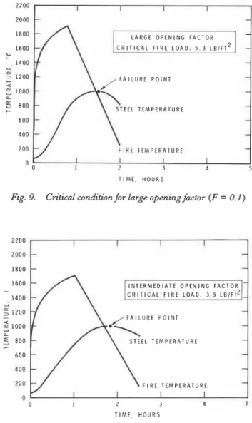
Two major parameters determine the severity of venti- lation-controlled fires. The first is related to the dimensions of the window opening and is generally known as the "opening factor"; the second is the fire load.* Figure 4 il- lustrates how the opening factor affects the fire temperature course (with the same available fire load): a large opening factor results in a fire with relatively high temperatures but short duration; a small opening factor produces a fire with relatively low temperatures and long duration. This clearly illustrates why the fire load concept, as previously discussed, is insufficient for rational fire resistance design of building structures.
Figure 5 shows the temperature course of a fire in a compartment with an intermediate opening factor, illus- trating the effect of fire load on fire severity. T h e opening factor affects the intensity and duration of the fire, but the fire load affects only duration; that is, the higher the fire load, the longer the time that elapses before the fire starts to decay. The effect of this more realistic fire representation on the behavior of structural steel elements can now be examined.
*
Here and in subsequent sections,fire load means the weight of wood with heat content equivalent to that of the combustible material per unit area ofthe bounding sul-faces ofthe fire com- partment.TIME. H O U R S
2 3
T I M E HOURS
I I I I
-
-LARGE OPENING FACTOR
-
-
-
Fig. 5. Characteristic temperature curvesfor various f r e loads Fig. 7. Characteristic temperature curvesfor various opening factors (ftre load 4.7 Ibs/ft2)
STEEL TEMPERATURES
Temperature rise in protected steel columns exposed to fires of varying severity was determined by both calculation and experiment. Calculations were based on a numerical pro- cedure.13 Columns were W12X19O sections protected by 1-in. pressed vermiculite board (density 27 lbs/ft3, specific heat 0.3 Btu/lb OF, thermal conductivity 0.108 Btu/ft hr OF) with a standard fire resistance of 3.15 hrs according to
Eq. (7a).
Results are shown in Fig. 6, with standard experimental data taken from a previous study20 superimposed for comparison. Curves 1 and 2 are the steel temperatures measured during exposure at two levels on the column.
Note that at about
llh
hrs, when the fire had started todecay, the temperature of the steel continued to rise until it reached the critical temperature at about 3 hrs. Curve 3 was obtained from a numerical analysis of the experimental situation. It accurately approximates the measured data, illustrating the excellent results that can now be obtained by calculation.
MEASUREO STEEL TEMP, (ACTUAL FIRE, HEIGHT LEVEL II
2 MEASUREO STEEL TEMP I A C T U A L FIRE. HEIGHT LEVEL 21 3 CALCULATED STEEL TEMP (ACTUAL FIRE1
4. MEASURED STEEL TEMP. [ S T A N D A R D FIRE1
0 0 5 1 1 5 2 2 5 3 3 5 4 4 5
T I M E . H O U R S
Fig. 6. Calculated and exfierimental temperature rise of protected steel column
Having demonstrated the reliability of the calculation procedure, analyses were carried out to determine the temperature rise in a W10X49 steel column for a fire load of 4.1 lbs/ft2 (20 kg/m2) for three opening factors*: large ( F = 0.1), intermediate ( F = 0.05), and low (F = 0.02), as shown in Figs. 7 and 8.
With a large opening factor, structural failure cannot occur; with an intermediate opening factor, it occurs at llh hr; and with a low opening factor, at 2Y3 hr. It is clear that the temperature rise in steel resulting from fires of different severity differs markedly from that anticipated by the fire load concept.
*
Openingfactor is defned as:A *
F = - AT where A = window area
H = window height AT = area of walls andfloors
-
-
-
--
-
- -
SMALL OPENING FACTOR
T R I T I C A L STEEL TEMPERATURE INTERMEDIATE OPENING FACTOR
-
- - - 0 0 1 2 3 T I M E , HOURSFig. 8. Effect of opening factor on steel temperature @re load 4.7 lbs/ft)
39
APPLICATION IN DESIGN
It has been shown that the opening factor has a significant effect on the steel temperature of protected columns: the higher the opening factor, the lower the steel temperature. An attempt will now be made to interpret this finding with respect to standard fire endurance and application in building design. Because of the infinite possibilities in- volved, however, any approach must be undertaken on a probabilistic basis.
For tall or otherwise large buildings, the probability of a structural failure as a result of burn-out of the contents should be kept very low, from both the point of view of occupant safety and preservation of property. The latter concept was first investigated by Lie,lo who established design fire load factors on the basis of loss expectation. T o determine the probability of structural failure, it is neces- sary to establish the fire load that will cause failure of structural elements, i.e., the fire load that will raise the steel temperature to the critical level.
Such critical fire loads have been calculated by methods described el~ewhere.".'~ The corresponding fire and steel temperature courses for the WlOX49 column are shown in Figs. 9, 10 and 11. Critical fire loads are as in Table 2.
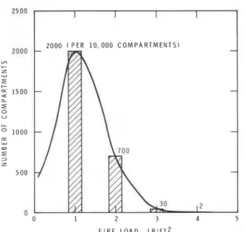
Each fire load has a certain probability of occurrence and a certain probability of being exceeded. A typical frequency of fire loads for offices, derived from preliminary surveys by the U. S. National Bureau of Standards1 is shown in Fig. 12. (These data are used by way of illustration and should not be considered applicable to all office buildings.) Figure 12 indicates that per 10,000 there are about 2000 com- partments with a fire load of 1 lb/ft2; 700 compartments with a fire load of 2 lbs/ft2; 30 compartments with a fire load of 3 lbs/ft2; two compartments with a load of 4 lbs/ft2; and a very small number with a higher fire load. According to the distribution shown (mean 1 lb/ft2, standard deviation 0.7 lb/ft2), the probability of exceeding the critical fire loads (previously calculated) are shown in Table 3.
Large (0.1) 5.3 Ibs/ft2 Intermediate (0.05) 3.5 Ibs/ft2
TABLE 3
a F'robability of exceeding the critical fire load is same as the prob- ability of collapse. Opening Factor ~ R(0.1 C) Intermediate (0.05) Small (0.02) -L A R G E O P E N I N G F A C T O R C R I T I C A L F I R E L O A D : 5 . 3 L B I F T ' T I M E . H O U R S
Fig. 9. Critical condition for large opening factor ( F = 0. I)
Critical Fire Load
5.3Jbs/ft2 3.5 Ibs/ft2 2.7 Ibs/ft2 0 0 1 2 3 4 5 T I M E . H O U R S Probabilitya less than one per
million two per ten
thousand eighty per ten
thousand I I I I
-
-
-
-
-
-
S T E E L T E M P E R A T U R E - --
F I R E T E M P E R A T U R EFig. 10. Critical condition for intermediate opening factor
(F = 0.05) S M A L L O P E N I N G F A C T O R C R I T I C A L F I R E L O A D : 2 . 7 L B I F T ~ -
-
F A I L U R E P O I N T --
T E M P E R A T U R E-
- F I R E T E M P E R A T U R E - T I M E . H O U R SFig. 1 I. Critical condition for small opening factor ( F = 0.02)
40 ENGINEERING JOURNAL I AMERICAN INSTITUTE OF STEEL CONSTRUCTION
1 0 . 0 0 0 C O M P A R T M E N T S )
-
-
-
-
11 0 1 2 3 4 5Fig. 72. Typicalfrequency distribution offire load in ofices
It is now possible to assess the value of protected columns
with a standard fire endurance of
llh
hrs. With a smallopening factor, collapse will occur in 80 of 10,000 fires; with an intermediate opening factor, in two of 10,000 fires; and with a large opening factor the possibility of collapse is negligible. Thus, if the required probability of failure is known, the critical fire load can be determined for each situation. From this, the required fire resistance, and protection (if needed), can be derived for each member or group of similar members.
CONCLUSION
Analysis based on a realistic assessment of fire behavior can form a rational basis for the design of structural fire pro- tection of buildings, provided a design probability for failure
is specified - by building codes, for example. The ac-
ceptable probability of failure depends on the value at risk and community standards (particularly for tall buildings where collapse could result in multiple deaths).
Given the required regulatory information, it is possible to proceed with design based entirely on scientific and en- gineering methods. These methods enable interpretation of the performance of steel members under standard test conditions for other conditions met with in practice, so that good use can be made of the considerable standard fire test data concerning protective materials that have been accu- mulated over the years.
REFERENCES
1 . Byson, J. 0 . and D. Gross Techniques for the Survey and
Evaluation of Live Floor Loads and Fire Loads in Modern
Office Buildings National Bureau of Standards, Building Science
Series 76, Washington, 7967.
2. Cuomo, S. Resistenza a1 Fuoco della Strutture e sua Determi-
nazione EPC-Edizionidi Protezione Civile, Rome, 1968, pp.
707-107.
3. Geilinger, E. and W . Geilinger Feuersicherkeit der Stahlkon-
struktionen II Teil, Sweizer Stahlbauuerband, Mitteilungen der
Technischen Kommission, Heft 75, Zurich, 1956, pp. 7 7-73. 4. Harmathy, T. Z . Deflection and Failure of Steel-Supported
Floors and Beams in Fire American Society for Testing and
Materials, Special Technical Publication 422, 1967,
pp.
40-62.5. Harmathy, T . Z. and T . T . Lie Fire Test Standard in the Light
of Fire Research American Society for Testing and Materials,
Special Technical Publication 464, 7970,
pp.
85-97.6. Harmathy, T. Z . and W . W. Stanzak Elevated-Temperature
Tensile and Creep Properties of Some Structural and Pre-
stressing Steels American Society for Testing and Materials,
Special Technical Publication 464, 1970, pp. 786-208. 7. Harmathy, T. Z . and W . W . Stanzak Behaviour of Steel Flex-
ural Members in Fire Application of Solid Mechanics, Study No.
7, Proceedings of Symposium, University of Waterloo, Canada,
7972, PP. 297-3 70.
8. Ingberg, S. H. Tests of the Severity of Building Fires Quarterly, National Fire Protection Axsociation, Vol. 22, 7928, pp. 43.
9. Lie, T . T . Fire and Buildings Applied Science Publishers Ltd., London, 1972.
10. Lie, T. T . Optimum Fire Resistance of Structure Journal of the Structural Division, ASCE, Vol. 93, No. ST7, Proc. Paper 8638. Jan., 7972, pp. 275-232.
1 1 . Lie, T . T . Characteristic Temperature Cruves for Various Fire
Severities Fire Technology, Vol. 70, No. 4, 1974,
Pp.
375-326.12. Lie, T . T . and D. E. Allen Calculation of Fire Resistance of
Reinforced Concrete Columns National Research Council of
Canada, Division of Building Research, NRCC 72797, August
7972.
13. Lie, T. T . and T. Z . Harmathy A Numerical Procedure to
Calculate the Temperature of Steel Columns Exposed to Fire
National Research Council of Canada, Division of Building Research, NRCC 72535, Ottawa, 7972.
14. Lie, T . T . and T . Z . Harmathy Fire Endurance of Concrete-
Protected Steel Columns Journal ofthe American Concrete Zn-
stitute, Jan. 1974, No. 7,pp. 29-32, Proceedmgs V . 71.
15. Lie, T . T . and W. W . Stanzak Fire Resistance of Protected Steel
Columns Engineering Journal, American Institute of Steel
Construction, Vol. 70, Third Quarter, 7973, pp. 82-94.
16. Magnusson, S. E. and 0 . Pettersson Kvalificerad Brandteknisk
Dimensionering av Stalbarverk Bulletin 7 7, Lund Instttute of
Technology, Lund, 7969.
17. Pearce, N . S. and W . W . Stanzak Load and Fire Test Data on
Steel-Supported Floor Assemblies Symposium on Fire Test
Methods-Restraint & Smoke 7966, ASTM STP 422, Am. Soc. Testing Mats., 7967.
p.
5.18. Standard Methods of Fire Tests of Building Construction and
Materials 7973 ASTM Book of Standards, American Societyfor
Testing and kiaterials, ASTM E- 779- 73, 7973.
19. Stanzak, W . W. and T. T. Lie Fire Resistance of Unprotected
Steel Columns Journal of the Structural Division, ASCE, Vol.
99, No. ST5, Proc. Paper 9779, May 7973, pp. 83 7-852. 20. Stanzak, W . W . and T. T. Lie Fire Tests on Protected Steel
Columns with Different Cross-sections National Research
Council of Canada, Division of Building Research, NRCC
73072, Ottawa, 7973.
21. Steel Structures for Building Canadian Standards Association,
Ottawa, Canada, CSA S76- 7969.
22. Witteveen, J. Brandveiligheid Staalconstructies Centrum Bouwen in Staal, Rotterdam, 7966.
4 1
ACKNOWLEDGMENTS
This paper is a contribution from the Division of Building Research, National Research Council of Canada, and is published with the approval of the Director of the Division.
APPENDIX: NOMENCLATURE A = area, ft2/ft
C = heat capacity of steel core of column per unit height, Btu/ft O F
c = specific heat; without subscript that of concrete, Btu/lb O F
D = developed perimeter; without subscript inner perimeter of protection. in.
E = modulus of eiasticity, ksi
A H = activation energy of creep, Btu/lb mole I = moment of inertia of steel elements, in.4 L = one-fourth of inner perimeter of concrete
protection, ft
1 = thickness of protection, in.; also thickness of concrete cover, ft
k = thermal conductivity of concrete at room temperature, Btu/ft hr O F
p
= perimeter; without subscript: inner perimeter of concrete protection, ftR = gas constant, Btu/lb mole O F
S
= span of joist or truss, in.s = length of key member or panel, in. T = temperature,
"
FW = weight of steel per ft length, lbs/ft
Z = Zener-Hollomon parameter, of a key member in the case of trusses, and of the centre in the case of beams, hr-'
e
= T-
6811 800X = slenderness ratio
p = density, lbs/ft3
cr = stress, ksi
7 = fire resistance, min. or hr
Subscripts: a = allowable c = of concrete cr = critical d = of deck o = at 68°F s = pertaining to steel T = at temperature T