Publisher’s version / Version de l'éditeur:
Canadian Geotechnical Journal, 15, 2, pp. 306-309, 1978-05
READ THESE TERMS AND CONDITIONS CAREFULLY BEFORE USING THIS WEBSITE. https://nrc-publications.canada.ca/eng/copyright
Vous avez des questions? Nous pouvons vous aider. Pour communiquer directement avec un auteur, consultez la
première page de la revue dans laquelle son article a été publié afin de trouver ses coordonnées. Si vous n’arrivez pas à les repérer, communiquez avec nous à PublicationsArchive-ArchivesPublications@nrc-cnrc.gc.ca.
Questions? Contact the NRC Publications Archive team at
PublicationsArchive-ArchivesPublications@nrc-cnrc.gc.ca. If you wish to email the authors directly, please see the first page of the publication for their contact information.
NRC Publications Archive
Archives des publications du CNRC
This publication could be one of several versions: author’s original, accepted manuscript or the publisher’s version. / La version de cette publication peut être l’une des suivantes : la version prépublication de l’auteur, la version acceptée du manuscrit ou la version de l’éditeur.
Access and use of this website and the material on it are subject to the Terms and Conditions set forth at
Undrained strength anisotropy in embankment stability analysis
Law, K. T.
https://publications-cnrc.canada.ca/fra/droits
L’accès à ce site Web et l’utilisation de son contenu sont assujettis aux conditions présentées dans le site LISEZ CES CONDITIONS ATTENTIVEMENT AVANT D’UTILISER CE SITE WEB.
NRC Publications Record / Notice d'Archives des publications de CNRC:
https://nrc-publications.canada.ca/eng/view/object/?id=d24e1f56-b254-462a-b545-5acd133b0c1a https://publications-cnrc.canada.ca/fra/voir/objet/?id=d24e1f56-b254-462a-b545-5acd133b0c1aNational Research
Conseil
national
I
+
Council Canada
de recherches Canada
UNDRAINED STRENGTH ANISOTROPY IN EMBANKMENT
STABILITY ANALYSIS
by K. Timgaw
Reprinted from
Canadian Geotechnical Journal Vol. 15, No. 2, May 1978 p. 306-309
DBR Paper No. 767
Division of Building Research
NOTE
Undrained strength anisotropy in embankment stability analysis
K. TIM LAWDivision of Building Research, National Research Council of Canada, Ottawa, Ont., Canada K I A OR6
Received May 9, 1977 Accepted January 11, 1978
An approximate stability analysis taking strength anisotropy into account is proposed, from which various correction curves are established. Examination of these curves shows that there is one particular constant correction factor applicable to most practical situations of embanknient construction. This can be written ass, = 0.95Cm where S, is the available subsoil strength and C ,
the mean strength from the vertical and horizontal specimens. This expression is shown to be in agreement with existing field experience.
Une mirhode approximative d'analyse de stahilit6 qui dent compte de I'anisorropie deksis- lance etqui a ~ r m i s demertre au point diversesrourbesdecorrection est proposie. L'examen de ces couhes montre qu'il existe en ~articulier un facteurdecorrection consrant qui est applicable
aux cas les plus pratiques deconsrmction d e remblais. Cette correction se prksente sous la forme suivante: S, = 0.95Cm ou S. esl la resi.stance d i ~ p n i b l e dans la fondation et C,est la resistance mediane pravenant d e mesures surdes ichanrillons horizontaux el vcrticaux. TI est dimontk que cettc expression est cn accord avec les observations de CAS existant5 en nature.
Can. Geotech. J . , 15,306-309(1978)
Introduction
Recent research in undrained shear strengths demonstrates that strength anisotropy and rate effect are of great importance in the stability of embankments founded on soft clays. An attempt to account for both factors has been based on records of failure from which an empirical rela- tionship was established (Bjerrum 1972; Dascal and Tournier 1975). As shown by Schmertmann (1975), this approach is subject to a number of uncertainties that might invalidate its general application. To improve the approach, it is neces- sary to study each factor separately. This note proposes a correction factor for the effect of anisotropy.
Stability Considerations with Anisotropy
Studies to establish a functional relationship for strength anisotropy in soils have been conducted by a number of researchers (e.g. Casagrande and Carrillo 1944; Lo 1965; Davis and Christian 1971 )
.
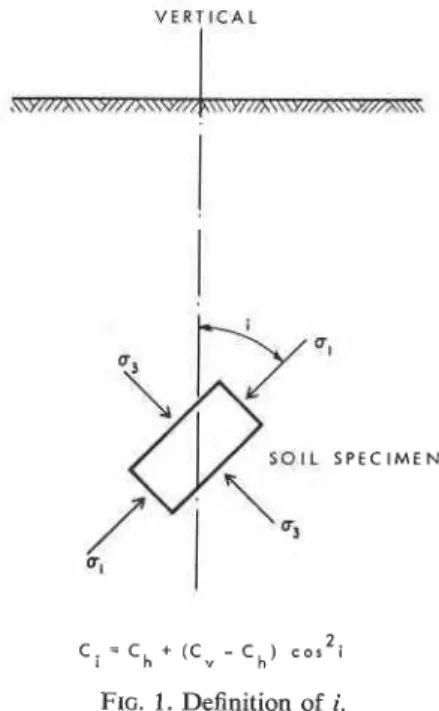
In this study, a functional relationship in terms of the square of the direction cosine (Lo 1965) is assumed. With reference to Fig. 1, the strength variation is written as
[ l l Ci = C,,
+
( C , - C1,) cos2 iwhere i is the angle between the major principal stress and the vertical and C,., C,,, Ci are the strengths for vertical, horizontal and inclined specimens, respectively ( C , and C,, can also be
V E R T I C A L
FIG. 1. Definition of i.
determined from active and passive tests on vertical specimens).
Consideration of moment equilibrium of an embankment on the soil (Fig. 2) leads to the following approximate expression of the safety factor F:
NOTE
FIG. 2. Definition of geometric parameters for stability analysis.
where: r is the radius of the slip circle; 201 is the
subtended angle at the centre of the slip surface laying in the subsoil; h,
rf
are the height and density of the embankment, respectively.Derivation of the foregoing equation is based on a critical circular slip surface represented by the midpoint circle ( ~ a y i o r 1937), on a vertical ten- sion crack through the embankment and on r being greater than 12.
Noting that i =
P
- 0, whereP
is the angle between the failure plane and the minor principal stress (Fig. 2 ) , one obtains from [2]where S ; , , the average available strength over the slip surface, is given by
+
--sin 2u cos 2 84Ra
1
where R = C,/Cl,.
Minimizing F gives an expression for evaluating
a, that is,
with 0
<
a< J2.
For an isotropic soil, R = 1 and a = 66.8". With substitution in 131, one obtains a stability number, C,./Fyfh = 0.181. This is identical to Taylor's findings ( 1937) for this particular case. A similar observation was also made by Menzies
( 1976) for a bearing capacity problem.
For the anisotropic case, evaluation of CY requires
3 knowledge of the value of
P.
Undrained testswith consolidation pressure at or below the in situ value have been reported by Lo (1965), Wong
(1972), and Law and L o (1976). In these tests
p was found to lie between 50 and 60" with a probable mean of about 56". These values were used in computing and the results are shown in Fig. 3. It can be seen that a lies in a narrow range
of about 58-70". Table 1 shows some values of
a from failure records obtained from investigations
in which an attempt was made to locate the failure surface. Although the records cover a reasonably wide range of plasticity index, the observed value of CY falls within the computed limits.
Estimating Correction Due to Anisotropy
Though S;, can be computed using [ 4 ] , simpli- fication will result if the following general equation expressible in graphical form is considered:
where C,. = C,, C I , or C,,,; C,,, is the arithmetic mean of C,. and C,,; and p., is the correction factor
5 0
oi
I .O 2 . O 3 .OS T R E N G T H R A T I O . C v / C h
308 C A N . GEOTECH. J. VOL. 15, 1978
TABLE I . Values of a observed from actual failures
Index properties (%) *Method of
locating slip
Site W WL WP IP surface K Reference
Rupert 40 33 19 14 1,
v
57 Dascal andTournier (1975)
Portsmouth 50 38 22 16 V 60 Ladd (1972)
Saint-Alban 73 47 25 22
c,
v ,w
60 LaRochelle etal. (1974)
Matagami 90 85 38 47 P 66 Dascal et a[.
(1 972)
Bangkok 140 150 65 85 W 55 Eide and
Holmberg (1972)
'C
-
cone penetrometer, 1 :-inclinometer, P-
piezometer. V = field vane, W = wood sticks.corresponding to C,).. In the case of C,,,, for 2 . 0 -
instance,
1 . 8
c71 Pn1 = 1
+
( R-
2(R 1) sin 20: cos 28+
1 ) T . -1 . b
where a is-determined from [5] or Fig. 3.
1 . 4
It should be noted that by virtue of the integra-
tion in [2], the variation of strength along the slip a
surface is taken into account when p , in [6] is used.
"
1 . 20
This is different from the correction factor pro-
posed for a similar purpose by Bjerrum (1972) in I , o
which case p varies from point to point along the
slip surface. Equation 6 proposed here is therefore o , 8
much easier to apply. = 0
Figure 4 shows the variations of p with typical "
0.6
values of R at p = 56". Depending on the strength
chosen, the correction factor may vary from 0.6 to
1.8. In other words, an indiscriminate choice of 0 4
strength value without due regard to anisotropy
may result in a wide range of possibilities from an 0 . 2
underestimation of about 60% to an overestima-
tion of 4 0 % . o I I ,
,
I , I ,,
, I,
I I-
-
P : 5 6 .-
-
P hG
*
'
:
-
-
/
-
/ '-
-
\-
\ ./' - - '\\, ./-
-
1
'
.
/ ''..
P m ; SJCm-
-
.
.
.
-
----
--
-
--
P , = S,,'C"-2---
-
-
-
-
- - +-
-
-
-
l l l l I 1 l L ~ l ~ ~ l l I 0 1 .O 2 . 0 3 . 0 Of particular interest in Fig. 4 is the relativeS T R E N G T H R A T I O . c V c,,
insensitivity of p,,, to the strength ratio. Within
practical limits, therefore, a single approximate FIG. 4. Various correction curves for a n i s o t r o ~ ~ .
correction factor of 0.95 is deemed adequate.
Hence, The first case is a failure of an embankment in
Portsmouth, New Hampshire, constructed over a
[gal S, = 0.95C1,, soft sensitive marine deposit (Ladd 1972; Ladd and
Foott 1974). C , and C,, were determined with the or
consolidated undrained, plane strain active and pas-
Lab1 S, = 0.48(C,.
+
C,,) sive tests, respectively. Using the mean of C,. andC,,, a safety factor of 0.95-1.02 was found, de-
Case Histories pending on the method of analysis. This record
The close agreement as derived in the previous definitely supports [8].
section between the available strength accounting The second case, also reported by Ladd and
for anisotropy, S;,, and the arithmetic mean of C , Foott (1974), is a stable test embankment on
tests, was used in the stability calculation -with a resulting safety factor of 1.5. Comparing the re- sults from other strength data (field vane and unconfined compression), the authors concluded that the mean of C , and C,, gave an assessment most consistent with the observed performance of the embankment. This record is again in line with the finding of the last section.
Summary and Conclusion
Strength anisotropy is important in embankment stability. Indiscriminate use of any strength may lead to either overconservative or dangerous con- sequences. When the slip surface is circular with subsoil strength defined in terms of the square of the direction cosine [I], three correction curves are established, depending on the strength used. These curves give correction factors that would account for the strength variation along the entire \lip surface. Of particular importance is the cor- rection factor based on the mean strength from vertical and horizontal specimens or, alternatively, from sctivc and passive tests on vertical specimen<. This factor has been shown lo be relatively con- stant over the usual range of anistropy and found
to be colisistent with field experience.
Acknowledgement
This paper is a contribution from the Division of Building Research, National Research Council of Canada, and is published with the approval of the Director of the Division.
BJERRUM, L. 1972. Embankmentson soft ground. Proceedings, ASCE Specialty Conference on Performance of Earth and Earth-supported Structures, Purdue University, Lafayette, 1-N, Vol. 2, pp. 1-54.
CASAGRANDE, A.. and CARRILLO, N. 1944. Shear failure of anisotropic soils. Journal of the Boston Society of Civil En- gineers, XXXI(2). pp. 74-87. Also 1953. In Contributions to soils mechanics 1941-1953. Boston Society of Civil En- gineers. pp. 122-135.
and sensitive clay foundation. ASCE Journal of the Geotech- nical Engineering Division, 101(GT3), pp. 297-3 14.
DASCAL, O., TOURNIER, J. P., TAVENAS, F.,and LAROCHELLE, P. 1972. Failure of a test embankment on sensitive clay. Proceedings , ASCE Specialty Conference on Performance of E a ~ t h and Earth-supported Structures, Purdue University, Lafayette, IN,Vol. 1, Part 1, pp. 129-158.
DAVIS, D. H., and CHRISTIAN, J . T. 1971. Bearing capacity of anisotropic cohesive soils. ASCE Journal of the Soil Mechanics and Foundations Division, 97(SM5), pp. 753-769. EIDE, O.,and HOLMBERG, S. 1972. Test fills tofailure on the soft
Bangkok clay. Proceedings, ASCE Specialty Conference on Performance of Earth and Earth-supported Structures, Pur- due University, Lafayette, IN, Vol. l , Part l , pp. 159-180. LADD, C. C. 1972. Test embankment on sensitiveclay. Proceed-
ings, ASCE Specialty Conference on Performance of Earth and Earth-supported Structures, Purdue University, Lafi~yette, IN, Vol. 1, Part I, pp. 101-128.
LADD, C. C., and F o o r ~ , R. 1974. New design procedure fol- stability of soft clays. ASCE Journal of the Geotechnical Engineering Division, lOO(GT7). pp. 763-786.
LAROCHELLE, P., TRAK, B., TAVENAS, F., and ROY, M. 1974. Failure of a test embankment on a soft sensitive Champlain clay deposit. Canadian Geotechnical Joutnal, 11, pp. 142-164.
LAW, K . T., and Lo. K. Y. 1976. Analysis of shear-induced anisotropy in Leda clay. Proceedings, Conference on Numer- ical Methods in Geomechanics, Blacksburg, VA, Vol. 1, pp. 329-344.
Lo, K. Y. 1965. Stability of slopes in anisotropic soils. ASCE Journal of the Soil Mechanics and Foundations Division, 91(SM4), pp. 85-106.
MENZIES, B. K. 1976. An approximate correction for the influence of strength anisotropy on conventional shear vane measurements used to predict field bearing capacity. Geotechnique, 26, pp. 63 1-634.
S C H M E R T M A N N , J . H. 1975. MeaSurement of in-situ shear strength. Proceedings. ASCE Specialty Conference on It~-sirrt Measurements of Soil Propet-ties, North Carolina Univet-sity, Raleigh, NC, Vol. 11, pp. 57-138.
TAYLOR, D. W. 1937. Stability of earth slopes. Joutnal of the Boston Society of Civil Engineers, XXlV (3), pp. 197-246. A l s o 1940. In Contributions to soil mechanics 1925-1940.
Boston Society of Civil Engineers. pp. 337-386.
WONC~, P. K. K. 1972. Strength and stress-strain relations of a sensitive clay. Ph.D thesis, Civil Engineering Department. Queen's University, Kingston, Ont.