Publisher’s version / Version de l'éditeur:
2010 NCSL International Workshop and Symposium, pp. 1-9, 2010-08-25
READ THESE TERMS AND CONDITIONS CAREFULLY BEFORE USING THIS WEBSITE.
https://nrc-publications.canada.ca/eng/copyright
Vous avez des questions? Nous pouvons vous aider. Pour communiquer directement avec un auteur, consultez la
première page de la revue dans laquelle son article a été publié afin de trouver ses coordonnées. Si vous n’arrivez pas à les repérer, communiquez avec nous à [email protected].
Questions? Contact the NRC Publications Archive team at
[email protected]. If you wish to email the authors directly, please see the first page of the publication for their contact information.
NRC Publications Archive
Archives des publications du CNRC
This publication could be one of several versions: author’s original, accepted manuscript or the publisher’s version. / La version de cette publication peut être l’une des suivantes : la version prépublication de l’auteur, la version acceptée du manuscrit ou la version de l’éditeur.
Access and use of this website and the material on it are subject to the Terms and Conditions set forth at AC shunt calibrations at NRC
Filipski, Peter S.; Boecker, Michael
https://publications-cnrc.canada.ca/fra/droits
L’accès à ce site Web et l’utilisation de son contenu sont assujettis aux conditions présentées dans le site LISEZ CES CONDITIONS ATTENTIVEMENT AVANT D’UTILISER CE SITE WEB.
NRC Publications Record / Notice d'Archives des publications de CNRC:
https://nrc-publications.canada.ca/eng/view/object/?id=4c78bc64-0773-48d1-aa1b-df171459ad85 https://publications-cnrc.canada.ca/fra/voir/objet/?id=4c78bc64-0773-48d1-aa1b-df171459ad85
AC Shunt Calibrations at NRC
Speaker/Author: Peter S. Filipski
Institute for National Measurement Standards, National Research Council Canada 1200 Montreal Rd. Bldg M-36, Ottawa, ON Canada K1E 2X2
[email protected] phone: 613 993 2313 fax: 613 952 1394 Co-Author: Michael Boecker, National Research Council Canada
Abstract
NRC offers calibration of ac shunts from milliamperes up to 100 A, in the 10 Hz to 100 kHz frequency band with expanded uncertainties between 10 µA/A for currents in the milliampere range to 50 µA/A at 100 A and 100 kHz. The paper describes the design of NRC ac standard shunts, as well as NRC experience in calibrations of commercial shunts. The ac-dc difference of some commercial low current shunts is load sensitive at higher frequency ranges. The paper discusses reasons for this sensitivity and suggests mitigating solutions.
1. Introduction
The new ac current shunts appearing on the market have created a demand for accurate shunt calibrations in a wide band of ranges and frequencies: from milliamperes up to 100 A, at frequencies up to 100 kHz. To meet this demand the National Research Council Canada (NRC) manufactured a new set of standard ac shunts and upgraded its ac-dc current comparator.
The NRC shunts have been previously described in detail in our publications, [1-3]. The high-accuracy calibration of ac/dc shunts is not trivial [4], and a significant improvement in its range and significant reduction in uncertainty was achieved thanks to a joint effort of the metrological community. NRC, as other National Metrology Institutes (NMI) and manufacturers, is a beneficiary of these advances. The prototype of a commercial transconductance amplifier was developed at NIST [5], NRC low current shunts follow a design proposed by the NMI of Sweden (SP) [6], medium range shunts design was developed by NMIs of Russia (VNIIM), Australia (MIA) [7] and Sweden [8], and high-current shunts were developed by the NMI of Austria (BEV) [9]. An exhaustive list of references can be found in the mentioned publications. In this paper we concentrate on practical aspects of shunt calibrations.
2. Standard Wideband AC Shunts
NRC standard wideband ac shunts have been build in house, either from discrete resistors or from a resistive foil. Depending on the current range, three different configurations were used. For low currents, (10 to 50) mA, shunts were build using surface mount resistors. Shunts for medium range currents, (0.5 to 10) A, were assembled from bulk metal foil resistors. The high current shunts, (20 to 100) A, are of a cylindrical coaxial design, and have been manufactured using a manganin foil.
2.1 Low current shunts 10 mA – 200 mA
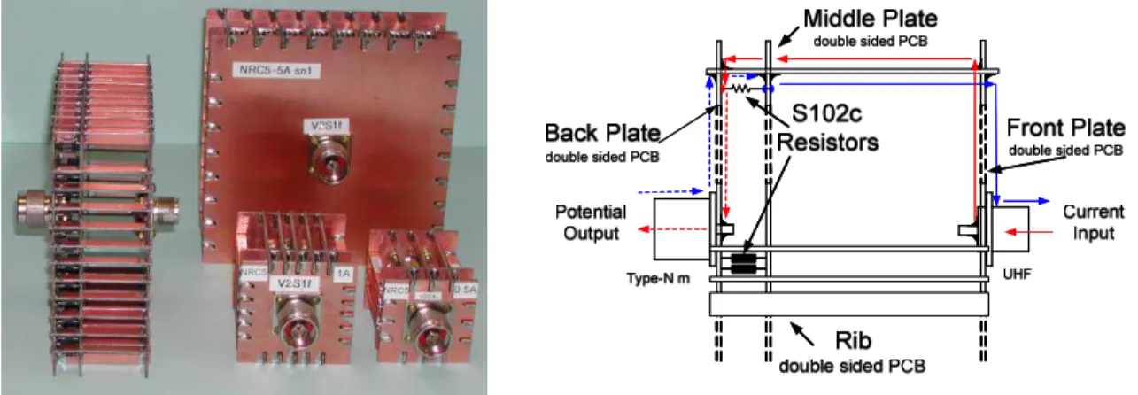
Fig. 1 shows, as an example, the design of a 200 mA shunt. The shunt consists of eight surface mount resistors, Vishay type VSM2110, arranged in a star-like configuration between two copper annuli etched on a small single-sided printed circuit board. The board is attached to an input type-N female connector and mounted in a component box. The (10, 20, 50, 100) mA shunts are build in the same form, with 10 mA shunt containing four rather than eight resistors.
2.2 Medium range shunts 500 mA – 10 A
The design of the medium range shunt is shown schematically in Fig 2. The structure of the shunt consists of three parallel plates, one at the current input and two at the voltage output, connected by several parallel ribs. The plates and the separators are made of a double-sided printed circuit board. The resistors of the shunt, type Vishay S102C, are soldered between the two output plates. The current enters through the UHF-type input connector, mounted on the input plate, and splits between several almost identical paths, equal to the number of ribs. A current of each path flows through one side of a rib, produces a voltage drop on a path resistor
Fig. 1. Construction details of NRC low current shunts.
and returns through the other side of the rib. The shunt resistors are connected in parallel, low potential sides through the middle plate, high potential sides through the inner side of the output plate, the output type-N connector is mounted on the output plate. By using n parallel resistors in the construction of the shunt one can increase the total power dissipated by the shunt while using low-power, precision resistors. Because the output is spatially separated from the input and the input current is split into n equal paths, the fractional current to each resistor is supplied separately. Each resistor of the shunt is thus coupled only to an n-th fraction of the input current, thus decreasing the input-output mutual coupling n times. This coupling is often a main source of frequency error in current shunts.
Open construction of this shunt makes it vulnerable to coupling to outside objects or electromagnetic fields. We have noticed, for example, that adding to this shunt an additional protective metal shield, changes the shunt ac-dc transfer difference. We do not use such protection in our design.
2.3 High current shunts 20 A – 100 A
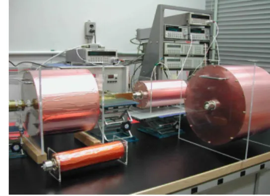
The high-current coaxial shunt is shown in Fig. 3. It consists of three thin metal-foil coaxial cylinders, formed on a solid glass-fiber epoxy cylinder. Four circular copper plates, adding to mechanical strength and stability of the structure, form parts of the input current and output voltage circuits. The cylindrical shunt resistor, made of a thin manganin foil, is placed in the middle, between two copper-foil cylinders. The input current return path is through the top copper cylinder and two input copper plates. The inner-most cylinder serves as a high-potential output voltage lead. The three cylinders are mutually insulated and connected, as required to complete the circuit, on the edges of the copper plates. The input connector is LC-type, a de-facto standard for high-current shunts; we use a type-N male connector at the shunt output. Four shunts of this design, for nominal currents of (20, 50, 80, 100) A, are part of the NRC standard shunt set.
The coaxial design is self-shielding, there is no magnetic field outside of the outer conductor. Thus there is no significant coupling of the shunt to the outside objects, such as the tested shunt, originating from the shunt current.
Placing the high potential lead cylinder inside the current cylinder has two advantages. In an
Type-N output connector Type LC input
connector
copper foil manganin foil
core input copper plates H & L output copper plates H & L Type-N output connector Type LC input connector
copper foil manganin foil
core input copper plates H & L output copper plates H & L
ideal situation, the magnetic field is contained between the two current-carrying cylinders. There is no magnetic field in the space inside the resistive cylinder, the inner conductor of the coax, thus theoretically there is no magnetic coupling between the input current and the output potential circuits. Moreover, the four-terminal inductance of the shunt does not include the inductance of the gap between two coaxial current cylinders, the gap filled by a kapton tape insulation (not shown on the drawing).
3. AC-DC Current transfer difference comparator
The design of a NRC ac-dc current transfer difference comparator, Fig.4, is very similar in design to a voltage transfer difference comparator. At the center of the comparator is a multi-range (2 mA to 100 A) wide-bandwidth (dc to 100 kHz) high-current transconductance amplifier, Clark-Hess model 8100. The range input voltage to the amplifier does not exceed 4 – 5 V at frequencies up to 100 kHz. The input sources used are Keithley model 2400 for dc and Stanford Research System model DS360 for ac. Switching the input of the transconductance amplifier between these two sources is performed by a USB-controlled mercury-wetted reed-relay.
The two compared shunts are connected in series with the output of the amplifier. One of the shunts is on the low (ground) potential and the second at the high potential, with its low terminal at the high potential output of the amplifier. The shunts are connected at the tee by their high potential current terminals. For maximum accuracy and precision, the voltages at the shunts potential outputs are measured by thermal voltage converters, TVC1 and TVC2. The outputs of the TVCs are measured by nanovoltmeters. Usually the input low terminals of both nanovoltmeters are grounded. However, at frequencies exceeding approximately 10 kHz, the capacitive leakage currents in the output circuit of the high potential shunt begin to decrease measurement accuracy. Influence of these currents on accuracy can be limited by connecting the low input terminal of the high potential nanovoltmeter to the high potential output of the
amplifier, as shown in Fig. 4. This was possible only after modification of the inner connections of the ground, guard and input low terminal of an older nanovoltmeter. The newer instruments do no allow for this modification. However, the degradation in accuracy of a comparison, while not desirable at the lowest uncertainty levels practiced at an NMI, may not significantly degrade the uncertainty budget in common situations, but its magnitude should be evaluated.
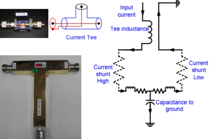
4. Current Tee
Current tee is a customary name given to a piece of hardware used to connect the output of the amplifier to the inputs of the two shunts, Fig. 5. In difference to a voltage tee, the current tee connects the shunts in series rather than in parallel. It connects low potential current terminals of coaxial shunts to either low or high potential of the amplifier and connects high potential current terminals in series. To ensure that the exactly same current flows through both shunts, the connection between the shunts should be short, with small leakage capacitance to the ground potential. This requirement is particularly important for low-current high-resistance shunts, but can be easily satisfied. A tee consisting of three connectors appropriately joined together fulfills this requirement.
At NRC we report as the final result of shunt calibration the average of two comparisons to a reference shunt, with the tested shunt in potential low and high positions. When the input connectors of the tested and reference shunts are the same this is easily done by reversing the tee. When the input connectors differ, for highest accuracy we use two asymmetrical tees in this test, one with the reference shunt in low position and one in high.
A more difficult task is a design of a current tee for high currents at high frequency. In this application the capacitive leakage current is negligible in comparison with the shunt current. However, a maximum compliance voltage of the transconductance amplifier, 7 V, becomes a limiting parameter, and an inductance of the current leads and the tee becomes an important factor. During the tests of physically large high-current shunts, the voltage drops on the shunts, the current tee (connectors) and the lead to the amplifier can be considerable. Consider the
Fig. 5. A current tee. Clockwise: a circuit diagram, an equivalent circuit, BEV high current tee, NRC low current tee.
following examples. At 100 kHz a 100-A current causes an inductive voltage drop LI of 7 V on a series inductance as low as 111 nH. In the same conditions we measure almost 1 V on a male/female LC connection and a 5.5 V voltage drop on 0.23 m (9”) of a coaxial cable RG218/U, terminated by two LC male connectors. The design of the connecting lead and the tee should thus minimize the inductance of the loop. At NRC we use a high current tee manufactured by BEV Austria, Fig. 5, which simultaneously connects both shunts to the amplifier. An approximate voltage drop on this tee, measured with side arms shorted, is 3 V at (100 A, 100 kHz), leaving up to 4 V for the voltage drop on the high-current shunts.
5. TVC ac/dc corrections
The result of comparison of two shunts on an ac-dc current transfer comparator is the difference of ac-dc current transfer differences of the reference and test shunts, ref
i tst i δ
δ − . Each of these terms contains not only the ac-dc difference of the corresponding shunt but also the ac-dc difference of the measuring TVCs, [10]. Assuming that the reactance of the shunts and an inductive coupling of the shunt and the measuring TVC circuit are small, the ac-dc current transfer difference calculated from the nanovoltmeter measurements can be expressed in the approximate form as:
R I TVC S S V TVC S TVC i R R R R R R δ δ δ δ + + + + ≈ (2)
where δV ,δI are ac-dc differences of the TVC measured as a voltage and current converter, respectively. RTVC andRS are the input resistance of the TVC and the shunt andδR is the shunt ac-dc transfer difference.
When we report the ac-dc transfer difference of a shunt we remove from the results the ac-dc transfer difference of the TVC. The end user of the shunt, when using these results in his laboratory, has to augment ac-dc shunt transfer difference from the report by the ac-dc transfer difference of his/her own measuring instrument, as per eqn. (2).
For higher-current shunts, when the shunt resistance is smaller than 20 , (i.e. 50 mA and higher currents) only the term containingδV has to be considered. Similarly, when output of the shunt is measured using an electronic instrument with high input impedance, the term with δI can be neglected.
TVCs used with NRC working standard shunts have input resistance of 220 (90- TVC combined with 130 resistor). The input resistance of the TVCs used in measuring client’s shunt output is typically 90 .
6. Standard Shunts Characterization
The standard shunts are characterized through a bootstrap process, as described in [2]. We start with a multijunction thermal converter, which can operate up to 20 mA. Its voltage and current
ac-dc transfer differences are negligible at the frequency range between 20 Hz up to 7 kHz. This frequency band is extended up to 100 kHz by comparing it to an NRC designed Calorimetric Thermal Voltage Converter. Such characterized converter is then used at 10 mA and 20 mA to characterize shunts at these ranges. The 20 mA shunt is then used to characterize a 50 mA shunt at 20 mA. In the next bootstrap step the 100 mA shunt is characterized by comparison to a 50 mA shunt at 50 mA. The process repeats, to end with the characterization of an 100 A shunt by comparison to an 80 A shunt. As each shunt is used in the bootstrap process at two levels, the TVC used to measure the shunt voltage output is characterized at two levels as well, to be able to take into account the level dependence of the ac-dc difference. This level dependence can be significant (tens of V/V) at low frequencies, below 40 Hz.
The error budget at each step of the bootstrap takes into account several components of uncertainty, such as: reference standard uncertainty, standard deviation of the comparison with the reference, test linearity, high potential/low potential position uncertainty, TVC ac-dc difference and level dependence, operating temperature variations and long term stability. Results of NRC calibration uncertainty at selected levels of current and frequency are shown in Table 1.
7. Low current shunt calibration
Equation (1) is only an approximation. It shows the ac-dc current transfer difference of a shunt-TVC combination assuming negligible parasitic reactances (capacitance and self- and mutual inductance) of a shunt. At frequencies of interest, the shunt and TVC are approximated as pure resistances. However, when this is not the case, the ac-dc transfer difference of a shunt, calculated from (1), will depend on the impedance of the output voltage measuring instrument, i.e. the TVC. This effect can be significant for low-current high-resistance shunts used at frequencies exceeding several kHz. To limit this error source, a manufacturer of ac-dc shunts would specify a nominal resistance of a TVC used for calibration, for example 90 . An electronic instrument, with high input impedance, would be fitted with an adapter, to lower its input impedance to the low input impedance of the 90 TVC.
NRC, as well as other National Metrology Institutes, striving for the highest accuracy, continue using single junction or multijunction TVCs in shunt calibrations. However, TVCs are being phased-out in the industry, and manufacturers specify parameters of shunts assuming not a low- Table 1. An example of calibration uncertainty of ac-dc shunts.
Expanded uncertainty Uc / Frequency kHz Current range A 1 10 50 100 0.01 10 10 10 10 0.1 11 12 14 16 1 13 16 19 21 10 17 17 24 28 100 18 19 36 49
impedance loading, typical for a TVC, but a high impedance loading, or an open circuit. This can create a problem in interpretation of the calibration results.
The following example from our practice shows the issue in a perspective. NRC specifies expanded uncertainty of calibration of a 10 mA shunt at 100 kHz 10 / . Recently we have calibrated such a shunt from a newly introduced shunt-set using at first a 90 TVC and later a 220 TVC, (used for NRC working standards). The results of calibration differed by approximately 25 / , 2.5 times NRC quoted expanded uncertainty. The reason for such large loading influence was traced to a relatively large residual capacitance of the commercial shunt of a new design. We learned from the client, that he was using a 160 TVC with this shunt.
As the test range of calibration of ac/dc shunts increases and the uncertainty decreases, the error budget has to include components which were not considered previously. As shown here, the systematic “loading error” can significantly exceed the expanded uncertainty of calibration, if the load used by an NMI differs from the load used by the client. If not properly taken into consideration, this will render client’s uncertainty budget unrealistic. If using the same load at NMI and the client’s laboratory is impractical, this issue can be resolved in several ways:
(a) A loading correction can be established by the calibrating laboratory, the client or the manufacturer, and the correction applied. The uncertainty budget has to be expanded by the uncertainty of the application of the correction.
(b) A client may prefer to send to the calibration laboratory his/her loading instrument (TVC) with a set of shunts and ask for a calibration report of the shunt/instrument assembly rather than the shunt alone. This is the lowest calibration uncertainty option.
(c) A “nominal load” can be established for popular shunts (for example, 160 /10pF TVC) and the calibration laboratory and the client would use such a “nominal load TVC”. Manufacturer could also decide to specify the ac-dc transfer difference of the shunts under the “nominal load”. Unfortunately, while this was the calibration practice thus far, it may no longer be practical for all clients.
8. Summary
In response to the requirements of the market place, NRC has expanded its shunt calibration capabilities to 100 A in current magnitude and 100 kHz in frequency. NRC standard shunts were custom built in-house, using three different designs for low, middle and high current ranges. Extensive tests were conducted to evaluate the influence of different components on the shunt calibration uncertainty.
While calibrating shunts introduced recently on the market, a possible problem affecting accuracy of clients calibration was identified, when a shunt calibrated using a low-impedance TVC is used in a high-impedance, or no-load, condition. We propose introduction of a “nominal load” or a table of typical corrections for shunts with non-negligible residual reactances.
References
[1] P.S. Filipski, M. Boecker, “Improvements in the AC-DC Current Transfer Capabilities at NRC,” Digest of the Conference on Precision Electromagnetic Measurements CPEM 2004, London, UK, June 27-July 03, 2004, pp.579-580.
[2] P.S. Filipski, M. Boecker, “AC-DC Current Shunts and System for Extended Current and Frequency Ranges,” IEEE Trans. Instrum. Meas., vol. 55, August 2006, pp. 1222-1227.
[3] P.S. Filipski, M. Boecker, M. Garcocz "20-A to 100-A AC-DC Coaxial Current Shunts for 100 kHz Frequency Range," IEEE Trans. Instrum. Meas., vol. 57, August 2008, pp. 1637-1641. [4] J.R. Kinard, T.E. Lipe, and C.B. Childers, “Extension of the NIST AC-DC Difference Calibration Service for Current to 100 kHz,” J. Res. NIST, vol. 102, No. 1, January – February 1997, pp. 75-83.
[5] O. B. Laug, “A 100 A, 100 kHz transconductance amplifier,” IEEE Trans. Instrum. Meas., vol. 45, June 1996, pp. 440–444.
[6] K-E. Rydler and P. Simonson, “High Accuracy Low-Voltage AC-DC Transfer Standard,” Dig. Conf. Prec. Electrom. Meas. CPEM’94, Boulder, CO, June 27- July 1, 1994, pp. 382-383. [7] S. Svensson and K-E. Rydler, “A Measuring System for Calibration of Power Analyzers,” IEEE Trans. Instrum. Meas., vol. 44, April 1995, pp. 316-317.
[8] I. Budovsky, “A Micropotentiometer-based System for Low Voltage Calibration of
Alternating Voltage Measurement Standards,” IEEE Trans. Instrum. Meas., vol. 46, April 1997, pp. 356-360.
[9] M. Garcocz, P. Scheibenreiter, W. Waldmann, G. Heine, “Expanding the Measurement Capability for AC-DC Current Transfer at BEV,” Dig. Conf. Prec. Electrom. Meas. CPEM’04, London, UK, June 27-July 03, 2004, pp.461-462.
[10] J.R. Kinard, T.E. Lipe, “AC-DC Difference Relationship for Current Shunt and Thermal Converter Combinations,” IEEE Trans. Instrum. Meas., vol. 40, April 1991, pp. 352-355.