Decision Support Systems for Tool Reuse and EOL Processes
By Jyeh J. Gan
Bachelor of Science in Electrical Engineering, Texas A&M University (1999)
Submitted to the MIT Sloan School of Management And
The Department of Electrical Engineering and Computer Science In Partial Fulfillment of the Requirements for the Degrees of
Master of Business Administration
Master of Science in Electrical Engineering and Computer Science
In Conjunction with the Leaders for Manufacturing Program at the
Massachusetts Institute of Technology
June 2007
© Massachusetts Institute of Technology, 2007. All rights reserved.
Signature of Author________________________________________________________ MIT Sloan School of Management Department of Electrical Engineering and Computer Science May 1, 2007 Certified by______________________________________________________________
Donald Rosenfield, Thesis Supervisor Senior Lecturer, Sloan School of Management Director, Leaders for Manufacturing Fellows Program Certified by______________________________________________________________ Duane S. Boning, Thesis Supervisor Associate Department Head & Professor, Department of Electrical Engineering and Computer Science Accepted by_____________________________________________________________
Debbie Berechman Executive Director, MIT Sloan MBA Program Accepted by_____________________________________________________________
Arthur C. Smith, Chairman, Department Committee on Graduate Theses Department of Electrical Engineering and Computer Science
2
3
Decision Support Systems for Tool Reuse and EOL Processes
by Jyeh J. Gan
Submitted to the MIT Sloan School of Management and the Department of Electrical Engineering and Computer Science on May 1, 2007 in Partial Fulfillment of the
Requirements for the Degrees of
Master of Business Administration
and
Master of Science in Electrical Engineering and Computer Science
Abstract
Intel® is a manufacturing company that concentrates on the fabrication process of
computer chips. Over the years and into the future, Intel® has gone through multiple and advanced generations of manufacturing technology caused by new fabrication techniques and increased wafer sizes. These advances have resulted in significant opportunities for cost reduction which includes reuse of semiconductor equipment within Intel factories and sale of used semiconductor equipment. To ensure assets are transferred in a safe and timely manner, Intel developed a 6D program (Decontamination, Decommission,
Demolition, Demolition-System, Delivery, and Deployment) to standardize the EOL (End of Life) process of transferring a tool from the factory to its final destination in re-use, sale, parts harvesting, donation or scrap.
Like other multi-national companies, Intel® has decentralized manufacturing processes over multiple worldwide sites; most if not all the fabrication, sort, and assembly tool information is archived in multiple repositories/systems. In addition to the scattering of knowledge, the tool-related information appears not to be comprehensive, including data fields not matching across multiple systems. As a result, significant time is consumed to ensure the comprehensiveness and the accuracy of the required data across the multiple sites. Thus a comprehensive map of information infrastructure based on the 6D process is necessary to understand and enhance efficiencies in the knowledge flow process. Detailed mapping of databases and their meta-data will help identify the thoroughness, accuracy, redundancy, and inefficiency in the tool-related information systems as they relate to 6D. A prototype of a “one-stop-site” was developed and key Knowledge Management recommendations were proposed to enhance efficiency by further reducing costs, time, and resources.
Thesis Supervisor: Donald Rosenfield
Title: Senior Lecturer, Sloan School of Management Thesis Supervisor: Duane S. Boning
4
5
Acknowledgements
I would like to acknowledge Intel® Corporation for providing an extraordinary learning experience at the Chandler, AZ site. My heartfelt thanks go to Rahman Khan, my internship supervisor, who provided insights, support and advice enabling me to be successful and was a hospitable host for me during my time in Arizona. In addition, I would like to thank Chuck Seeley, Michelle Ramacciotti, Mark Miera, and Robert Wright for their assistance and generosity in making my research successful and rewarding. Finally, I would like to thank the many other Intel® employees who gave their time and their expertise. This thesis represents a great deal of their effort as well as my own. The Leaders for Manufacturing (LFM) Program at MIT has wonderful faculty, staff and students. My thesis advisors, Don Rosenfield and Duane Boning, asked
thought-provoking questions and aided me throughout this internship; I thank them for all their help. My LFM, Sloan School of Management and Engineering student teams greatly enhanced this overall experience; thank you for being my colleagues and my friends. I wish to acknowledge the Leaders for Manufacturing Program for its support of this work. Dell Inc. has provided generous sponsorship for my graduate work. In addition to being my employer since 1999, the great team at Dell has provided mentorship and outstanding experiences for me in a variety of jobs. I look forward to rejoining Dell in 2007 and helping the company become even more successful.
My Mom, Dad, and both my Brothers have supported and encouraged me throughout my life, and these two years at MIT have been no different. Thank you for believing in me.
6
7
Table of Contents
ABSTRACT ... 3 ACKNOWLEDGEMENTS ... 5 TABLE OF CONTENTS ... 7 TABLE OF FIGURES ... 9 CHAPTER 1: INTRODUCTION ... 11 1.1PROGRAM BACKGROUND... 11 1.2SUMMARY OF OBJECTIVES... 11 1.3SUMMARY OF RESEARCH... 12 1.4SUMMARY OF RECOMMENDATIONS... 13 1.5THESIS OVERVIEW... 14CHAPTER 2: INDUSTRY, COMPANY, & PROGRAM BACKGROUND ... 15
2.1INDUSTRY OVERVIEW... 15
2.2COMPANY OVERVIEW... 16
2.2.1 Company History ... 16
2.2.2 Intel Today ... 17
2.2.3 Intel Culture and Strategy... 17
2.36DPROGRAM OVERVIEW... 18
2.3.1 Mission... 18
2.3.2 Organizational Structure and Program Personnel ... 19
2.3.3 Overview of the Knowledge Management Group ... 20
2.46DPROCESS OVERVIEW... 21 2.4.1 1D – Decontamination ... 22 2.4.2 2D – Decommission ... 23 2.4.3 3D – Demolition... 23 2.4.4 4D – Demolition of Utilities... 24 2.4.5 5D – Delivery... 25 2.4.6 6D – Deployment ... 26
CHAPTER 3: PROJECT SURVEY ... 27
3.1MOTIVATIONS AND CHALLENGES FOR THE PROJECT... 27
3.1.1 Objective ... 27
3.1.2 Project Motivation and Scope... 27
3.1.3 Project Challenges... 28
3.2STRUCTURING THE RESEARCH... 29
3.2.1 Methodology ... 29
3.2.2 Domains Experts & Key 6D Personnel... 31
3.2.3 Information Systems for Tools ... 32
3.3IMPLEMENTATION FRAMEWORKS FOR PROJECT SUCCESS... 32
3.3.1 Stakeholder analysis ... 33
3.3.2 Strategic Lens... 34
3.3.3 Political Lens ... 36
3.3.4 Cultural Lens ... 37
CHAPTER 4: RESEARCH FINDINGS... 40
4.16DMAP WITH INFORMATION SYSTEMS... 40
4.2OVERVIEW OF GAPS IDENTIFIED... 42
4.3SYSTEM-RELATED GAPS... 45
4.4KNOWLEDGE-RELATED GAPS... 47
8
4.6RESOURCE-RELATED GAPS... 48
4.7CONCLUSION... 48
CHAPTER 5: PROJECT RECOMMENDATIONS ... 49
5.1CLASSIFICATION OF THE RECOMMENDATIONS... 49
5.2TIER 1GAP CLOSURES... 49
5.2.1 One-Stop Shop in Knowledge View – Phase 1 ... 49
5.2.2 LookAhead Report – Manual ... 50
5.2.3 “Copy Exactly” of 6D Processes... 51
5.3TIER 2GAP CLOSURES... 52
5.3.1 One-Stop Shop/Dashboard – Phase 2... 52
5.3.2 LookAhead Report – Automated ... 54
5.3.3 Lessons Learned and Issues Tracking System... 54
5.4TIER 3GAP CLOSURES... 55
5.4.1 Next Generation the ERP System ... 55
5.4.2 Tool Disposition Selection Algorithm ... 56
5.5OTHER GAP CLOSURES... 56
5.6LONG TERM GOALS... 57
CHAPTER 6: CONCLUSION ... 58
6.1RESEARCH OF OTHER APPROACHES TO SIMILAR PROBLEMS... 59
6.2KNOWLEDGE MANAGEMENT AS PART OF A MANUFACTURING PROCESS... 60
6.3RECOMMENDATIONS FOR FUTURE WORK... 60
APPENDIX A - 6D WORK/KNOWLEDGE FLOW MAP ... 63
9
Table of Figures
FIGURE 1-SYNERGISTIC RELATION OF MITLFM&INTEL®... 11
FIGURE 2-6DPROGRAM ORGANIZATIONAL STRUCTURE... 19
FIGURE 3-6DPROCESS AND WORK FLOW... 22
FIGURE 4-OPTIONS FOR TOOL DELIVERY... 25
FIGURE 5-RESEARCH STRUCTURE... 29
FIGURE 6–METHODOLOGY FOR EXPLORATION AND VALUE DECISION PHASES... 30
FIGURE 7–SAMPLE STAKEHOLDER ANALYSIS FOR THE INTERN... 33
FIGURE 8–“U-TURN”RESULT FROM TRADITION DEVELOPMENT PROCESS17... 34
FIGURE 9–ONE ASPECT OF FAST-PACED ORGANIZATIONS21... 39
FIGURE 10-HIGH LEVEL 6DPROCESS WITH INFORMATION... 40
FIGURE 11-GAP IDENTIFICATION SCENARIO -PHASE 1... 43
FIGURE 12-GAP IDENTIFICATION SCENARIO -PHASE 2... 43
FIGURE 13-GAP IDENTIFICATION SCENARIO -PHASE 3... 44
FIGURE 14-GAP IDENTIFICATION SCENARIO -PHASE 4... 45
FIGURE 15–SAMPLE ONE STOP SHOP IMPLEMENTATION IN KNOWLEDGE VIEW... 50
FIGURE 16-DASHBOARD CONCEPT FOR THE 6DPROGRAM... 52
FIGURE 17-6DWORK/KNOWLEDGE FLOW MAP:1D&2D ... 63
FIGURE 18-6DWORK/KNOWLEDGE FLOW MAP:3D... 64
FIGURE 19-6DWORK/KNOWLEDGE FLOW MAP:4D&5D ... 65
10
11
Chapter 1: Introduction
1.1 Program Background
This thesis is the result of a six-month internship with Intel® Corporation’s 6D Program where the majority of time spent was in Chandler, Arizona. Intel® Corporation created the project with the purpose of improving the operation of the 6D Program and
completing the thesis requirements for the MIT Leaders for Manufacturing (LFM) program. In this case, the 6D Program was facing challenges in coordination and compliance and sought LFM contributions to their improvement efforts.
As can be seen in Figure 1, Intel® and MIT LFM have a truly synergistic and mutually beneficial partnership between the worlds of industry and academia. Intel® is a sponsor company for LFM and regularly utilizes LFM students as interns. The 6D Program and Knowledge Strategies and Solutions groups are integral organizations within Intel® that have played an integral role in the completion of this thesis.
Figure 1 - Synergistic Relation of MIT LFM & Intel®
1.2 Summary of Objectives
Intel® is a manufacturing company that concentrates on the fabrication process of chips. Over the years and into the future, Intel® has gone through multiple and advanced
12 generations of manufacturing technology caused by new fabrication techniques and increased wafer sizes. These advances have resulted in significant opportunities for cost reduction which includes reuse of semiconductor equipment within Intel factories and sale of used semiconductor equipment. To ensure that assets are transferred in a safe and timely manner, Intel developed a 6D Program (Decontamination, Decommission,
Demolition, Demolition of Utilities, Delivery, and Deployment) to standardize the EOL (End of Life) process of transferring tools from the factory to its final destination in re-use, sale, parts harvesting, donation or scrap.1
Like other multi-national companies, Intel® has decentralized manufacturing processes over multiple worldwide sites; most if not all the fabrication, sort, and assembly tool information is archived in multiple repositories/systems. In addition to the scattering of knowledge, the tool-related information appears not to be comprehensive, including data fields not matching across multiple systems. As a result, significant time is consumed in order to ensure the comprehensiveness and accuracy of the required data across the multiple sites.
In order to continue having “best-in-class” performance in their functions, the 6D Working Group defined an internship scope involving the identification of areas of thoroughness, accuracy, redundancy, and inefficiency in the 6D tool information infrastructure. Opportunities needed to be explored to enhance the tool information infrastructure to further reduce costs, time, and resources and increase compliance to the 6D Program. Ultimately, the 6D Program stakeholders understood that no process can ever be improved upon without first comprehending the entirety of the operation, where and why each segment of the process fit and its impact on the rest of the process.
1.3 Summary of Research
The internship objective required that the intern understand the 6D Process in detail, especially those aspects related to tool information systems. While most 6D Program members understood the 6D process from a high level, no one person could articulate
13 each and every organization, person, or system involved as tools were transferred
between sites. Thus the first several months of the internship were dedicated to gaining in-depth knowledge of the 6D process. This entailed performing numerous interviews with program managers, working group members, and experts in various tool system domains. The approach can only be described as organic in nature – each interviewee led to another who would know bits of information that others did not know. In this manner, knowledge was collected from disparate sources and compiled into a compendium of related data.
The last half of the internship was applied to the compilation of gathered knowledge and recognition of the gaps seen as the information was assembled. Upon identification of the key gaps, the intern leveraged MIT’s thought leadership on disposal of excess inventory, best practices within Intel®, and best practices from industry to specify potential solutions to aid in solving the disparities.
1.4 Summary of Recommendations
Proposed solutions offer unquantifiable benefits in cost, resources, and time to the 6D Program. Some of the benefits and recommendations are:
• An “Outsider-on-the-inside” perspective helped the 6D Working Group realize the full extent of the scattering of tool-related information and its impact upon the success of the 6D Program.
• A detailed mapping of tool information systems as related to the 6D work flow increased understanding of the overall complexity of the 6D Program for all participants.
• A prototype of a “one-stop-shop” based on a pre-existing concept was created, allowing the 6D Working Group to engender support for the program and to be able to quickly look at compliance metrics.
Research of centralized data systems indicates that the recommendations contained in this thesis are appropriate and suitable. The review of the 6D Program substantiates the research.
14
1.5 Thesis Overview
This thesis will describe the project background and activities in detail. The following chapters will be used to document findings and recommendations:
Chapter 2: Industry, Company, & Program provides an overview of the corporate and industry environment of which the 6D Program is a part. It will also detail the 6D Program and its high level work flow.
Chapter 3: Project Survey discusses the motivations and challenges for the project. It relates the methodology in which the research was conducted and environment necessary for the project’s success.
Chapter 4: Research Findings outlines the detailed mapping of the 6D work flow and reviews the project findings found during the research.
Chapter 5: Project Recommendations makes recommendations for 6D Program improvements and endeavors to identify a timeline for implementation.
Chapter 6: Conclusion explores knowledge management as a part of industry and provides final thoughts on recommendations for future work and on the research conducted.
15
Chapter 2: Industry, Company, & Program Background
This chapter provides the background necessary to understand the industry, corporate, and factory situations that impact the 6D Program’s challenges at hand.
2.1 Industry Overview
The IT industry has evolved exponentially in the last hundred years from punch cards in the 1890s to the internet in the 1990s. A key ingredient in the IT industry’s evolution is the semiconductor industry spawned by the creation of the transistor, the main
component in today’s electronics2. The transistor was invented at Bell Labs in 1947 by Bardeen, Brattain and Shockley. No other discovery in this generation has had such a profound impact on modern lives.
In the 1950s and 1960s, transistor technology exploded, generating billions of dollars in revenue and producing devices and applications which contribute in fundamental ways to modern society.3 Without transistors, there would be no personal computers, cell phones, MP3 players, etc. The integrated circuit (IC) first made by Jack Kilby of Texas
Instruments in 1958 and the first silicon IC made by Robert Noyce of Fairchild Camera in 1961 enabled the semiconductor industry to become economically viable4. Companies like TI, Motorola, Fairchild Semiconductor and GE helped the industry quickly surpass a billion dollars in sales by 1964.
This allowed for the founding of such current industry leaders as Intel®, AMD, and Samsung. A few years earlier, Gordon Moore, one of Intel®’s founders, predicted the exponential growth in chip density by doubling the transistors on a chip every two years; now popularly known as “Moore’s Law.” Although Moore's Law was only an empirical observation, the more the industry accepted it, the more it became a goal for the industry.
The 1980’s brought the advent of the personal computer (PC) and continued growth of semiconductor manufacturing. By 1994, the industry saw sales of $100 billion which
16 was quickly outdistanced by sales of $200 billion just six short years later in 2000. Over the last 50 years, the leaders of the semiconductor industry have drastically changed with some players already forgotten. Today businesses like Intel®, AMD, and Samsung compete aggressively for markets in memory technologies, processors, networking, etc.
The rapid expansion of semiconductors led to a similar advancement in semiconductor manufacturing equipment. Moore’s Law5,6 drove semiconductor manufacturers to focus enormous energy aiming for increases in processing power and driving the need for better fabrication equipment. The semiconductor capital equipment market, a $40 billion market in 2006, has businesses that manufacture high-priced, highly-specialized equipment.
2.2 Company Overview
2.2.1 Company History7
Intel® Corporation was founded in 1968 by Gordon E. Moore and Robert Noyce to manufacture semiconductors. The company was renamed to INTegrated Electronics after being called NM Electronics. Initially, Intel®’s development and production efforts were focused on memory products. However, for the past 15 years, this Fortune 100 company has developed significant brand recognition and revenue for their
microprocessors including the Pentium line of products.8
Throughout the 1980s, Intel® expanded its manufacturing facilities, improved its manufacturing processes, and manufactured a wider range of products, although most were memory devices. The birth and spread of the personal computer (PC) encouraged Intel® to diversify into the microprocessor market which proved to be one of the most financially beneficial decisions in Intel®’s history. By 2000, the Pentium®
microprocessor products dominated the PC market, especially with the “Intel® Inside” marketing campaign making Intel® a household name.
17 2.2.2 Intel Today
2005 revenues for Intel® were $38.8 billion, and the company ranked 49th on the Fortune 500 list. Intel® has expanded to over 200 facilities worldwide with an employee base of over 100,000. It operates eleven fabrication facilities (Fabs) worldwide that are managed by the Fab Sort Manufacturing (FSM) organization. The company also manages multiple assembly and test manufacturing (ATM) facilities globally, responsible for taking the goods produced by the Fabs and making them into quality products available for purchase.
2.2.3 Intel Culture and Strategy
Like most multinational companies, Intel® has developed a culture of its own in doing business. As in other high tech cultures, the use of acronyms and “tech speak” is prolific. Throughout the company and across organizational boundaries, standards for
performance and goals have been set at an extremely high level. Failure to meet those targets was generally unacceptable. This atmosphere fostered a propensity for significant internal competition amongst individuals and business units creating an intense, but highly successful work environment.
Such a fiercely competitive setting also supported a climate for risk taking and risk aversion in which new ideas were both heralded and continuously challenged by employees1. The continuous back and forth of risk taking and aversion allowed for significant business improvement through such company-wide initiatives as best known methods, or BKM’s.
From the early days, Intel® has stayed true to its core business of efficient and quality manufacturing of all its products. This extreme focus on production has forced those groups that play a supportive role to substantiate their value to the company and to the manufacturing business units. The concentration on production and desire of continuous improvement has compelled Intel® to devote more effort in the reduction of costs in capital equipment, labor and facilities. While Intel® has already started using a larger
18 non-permanent or temporary labor force and more adaptable manufacturing facilities, securing the intrinsic value of and fully utilizing its capital equipment remains a strategic aspect of Intel®’s competitive advantage.
2.3 6D Program Overview
2.3.1 Mission
Intel® is committed to continuously improving and enabling a holistic approach that encompasses the entire cradle to grave life cycle of tools, parts, equipment, systems and utilities, etc., from removal to transfer to re-install, to warehouse, resale and/or disposal.
The 6D (Decontamination, Decommission, Tool Demolition, Demolition of Utilities, Delivery, and Deployment) Program is a comprehensive initiative focused on this holistic approach, consisting of the following key components:
• Facilities, equipment, and materials reuse, resale, return, warehousing, disposal. • Successful transfer of tools between sites.
• Consistent, standardized business processes and communication flows, including auditing and investigation procedures and protocols.
• Structured knowledge capture and dissemination - systems for data and information collection, storage, and management.
• Clear roles and responsibilities for employees and contractors. • Training and certification requirements and materials.
• Indicator identification and reporting mechanisms; decision support applications. • Reduction in liability and risk.
The 6D Program is critical to Intel® for a variety of reasons. Among these is the management of capacity and assets to meet the lean and agile expectations of the company. Additionally, the extension of capital equipment lifetimes from the present two or three generations to four generations remains vital to Intel®’s future success.
19 2.3.2 Organizational Structure and Program Personnel
The 6D Program essentially exists as a three-level system, as pictured in Figure 2,
consisting of Working Groups (WG), Program Managers (PM) from CS (Corporate Services) and FSM areas, and a Management Oversight Committee (MOC). The 6D PM’s are responsible for the success of the overall program; WG and sub-working groups addresses specific aspects of the program; and the 6D MOC members ensure the
direction is correct. The MOC or Management Review Committee (MRC) has broad-based participation from multiple divisions and many professional disciplines, including:
• Engineering (Equipment and Process). • Facilities Management.
• Environmental Health and Safety. • Supply Chain Management. • Manufacturing.
• Knowledge and Information Management. • Equipment and Materials Resale.
Figure 2 - 6D Program Organizational Structure9
The 6D Working Group and sub-teams are staffed by subject matter experts and program managers representing the above professional disciplines. The working group, as well as
20
the 6D Program, is co-managed by one CS and one FSM manager. This co-leadership principle allows for the organizations’ various objectives and farther reaching influence to aid in achieving success for the program.
The 6D WG internally develops ideas and proposals to improve upon Intel®’s ability to
reuse capital assets and acquires approval for implementation of those recommendations from the MOC. The 6D MOC, made up of Directors and Senior Managers from the key stakeholder organizations, reviews and decides upon the recommendations. The MOC is briefed regularly on a quarterly basis. Because of their rank and seniority of the MOC members in their respective groups, they also play a significant role removing any operational hurdles the WG may encounter. Such an oversight committee composed of senior officials allows the 6D Program to have wider impact and acceptance.
2.3.3 Overview of the Knowledge Management Group
Knowledge Management (KM) is a systematic, structured way of creating, storing and sharing information so it can be effectively used throughout the organization to solve problems, make decisions, take action, and educate. When the principles and practices of sound KM are applied, there is successful conversion of information into value for the stakeholders and the corporation. To be effective, KM programs must involve
appropriate domain experts, prepare for process and behavior changes, and embed technological enhancements.10
The domain of KM emphasizes both explicit and tacit knowledge. Explicit or formal knowledge can be articulated in language and transmitted among individuals. It is documented, codified and easily accessible, such as a specification. On the other hand, tacit or tribal knowledge is rooted in individual experience and involves personal belief, perspective and values. It is often times considered the key to getting things done and creating new value and innovation. While estimates vary in range, one could
conservatively estimate that about 30% of critical information needed for people to do their jobs is in an explicit format, while 70% is in a tacit form - in people’s heads.10 If
21 this information were properly physically documented it could be considered a
knowledge asset. One of the goals of knowledge management is to leverage the tacit (tribal) knowledge in the organization through communities of practice and through the process of connecting those who know with those who need to know.
Managing knowledge represents a primary opportunity for achieving substantial savings, significant improvements in performance and a competitive advantage. Thus the KM Group within Intel® strove to improve processes throughout the company and across several organizational divides. The group has multiple projects simultaneously occurring in diverse businesses, most concentrating on the creation of automated tools and
standardized business processes. The KM Group has consistently shown the ability to provide a high return on investment and proven performance in the tools they provide. For this very reason, KM plays an integral in the 6D Program, which spans multiple and very distinct groups within Intel®.
2.4 6D Process Overview
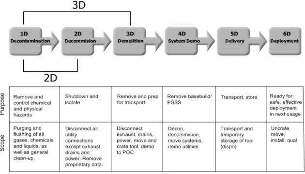
The terms: decommission, decontamination, demolition, system demolition, delivery, and deployment collectively refer to the 6D process. The 6D process describes the work flow, as shown in Figure 3, used in transferring a piece of capital equipment or tool from one location to another.
22 Figure 3 - 6D Process and Work Flow
2.4.1 1D – Decontamination
Tool decontamination and decommission are linked and often referred to as the “2D” process in the company guidelines – Virtual Factory (VF) specifications. All of the Fabs are part of what Intel® calls the VF, since the advent of the Copy Exactly standard. 1D and 2D must be connected since equipment cannot be decommissioned or shut down without decontamination steps such as venting of gas lines or removal of other dangerous chemicals.
Decontamination consists of the purging and flushing of all gases, chemicals, and liquids, as well as general clean-up. “These run the range of inert gases, such as Nitrogen (N2), to strong acids such as Hydrofluoric Acid (HF) used in etching semiconductor layers, to pyrophorics such as silane11 (HSi4) used in chemical vapor deposition (CVD)
processes.”1
Proper decontamination can be a detailed and lengthy process. “In addition to emptying the equipment lines of chemicals, equipment using large amounts of acids, called ‘wet benches’, present an additional challenge in that the bench itself frequently absorbs
23 enough acid during the production process that leaching can occur during long term storage. This means that even careful decontamination may still result in trace levels of low pH fluids accumulating. In the best-case scenarios, these levels are below the maximum allowable mandated by Intel® safety standards and government regulations governing storage and transport.”1
2.4.2 2D – Decommission
After decontaminating the tool and support equipment, all the equipment is powered down and all utility connections except exhaust, drains and electrical are disconnected from both the main tool and the support equipment (pumps, chillers, compressors, etc.). All Intel propriety information must be removed for those tools being scrapped,
harvested, or sold. Internal shipping fixtures must be added to prevent damage during shipment.
Several reasons exist for a tool to be decommissioned, including machine upgrade, failure, or replacement. The primary reason for changing a tool is technology upgrade, either in process shrink or a technology change (wafer size, Al to Cu, 90 nm to 45 nm, etc.). The 6D process is becoming of even greater importance with the large scale changeover from 200mm to 300mm manufacturing equipment.
Together, equipment decontamination and decommission consists of completing the removal and clean-up of all gases, chemicals, and liquids, and disassociating or disconnecting the tool from all factory systems except exhaust, drains, and electrical. Once completed, the equipment is now ready to be “demolished.”
2.4.3 3D – Demolition
Demolition (Demo) consists of several steps involving the dismantling of the tool. Site-specific utility demolition checklists are utilized to ensure proper procedures are followed to disconnect and decontaminate remaining utilities, such as the equipment’s exhaust, drains, and electrical, from process tools. Rigging, which consists of preparing the tool
24 for a non-clean room environment and moving the tool out of the factory, has to be performed.
All tools have to be packed which entails itemizing, protecting, and securing individual tool components into crates to prevent in-transit movement or shifting that may cause damage to critical components. Packing procedures vary based on the mode of
transportation for the tool and the tool’s ultimate destination. Some tools going to Intel® Resale Corporation12 (IRC) for sale only receive a base with protective stretch wrapping for short-term storage. Other tools receive complete crates prepared for international shipment by ocean or air. Finally, others are not crated at all if they are destined for scrap or harvest. In all cases, the final destination has to be known to understand the type of packaging and crating necessary for the tool. Each case requires specific precautions to protect the assets from environmental extremes, and includes vapor barriers, bracing, and other precautions.
Finally, all utility distribution lines, fore lines, and interconnect cables are removed between fab process tools and sub-fab support equipment (chillers, pumps, compressors, etc.) back to nearest Point of Connection (POC). Interconnect cables are those that connect the fab equipment to the sub fab. These cables are packed with the tool. The system conduits for electrical, chemical delivery and exhausts are generally demolished back to the point of connection, unless a similar tool will be used there and they can be reused.
2.4.4 4D – Demolition of Utilities
4D includes the Decommission, Decontamination, and Demolition of utilities and
substructure systems. Utilities include power supplies and several items in the sub-fab or below the factory floor. 4D scope generally includes mains, laterals, and other utilities to facilitate a base build project for future use. Demolition is completed on a selected basis for each tool depending on the reusability of the system. The area that is demolished is left in a safe and reusable condition.
25 Tool specific pumps, chillers, and power supplies are taken out in 3D. 4D focuses on bulk delivery systems (chemicals, exhausts, water, etc.) or systems servicing multiple tools. It does not gate any action with the tool leaving the site and being sent somewhere else.
2.4.5 5D – Delivery
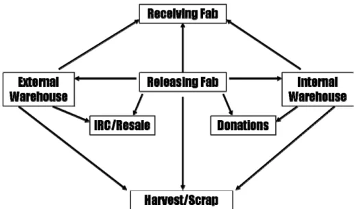
Delivery consists of the movement of capital equipment from the Intel® dock at the releasing Fab or site to its final destination at the receiving Fab or site. The final destination can be an internal or external warehouse, another Fab site, harvest, scrap, IRC12, or donations, as pictured in Figure 4.
Figure 4 - Options for Tool Delivery
Intel® maintains a few internal or Intel®-owned warehouses for temporary storage of tools until such time as the tool is needed by another Fab. External warehouses of third party logistics (3PL) providers are also used when Intel does not have the space.
Harvesting or scrapping of tools occurs when the tools are deemed unnecessary for other sites and not worth enough to sell. At those times, scrapped tools are most likely
26 involves taking parts from the tools for use in other functioning tools. Donations of the equipment are occasionally made to educational institutions for research purposes.
The number of tools received by Intel® Resale Corporation12 (IRC) has been climbing especially as Intel® makes the transition from 200mm to 300mm tools. Tools deemed of good quality and of enough net worth are sold by IRC12 to other companies or consumers who desired Fab equipment. The revenue from these sales returns to the bottom line of the originating Fab site, encouraging tool owners to closely follow the 6D Process to ensure that good quality tools are released.
The tools are also transported directly to other Fab sites for deployment, installation and use by the receiving site.
2.4.6 6D – Deployment
Deployment of the complete capital equipment at its reuse destination is the final phase in the 6D process. It is imperative that phases 1D through 5D proceed cleanly or
deployment will be delayed. If delays occur, there could be significant impact to ramp ups of production at other Fab sites. Deployment is also key to gaining acceptance at Fabs for the use of re-used tools and the 6D Program. If no delays or issues occur, plant managers would be encouraged by the savings and support the program.
6D is the closed loop process that documents and drives communications to the releasing site regarding 3D issues that impact the re-installation process. This is done formally through a Tool Transfer Survey.
27
Chapter 3: Project Survey
3.1 Motivations and Challenges for the Project
3.1.1 Objective
There were several specific project objectives. The first objective was to map the workflow and related knowledge flow of the 6D operation. The second was to address the thoroughness, accuracy, and redundancy of the information infrastructure within the present 6D business process. Third was to identify areas of inefficiencies of the tool information data-stream while considering the effects of triggering input systems supporting the internal tool allocation process to factories. The final goal was to recommend realistic solutions to information access and knowledge flow, involving changes to IT infrastructure - both short term and long term - to ensure the greater success of the 6D Program.
3.1.2 Project Motivation and Scope
The 6D program began in November 2004 upon the recognition of waste in the
manufacturing facilities and issues in Intel®’s re-use of expensive fabrication tools. In an effort to bring an end to the waste, a plan was proposed with financial and strategic justifications to create a working group to focus on improving tool re-use at Intel®.
The 6D processes and procedures crossed many organizational boundaries within Intel®, with many stakeholders, including employees and contractors who must understand and comply with those procedures. Since key documentation was scattered across many repositories, it became difficult to gain a cross-organizational view on key compliance indicators and decision factors. The technical challenges arose from the need to monitor and ensure compliance with 6D procedures and policies across the lifecycle of
equipment, facilities and materials, from initial acquisition to final disposition. All this management of compliance occurred in an extremely fast-paced, complex, continuous
28 process technology development and manufacturing environment that was constantly changing.
3.1.3 Project Challenges
The 6D project encountered several challenges that appear typical of multinational organizational structures. To begin with, multiple stakeholders and domain experts across geographic boundaries made sharing of ideas difficult. Even with numerous meetings to encourage participation from all members and ensure effective
communication, not every person could play an active role as desired by the 6D Program. In addition, the 6D Program was growing rapidly and mandated an increased pace to realize the bottom-line impact. The program’s rapid growth resulted in increased
peripheral and support team participation, helping increase awareness and support for 6D. The accelerated advancement of the 6D Program also added to the many players already involved and the complexity of the network.
With 6D’s growth, the desired increase in management support from key 6D
manufacturing sites appeared lacking. These key executives can greatly contribute to the success of 6D by ensuring that their teams fully support the 6D processes for tool
transfers. They can champion the goals of 6D and provide incentive structures to garner the needed cooperation from participating sites.
From the intern’s perspective, the main challenge for the 6D Program was the distribution of knowledge of tool information negatively impacting data mining efforts – the
information was so dispersed that collection of the data is difficult. This affected the ability to make well-informed, timely decisions and check for compliance within the program.
29
3.2 Structuring the Research
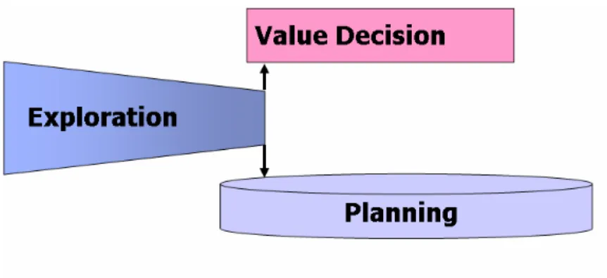
Throughout the internship, the project followed a fairly standard process of conducting research, as shown in Figure 5. An exploration phase took place in the first few months, in which the intern conducted interviews and became familiarized with the existing processes and situation.
Figure 5 - Research Structure
Once acquainted with the facts and status of the program, the value decision phase began, in which the gaps along with potential recommendations/solutions were identified. At this point, the gaps were ranked and prioritized and best strategic solutions for the highest priority gaps were recommended for implementation. Thus began the planning phase where firm development and action plans were proposed with timelines and resources required. The Methodology section below outlines in more detail the specific tasks completed as the research structure of exploration, value decision, and planning were followed.
3.2.1 Methodology Exploration:
As part of the exploration phase, determination of key stakeholders and workflow process was critical to acquiring information on existing procedures and processes. Initially, the identification of important personnel started through 6D Program members. From them, domain experts and key tool database owners were identified from which more
30 The collected information led to the creation of a comprehensive map of the existing 6D process and the inclusion of systems dealing with tool-related data. No true
improvements can be made to any process without first having a baseline of current status.
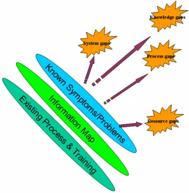
Figure 6 – Methodology for Exploration and Value Decision Phases
Value Decision:
As can be seen in Figure 6, the first two steps of “Existing Process & Training” and “Information Map” have been completed, leaving identification of “Known
Symptoms/Problems” to generate a list of gaps. Based on the gathered information and comprehensive mapping of the 6D process, steps were taken to analyze and identify known symptoms and gaps discovered during the research process by looking at cost, time, and resource avoidances. The gaps were classified into meaningful categories such as System-Related, Knowledge-Related, Process-Related, and Resource-Related Gaps. Categorization of the gaps aided in understanding the issues from a higher, system level, as opposed to paying too much attention to the smaller details. It also gave credence to a more structured approach of looking at the system. Comprehension of the gaps allowed
31 for recommendations to be made to address the identified gaps with data on costs and ROI.
Planning:
Finally, the planning phases involved development of action plans, targets, and
measurement processes to ensure compliance and achievement of goals. The majority of research concentrated on the Fabrication/Sort manufacturing business since it represented a larger percentage of the business, in terms of quantity and finances. Only at the end did the intern look at how the recommendations could be transferred to other businesses such as Assembly/Test manufacturing.
3.2.2 Domains Experts & Key 6D Personnel
Interviews and face-to-face discussions were held with many domain experts in the business process as well as in the information-systems and database domains. Every domain and information system expert interviewed made significant contributions to the project and to this thesis. It was extremely helpful and insightful speaking with all of them as they explained the intricate connections between various information systems and how those systems related to the 6D Program. Also, each person spoken to always knew one or more other people or information systems the previous person was not aware of. In this manner13, numerous interviews were conducted and large amounts of data were gathered dealing with the 6D Program and the tool-related information systems or databases.
Over 50 people were interviewed with regards to the 6D Program and to any tool-related systems. Most of the interviewees could be classified into two categories: 6D Program experts and domain experts. 6D Program experts either knew a great deal about the 6D Program in general or knew a great deal about a specific aspect of the 6D Program. Those with high-level, generalized knowledge were usually part of the 6D Focus Group, made up of the program managers and crucial members of the 6D team. Those with specific knowledge on certain aspects of the 6D program were usually role players from
32 the 6D Working Group who held very explicit jobs in Fabs throughout the world.
Finally, the domain experts were usually the administrators or frequent users of the tool information systems. They truly understand all aspects of the system and its
interdependencies with other information systems.
3.2.3 Information Systems for Tools
Almost 25 information systems or databases related to the 6D Program or manufacturing tools were identified in the course of the research. This was almost 5x the number of systems14 believed to have been important to the 6D program before the research began. The systems were subdivided into two main categories: Main Systems and Support Systems.
The Main Systems were those that played an integral role in maintaining Intel®’s records and were vital in the 6D process. The Support Systems also played an integral role to Intel® and the 6D Program, but weren’t always prioritized in relation to 6D. The systems contained some aspect of information pertaining to manufacturing tools. All of this information may not be a major part of the actual tool transfer, but in the end will help any receiving site or customer utilize the tool more efficiently. In fact, much of the information from Support Systems significantly assists IRC12 in making quick sales of the used equipment and for a higher price.
Eventually, all of the Main and Support Systems were linked with the 6D work flow resulting in a comprehensive mapping of the 6D Program.
3.3 Implementation Frameworks for Project Success
Stakeholder maps and three lenses analysis are tools useful in analyzing organizations, such as the 6D Program, to understand the inter-relationships and obstacles to success. They can play an important role to comprehending why certain issues exist and how they might be resolved. In the case of a three lenses15 analysis, the majority of these issues
33 can be separated into three distinct categories as they relate to strategic organizational design, politics, and culture. Each lens will be analyzed in depth and explained.
3.3.1 Stakeholder analysis
A stakeholder analysis and map, such as the one shown in Figure 7, is a network diagram of the relationships between all of the stakeholders. It aids in understanding the
stakeholders involved in and affected by the project and what their interests were. More specifically, the stakeholder map shows the relationship between each of the
stakeholders, what each stood to gain or lose from the project, and how willing and/or able they were to support the project. This gave much insight into how to pursue the research project and who the role players were. Ultimately, stakeholder mappings were a helpful tool in understanding the connections to the 6D Program and only served as an aid and not the answer to the project.
34 3.3.2 Strategic Lens
The strategic lens theory16 of organizational analysis states that goals are achievable by grouping and linking units in order to accomplish tasks. This rational, analytical
approach assumes that with the right plan, information flow, and alignment of incentives, the organization can achieve goals in an efficient manner.
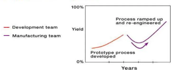
In the 70’s and 80’s, Intel® Corporation utilized the traditional model for process development and technology transfer. The development team handed off the prototype process to the manufacturing site at a low production level with a handshake agreement that could last several months. When the handshake agreement was complete, the development group then proceeded to develop the next process technology for high volume manufacturing (HVM). The result was that as technologies grew more complex, the yield immediately after transfer took a “U-turn” and up to several years were spent recovering to the normal yield learning rate.17 The results of such a development process are shown in Figure 817 below.
Figure 8 – “U-Turn” Result from Tradition Development Process17
Ultimately, the less than effective results of traditional process development led to a change of strategy for Intel® – A Copy Exactly18 (CE) concept was developed to minimize impacts to yield upon transfer to new production sites. In such as process, a Virtual Factory (VF) was created where several factories were designed to run exactly the same process steps in exactly the same manner. The Fabs in a particular VF had the goal of being identical in every respect except where there were hard barriers such as
35 transfer, all Fabs copied what existed in the development Fab. During development, the Ramp Program Manager would determine what the development Fab would copy from the previous technology. After the start of ramp, all Fabs would copy best known roadmap improvements irrespective of their source. The factory manager that wishes to deviate from CE carried the burden of justification to a Steering Committee that oversaw CE. The CE Steering Committee reviewed, approved, and rejected the recommended improvements for the entire VF.
This new strategy of Copy Exactly became the basis for all of Intel®’s organization from a manufacturing and operations standpoint. Yet even though CE permeated Intel® and everyone knew about it, the practice didn’t really spread beyond the manufacturing sites, more specifically, the actual fabrication process of the chips. Intel®’s various groups, including resale, certification, manuals, warehouse, docking, etc. across different
manufacturing sites, sometimes created and utilized their own processes, procedures, and information systems. Many times this was done without communicating with their peer groups or even the same group at another site who utilized the same information or performed the same functions.
For example, Intel® utilized BKM (Best Known Methods) or best practices, but groups sometimes started with a BKM and then modified the BKM to fit their specific needs, such as taking the requirements of an information system, adding more features, and finding a brand new system that was more applicable for that specific group’s needs. In theory, the modified BKM would be acceptable and there was always continuous improvement on the BKM. In practice, this resulted in each group doing similar tasks almost the same, but different enough that the created systems couldn’t work together.
The 6D Program highlighted more clearly the disparities in various groups’ knowledge information systems and procedures due to its innate cross-functional nature. The project crossed the boundaries of the 6D Working Group into many other areas of Intel® that don’t deal with 6D such as tool manuals, training, performance, tool and technician certifications, etc. This made the research both easier and more difficult. It was more
36 straightforward in that there were no pre-conceptions about the 6D Program in the
external groups and those groups were usually more than willing to help. It was more difficult in that those groups sometimes didn’t fully understand the importance of the 6D Program to Intel®’s bottom line and thus time had to be spent educating them on the program’s significance. For the most part, having people associated with 6D in numerous organizations throughout Intel® helped in the progression of the project – as more people of different domain expertise became familiar with and supported 6D, the program evolved and improved with the addition of distinctive ideas and enhancements.
The intern belonged to a group known as Knowledge Management (KM). This group endeavored to help cross the organizational divides and create true cross-functional, common processes. Due to KM’s overarching mission and current business
relationships, the intern had access to several internal contacts that might not have been associated with the 6D Program. This helped in bringing other domain experts into the 6D fold.
3.3.3 Political Lens
The political lens19 views the organization as composed of multiple stakeholders who contribute to the organization and depend on its success, but have different interests and goals and bring different amounts of influence to bear. The organization, such as the 6D Program, must acknowledge the inherent differences in interests and goals. 6D must better align the various interests and goals to produce joint gains, build coalitions to change distribution of power, negotiate solutions or outcomes, and resolve conflicts.
A core group of participants in the 6D program had and continue to have aligned
interests. Of course, each party has its own opinions on how things are done, but at least weekly meetings are held to discuss the best methods and there is clear leadership
established. An interesting view of 6D came to light during the course of the internship – 6D is fairly well established in FSM (Fab Sort Manufacturing), but remains in the infancy stage for AT (Assembly Test). It is interesting to see where power resides in either
37 organization and who can get more accomplished. In FSM, senior people from business operations and corporate service construction are in charge of the 6D program. Both are groups with wide, lateral influences and connections to many other organizations. This has allowed them to call in many of their contacts who might not be so adverse to the 6D concept. On the other hand, in AT, the 6D management has resided in the hands of engineering, more specifically junior members. Not much progress had been made to advocate 6D in AT until the disparities between FSM and AT were understood. Changes have been made in AT’s 6D Program to fully utilize all groups’ influences and promote the 6D mantra. More senior and more knowledgeable people have been placed on the 6D program from the different factory sites. This allowed these well respected individuals to garner more support from their organizations and sites. Several months after the end of the internship, the model in AT is now almost identical to FSM. Many of the core organizations have simply crossed over to AT and the FSM Business Operations counterpart in ATM along with Corporate services own the 6D Program in AT.
More specifically, with regards to the details of this thesis research, implementation of the thesis recommendations will not be simple. There are differing groups and differing owners for each tool information system. Each group wants total control of their
information as it pertains to their business function. Sympathetic individuals will need to be found in each group to help convince their organizations of the overall effectiveness of the recommendations. Intel®’s individual performance rating process plays a major role in the employees’ behaviors. Individuals are only judged within the peer group and incentives are aligned as such. So for an individual to receive rewards and grow in their careers, he must do things important to the peer group and not necessarily important for the company.
3.3.4 Cultural Lens
The cultural lens20 believes people take action on the basis of their situations and on the basis of what their situations mean to them. It focuses first and foremost on the meanings people assign to their respective work experiences. The key is the symbol (values,
38 languages, beliefs, founding legends, social norms, myths, rituals), and what these
symbols mean to different people in an organization.
It is difficult to talk about Intel® without a good understanding of its very unique culture; even the strategic and political discussions involve some cultural aspects. Intel®’s culture permeates all decisions made, how people behave and work, and how work gets
accomplished. Intel® is very data oriented as can be seen by its dedicated use of Excel and PowerPoint. Most things are shown in PowerPoint even if it may not the best method of communication. Intel® is such a data driven company that the presentations are inundated with information. The information is useful, but too much information might cause the intended audience to lose focus on the big picture – the 6D Program saves Intel® money!
It would seem also that Intel® employees have become telecommunication experts in their use of conference calls and net meetings. The virtual meetings might allow members to not fully participate due to the out of sight nature of the meeting. Few meetings are conducted face to face any longer due to the wide extent of the company. Intel® is a global company, and they have excellently figured out how to work as a global team. But a reduction in personal interactions makes it difficult to create true team camaraderie and dynamics towards one goal.
It appears that the large number of Intel® employees, located in several geographies, may have caused what appears to be the creation of multiple “smaller companies” within one massive organization. There are numerous business units and organizations each with their specific goals and objectives. The 6D Program goes against the grain of Intel® culture in that it tries to span the “smaller companies” and do what is best for Intel®. Ultimately, the 6D Program uses the data-oriented aspect of Intel® to convince the “smaller companies” within Intel® that the program is worthwhile and therefore any projects dealing with 6D are also essential to Intel®, the “larger” corporation.
39 Figure 921 shows an excellent pictorial of what tends to occurs in fast-paced multinational organizations. Intel® faces the typical psychological inertia found in organizations. It endeavors to and succeeds in understanding every minute aspect of the problem and the solution. Intel® will dig as far as it must to not leave a stone unturned when looking for root cause and solution. It always solves the initial issue as well as any related aspects.
Figure 9 – One Aspect of Fast-Paced Organizations21
But as the picture states, in the process of understanding the problem, organizations might lose sight of anything else not dealing with their specific problem including the overall picture. Such situations could become factors in further compounding the problems for organizations where groups act like “small companies.” There are several layers between the CEO and the individual contributor, making it difficult to
communicate macro-level objectives and strategies. De-layering or minimizing the management structure between the chief executive officer and the individual contributor can achieve “faster decision making, quicker awareness of market needs and competitor moves, and lower costs.”22
40
Chapter 4: Research Findings
Extensive time spent in knowledge and data gathering proved fruitful in discovering the impact of tool information systems upon the 6D process and the wide ranging effect of the 6D Program upon those same information systems.
4.1 6D Map with Information Systems
A comprehensive map of the 6D process including the infrastructure of the tool
information data-stream was constructed. This map included the databases and systems that were mainly used by the 6D team and other support/peripheral systems that would be used by the receiving factory site and/or the IRC12 team.
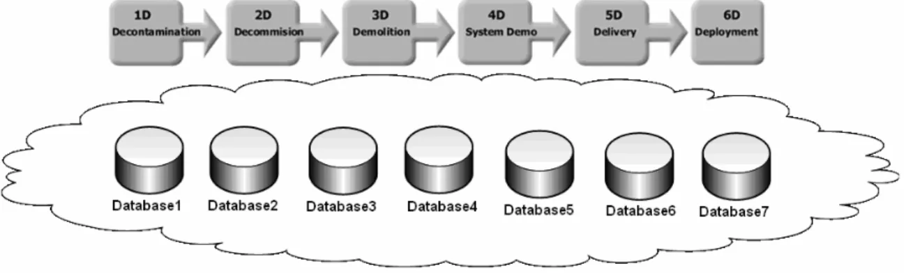
Figure 10 - High Level 6D Process with Information
Figure 10 shows the process map from an extremely high level. The information system or database (DB) names are masked for confidentiality purposes. In general, some systems are used throughout the 6D process while other systems are only utilized during certain time periods. For example, the ERP System, Intel®’s system of record, was used in 1D, 2D, 3D, 5D, and 6D to ensure accurate documentation of equipment status and location, but the warehouse inventory management system was only employed during 5D – Delivery/Storage. The all-inclusive 6D work and knowledge flow map showed
41 As previously described, the information systems identified could be classified into “Main Systems” and “Support Systems”. Main Systems performed different functions such as scheduling installation and demolition of tools, tracking and coordinating tools as they were transferred, and keeping track of inventories within the warehouses. A central information storage site kept all pertinent documents available for access by members of the 6D Program. Anyone could upload and download files related to 6D to this site. One of the fundamental systems created by and utilized only for the 6D Program was the Tool Transfer Tracker (TTT)23. This system could track a tool being transferred from site to site as it followed the 6D process and ensure compliance at specific checkpoints. Most Main Systems traversed and were highly utilized in the 6D work flow.
On the other hand, the Support Systems usually only occurred in one or two of the “D’s” in the work flow, typically in 6D. The Support Systems contained some aspect of information pertaining to manufacturing tools such as performance, preventative maintenance schedules, manufacturing efficiency, manuals, specifications, etc.
Technician certification procedures for each tool were also available for each Fab site. Many of the systems directly touched on a tool’s actual transfer status such as shipping memos, forms to move capital equipment, dock receiving, etc. Though Support Systems didn’t play as key a role to the tool transfer process, they contained very relevant
information that would aid in successful transfer, installation, and qualification of the tool in its final disposition.
Appendix A - 6D Work/Knowledge Flow Mapshows a detailed mapping of 6D work and knowledge flow. A more detailed work flow shows some of the specific tasks completed within each “D” along the 6D process. Beneath the work flow is the knowledge flow of tool information. Each “D” is highlighted in a specific color to make each step more distinctive and to show when each information system is utilized as it crosses the 6D process. As can be seen in Figure 20, the number of information systems used in 6D has almost doubled the number used in 5D. Most represent the numerous peripheral systems that are highly valued by the receiving Fab site in ensuring excellent, fully-functional equipment.
42
4.2 Overview of Gaps Identified
In the course of the research, several issues or gaps were identified in relation to the knowledge flow amongst the various information systems as they pertained to the 6D process. These gaps were classified into four main categories:
• System-Related Gaps - topics concerning the diverse use of information systems by different Fab sites and the specific interactions linking the various information systems.
• Knowledge-Related Gaps – topics concerning the lack of knowledge coherency and the sharing of knowledge across Fab sites and information systems.
• Process-Related Gaps – topics concerning the standardization of processes and reporting features.
• Resource-Related Gaps – topics concerning the people resources utilizing the 6D process and incentive alignment.
The scenario below quite aptly describes how all four gap classifications can occur quite easily in a highly complex environment – 6D Program’s tool demo procedures. The scenario does not describe a specific situation that has occurred in the 6D work flow, but instead shows a high level representation of some issues that might occur.
The cloud in Figure 11 shows several different pieces of knowledge or information available within a company. This knowledge could be several things such as
specifications, preventative maintenance checklists, databases, equipment manuals, or training materials, etc. An engineer has a specific subset of knowledge about different products and processes, eg. Product “A” and Product “B”.
43 Figure 11 - Gap Identification Scenario - Phase 1
A second engineer has another subset of knowledge about other products and processes (Figure 12). Quite often, both engineers share common knowledge about certain topics since there are many highly leveraged processes throughout the company.
44 In many situations, those engineers will understand and utilize the same processes “2” in different manners causing inefficiencies by having inconsistent content – system-related, process-related, and resource-related gaps (Figure 13).
Figure 13 - Gap Identification Scenario - Phase 3
A training developer needs to develop training materials and writes a slightly varied version of the same process “2” (Figure 14). Now there are multiple versions of the same process with all of them possibly out of sync and potentially causing quality issues – knowledge-related gaps and leaving a very confused end user.
45 Figure 14 - Gap Identification Scenario - Phase 4
This is just a simple scenario of how quickly disparate knowledge can cause quality issues in processes and amongst users, touching on all four areas of systems, knowledge, process, and resources. Gaps in each of these four areas are discussed next.
4.3 System-Related Gaps
Ultimately, to avoid many system-related gaps, updates to the ERP System should occur on a real time basis and more information could be added as to the status of all tools. But to track tools more accurately and have more information in the ERP System would involve a long development time and “throw-away code” due to planned future
deployment of the next generation of the ERP System. There will still need to be other Main Systems for scheduling tool installs and tool transfers, but the ERP System could serve as the key system linking all other systems. Thus current systems must be
implicitly linked and updated constantly, or gaps in information will cause quality issues. For example, inaccurate tracking of current inventory might result in suboptimal reuse and possible over-purchase of equipment.
46 Other system-related gaps such as the same information systems being used differently at the different sites also occurred. Scheduling software for tool demolition and installs were used in different manners from Fab site to Fab site because users tracked distinct milestones. In the same vein, benchmarking and preventative maintenance scheduling of tools were not centralized in VF, so there was no easy accessibility to all the information. Warehouses also utilized different systems to track inventory as opposed to using one system for the entire company. So different technical support groups were necessary for each system, and all other systems that interfaced to the warehouse databases needed to account for the dissimilarities. In another case, training materials for tool certifications were site specific instead of trying to share information across the VF and saving time and effort. Many of the systems were handled on a site to site basis, when resources could have been consolidated and information could have been more easily accessible.
Another system-related gap not associated with tool information systems, but with the 6D process, was the fact that demolition was not the first step of install/qualification of the tool at the receiving site. The receiving site personnel did not have to participate physically in the demo. The 6D Program only needs the receiving site personnel to be more engaged in understanding the 2D checklist, what was in the TTT template, what would be audited, what performance data would be provided, etc. Internal company organizational hierarchy, politics, and the structured expansion of the 6D Program complicate the inclusion of IQ (Install/Qualification) in the 6D process. If the receiving site tool owners believed demolition or even decontamination/decommission were the first steps in the IQ process, then they would play a more active role in the tool transfer process. As their objective was to have a quick ramp up and qualification of the tool they were receiving, the tool owners had strong incentives to ensure the tool moved smoothly through the 6D process. By refocusing on the 6D, receiving sites are engaging in the process by reviewing checklists, templates, data collection, and methods that will be used during the demolition of the tool. This will improve the IQ linkage to demolition over time.
47
4.4 Knowledge-Related Gaps
Knowledge-related gaps deal with the lack of knowledge coherency and the sharing of knowledge across Fab sites and information systems. Linked closely with system-related gaps, knowledge-related gaps resulted from the site specific nature of most information systems. Without the availability of a central location for all the tool information, easy access to the knowledge can’t be obtained and it was difficult to check for consistency of data across all the databases. Inconsistencies abounded between the various information systems in terms of specific field names to contradicting information. For example, one system might claim a tool was in Location A while a different system stated the tool was in Location B. Deciding on which system superseded the other can be a complicated matter and even more importantly, which system was correct is of the utmost importance.
Another knowledge gap that contributed to higher level issues was the lack of a
centralized location for lessons learned or BKM’s. Lessons were not easily shared when users could not access one location for the information.
4.5 Process-Related Gaps
Process-related gaps deal with the standardization of processes and reporting features. While there exists a high level standard operating procedure (SOP) for the 6D process, more standardized processes are necessary. Several of the systems could use better processes on how information is entered and stored. This would allow easier linkages between the various information systems. As it stands, most of the information is entered into systems at the discretion of the system administrator and, as such, an irregular user of the system might not understand the details of the keyed data. This does not apply to every system related to tool information. In fact, the TTT system contains very specific processes on input of information and is standardized such that any user can understand the tool information.
More flexible reporting features and alerts are necessary. Systems pertaining to data storage, warehouse inventory management, and scheduling need better reporting