HAL Id: hal-01183173
https://hal.archives-ouvertes.fr/hal-01183173
Submitted on 6 Aug 2015
HAL is a multi-disciplinary open access
archive for the deposit and dissemination of
sci-entific research documents, whether they are
pub-lished or not. The documents may come from
teaching and research institutions in France or
abroad, or from public or private research centers.
L’archive ouverte pluridisciplinaire HAL, est
destinée au dépôt et à la diffusion de documents
scientifiques de niveau recherche, publiés ou non,
émanant des établissements d’enseignement et de
recherche français ou étrangers, des laboratoires
publics ou privés.
Variability of a Bolted Assembly Through an
Experimental Modal Analysis
Sami Daouk, François Louf, Christophe Cluzel, Olivier Dorival, Laurent
Champaney
To cite this version:
Sami Daouk, François Louf, Christophe Cluzel, Olivier Dorival, Laurent Champaney. Variability of
a Bolted Assembly Through an Experimental Modal Analysis. IMAC XXXIII - A Conference and
Exposition on Structural Dynamics, Feb 2015, Orlando, United States.
�10.1007/978-3-319-15224-0_18�. �hal-01183173�
Variability of a bolted assembly through an experimental modal analysis
Sami Daouk
1, Franc¸ois Louf
1, Christophe Cluzel
1,2, Olivier Dorival
3, Laurent Champaney
11
LMT-Cachan, ENS-Cachan/CNRS/Pres UniverSud Paris,
61, avenue du Pr´esident Wilson, 94230 Cachan Cedex, France
2
IUT-SGM, rue du P`ere Jarlan, 91025 Evry, France
3
Universit´e de Toulouse, Institut Cl´ement Ader (ICA); INSA, UPS, Mines Albi, ISAE,
135 av. de Rangueil, 31077 Toulouse Cedex, France
ABSTRACT
Industrial structures are mainly assemblies with complex geometries and non-linear characteristics. Friction and joint preload added to fabrication imperfections lead to a substantial gap between numerical models and real structures. In order to de-velop accurate generic models, it is then necessary to quantify the behavior variability, especially the one related to the joint conditions. The first part of this paper describes the iterative sizing procedure of an academic assembly which characteristics may vary depending on several input variables (e.g value of the bolt torque, number and position of preloaded bolts, etc.). The properties of the bolted joint were optimized in order to satisfy a set of conditions in terms of tangential slipping, normal displacement and maximum stress level. The second part concerns the experimental modal analysis of the assembly. The main purpose is to characterize the relationship that exists between the input variables and the measured eigenfrequencies and modal damping of the assembly.
KEYWORDS
Experimental variability, Bolted joints, Uncertainty quantification, Modal analysis, Modal damping 1 INTRODUCTION
Mechanical systems are commonly analyzed assuming that the mathematical models are deterministic and the input data is precisely defined. Nevertheless, in most cases, parameters of the mathematical-mechanical model linked to geometry, boundary conditions and material properties can neither be identified nor modeled accurately. The need to address data uncertainties is now clearly recognized, and over the past decades there has been a growing interest in stochastic modeling and application of probabilistic numerical methods [1, 2].
It is our will to have a better understanding of experimental variability, especially in the case of bolted assemblies. In fact, even though the sources of uncertainties can be well identified, the characterization of their influence on the dynamic behavior is still not well known. The main objective of this study is then to quantify the influence of joint parameters on the dynamic response of a bolted joint. Some relevant parameters to be considered are the value of the bolt preload, the number and position of preloaded bolts and lubrification conditions. To achieve that, it is necessary to have a bolted joint with binding conditions that can be easily varied. It is clear that a low level of effort in the joint, the variation of the parameters mentioned earlier will not cause any significant change in the dynamic response of the connection. However, in case of heavy loads, sliding in the joint may appear in different areas of contact, i.e. the contact between the parts and the contact between bolts and parts. This sliding will be source of energy dissipation and thus contribute to a variation of eigenfrequencies and modal damping. However the application of high stress levels in dynamic is not possible with an experimental material of reasonable size. One interesting solution is to take advantage of the dynamic load amplification at resonance and build parts to store elastic and kinetic energy and raise the stress levels in the joint. Eccentric masses (kinetic energy) were added and linked to the bolted joint of interest by long beams (elastic energy). The conversion of kinetic energy into elastic energy from the masses to the beams enables the transfer of the desired efforts to the central bolted joint.
The first part of this paper describes the iterative sizing procedure of a bolted assembly which properties were optimized in order to satisfy a set of conditions in terms of sliding and maximum stress level. The second part presents the experimental procedure and the first results of an experimental modal analysis of the assembly. The purpose is to find the relationship that exists between the input variables and the eigenfrequencies and modal damping of the assembly.
2 SIZING PROCEDURE
2.1 Estimation of eigenfrequencies and frequency responses
The first step in the sizing procedure of the bolted joint is to estimate the first eigenfrequencies of the assembly in free-free vibrations, in particular the ones associated with bending modes. Considering a structure with cylindrical symmetry, there will only be symmetric or anti-symmetric modes. The exact values of the eigenfrequencies can be found, but in order to avoid time-consuming calculations, approximations were made. For this, the Rayleigh quotient method is used assuming a simple polynomial form of the eigenmode that will lead to an overestimation of the exact desired eigenfrequency.
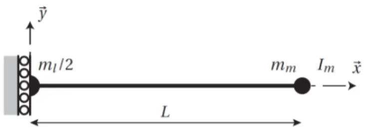
For instance, figure 1 shows the simplified model associated to the first eigenmode, i.e. a symmetric bending mode. The experimental modal analysis will be carried out with free-free boundary conditions, so two rigid body modes are possible in the case of a planar study: a transverse translating movement and a rotation about the axis out of plane. If we study a symmetric mode, there can not be any rotation, which explains the choice of the boundary conditions at x = 0. The remaining degree of freedom is important: if eliminated, the center of gravity of the deformed configuration will not be the same as that of the non-deformed configuration, which contradicts an important property of structures vibrating in free-free conditions.
Figure 1: Model used to estimate the first eigenmode (symmetric bending mode)
Let Vs,1(x) be a kinematically admissible displacement field describing the first symmetric bending mode of the structure.
Several forms of the field Vs,1(x) were considered, such as the sum of a rigid translating mode and a mode deforming the
structure such as Vs,1(x) = a + x2or Vs,1(x) = a +Lx22−x
3
6. For each form, we write the Rayleigh quotient as:
R(Vs,1) = � L 0 EI(V �� s,1(x))2dx � L 0 ρS(Vs,1(x)) 2dx +1 2ml(Vs,1(0))2+mm(Vs,1(L))2+Im(Vs,1� (L))2 (1)
where E,ρ, L, S and I are respectively the Young’s modulus, the density, the length, the section and the second moment of
area of the beam; mlis the mass of the central bolted joint of interest; mmis the mass of an eccentric mass and Imits moment
of inertia about an axis passing through its center and orthogonal the x-axis.
Then we search for the coefficient a that minimises the Rayleigh quotient and then the corresponding eigenfrequency. The latter is compared the the eigenfrequency of a numerical beam model that has the same geometry, masses, inertia and material
properties. That’s how we can find the best approximate displacement field Vs,1(x) describing the first eigenmode. And the
same procedure is followed for the other eigenmodes of interest.
Once the different eigenmodes of interest are known, it is possible to estimate the frequency response of the structure at a given forced excitation which maximum is set at 1000 N in our study case (maximum force level of the shaker used). In particular, we seek to estimate the oscillation amplitude at resonance, assuming a low modal damping, but obviously not zero. When considering the forced vibrations problem in the case of a viscoelastic material with low damping, the magnitude of the
amplitude qi(ωi)associated to the mode i writes:
|qi(ωi)| =FUωi(x0)
iCi (2)
whereωiis the angular eigenfrequency of mode i, F is the magnitude of a punctual harmonic load applied at the point x = x0
atωi, Ui(x) is the shape of the eigenmode i (that was approximated previously using the Rayleigh quotient method) and Ciis
the viscous damping coefficient. This relationship is obviously independent of the type of problem (bending, tension, torsion) so it will be possible to find the amplitude at resonance in all cases of interest.
For instance, in the case of the first symmetric bending mode of the structure, we find the magnitude of q(ωs,1)as:
|q(ωs,1)| =8Im 4Fml+5FρSL
where the modal damping ratioζ has been introduced.
Then the bending moment in the beam around the z-axis at resonance is:
Mz,s,1(x) = |q(ωs,1)|Vs,1��(x) = −8ImI(L − x)E(8Fmm+3FρSL)
lEζ + 16ImmEζ + 16ILSEζρ (4)
which leads to the shear force
Qs,1(x) = |q(ωs,1)|Vs,1���(x) = −8Im IE(8Fmm+3FρSL)
lEζ + 16ImmEζ + 16ILSEζρ (5)
and the bending normal stress in the beam can be found as: σs,1(x) =Mz,s,1(x)
I D
2 =−
D(L − x)E(8Fmm+3FρSL)
2(8ImlEζ + 16ImmEζ + 16ILSEζρ) (6)
In our calculations, a modal damping ratioζ = 0.2 % was considered for all studied modes. This value is relatively low and
leads to a higher estimation of the amplitudes and stress levels, but then the sizing procedure remains conservative. 2.2 Optimization of the design of the bolted joint
After estimating the eigenfrequencies and calculating the stress levels in the model, we proceeded to the optimization of the design of the bolted joint regarding the moments and stresses generated in the beams at resonance. The preload range that was considered goes from 20 % to 80 % of the yield strength of the screws.
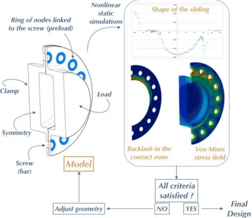
Figure 2: Optimization procedure of the design of the bolted joint In particular, it is necessary that the joint resists but also works in a significant way at resonance:
• in the preload range considered, we wish to have local backlash in the contact zone between the parts, in the order of 0.05 mm for an average preload ;
• in the preload range considered, we wish to have local sliding between the parts, in the order of 0.005 mm for an average preload.
The second step of the sizing procedure is then to perform nonlinear static simulations to visualize these effects, and increase them, if necessary, by changing the geometry. These calculations are performed for a given geometry of the parts of the bolted joint and for a precise eigenmode. The value of the load is given by the previous step of the sizing procedure. For instance, in the case of the first symmetric bending eigenmode, the load to apply is the bending moment and shear force of relations (4) and (5). A Coulomb friction model without kinetic effects was considered with a coefficient of friction of 0.2 (steel-steel). In addition to the values of slipping and backlash in the contact zone, it is essential to check the stress levels in both parts, which may not exceed 400 MPa in order to remain in the elastic range and avoid damaging the parts.
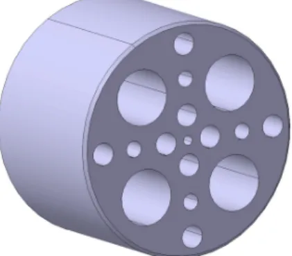
As shown in figure 2, the last step is the adjustment of the characteristics of the parts in order to reach the desired siding, backlash and stress levels, mainly for the first symmetric and anti-symmetric bending eigenmodes. In fact, these modes will have the most significant effect on the bolted joint. For that, the stiffness, mass and inertia of the parts of the joint are modified while minimizing the dissipation in the other joints of the assembly, namely between beams and masses, and between parts of the joint and beams. Figure 3 presents the final design of the assembly resulting from the sizing procedure, where 16 bolts can be loaded in the central joint of interest. The assembly has been designed so that the eigenfrequencies are separated and the first ones associated to bending modes are less than 1 kHz.
Figure 3: Final design of the assembly
The evaluation of the energy dissipated only in the bolted joint can be done by carrying out differential identifications. That’s why a reference part shown in figure 4 was designed as a rigid part with a simple geometry of the same length as the bolted joint under study. It also is mounted to the beams in a similar way and has a equal bending and torsion moments of inertia. Its mass may vary by filling the holes or not in order to be consider the case of 8, 12 or 16 loaded bolts.
Figure 4: Reference part built to evaluate the energy dissipated only in the bolted joint
In order to evaluate the dissipation in the bolted joint of interest, the same experiments are carried out on the assembly with the joint and the assembly with the reference part. When applying the same energy through the shaker, for a given mode, the difference in the elastic energy of the beams between both assemblies leads to the energy dissipated in the central bolted joint.
3 EVALUATION OF MODAL DAMPING
When the structure is lightly damped, its distribution is almost always not well known, and it is usually necessary to make an assumption about the distribution. A first measure considers that damping is constant depending on the level of vibrations, which makes it precise in the case of a low loading level only. That is mainly due to the fact that experimental control is
automatic and vibrating at the natural frequency is too risky to inject a high load. This approach considers the frequencies fi,1
and fi,2of the bandwidth at -3dB of the maximum of the transfer function around the resonant frequency fi. The corresponding
damping ratioζiis the given by the relation:
ζi= f22 f− f1
i (7)
Another measure is the Specific Damping Capacityψ that intends to measure damping for a given deformed shape such as a
modal shape. It is expressed as a ratio of the energy dissipated per cycle and the elastic energy (or energy stored) per cycle:
ψi=W
i i −Wie
We
i (8)
where the injected energy Wican be calculated by summing the power injected in the assembly per cycle as:
Wi=� T 0 − →F .−→v dt =� T 0 − →F .−→du (9) −
→F being the effort applied through the shaker and −→v the velocity of vibrations,
and the elastic energy Wecan be calculated on both beams as:
We=1 2 � Ω σ ε dΩ (10) =2� L 0 Mi2
2 EI dx in the case of bending mode i (11)
When using this energy ratio to evaluate damping, no assumption is made about the relationship between damping and the level of vibrations. This measure leads then to a better characterization of modal damping for any loading level in the joint. The Specific Damping Capacity can be related to the modal damping ratio via the relation:
ψi=4π� ζi
1 − ζ2
i
(12)
4 EXPERIMENTAL PROCEDURE
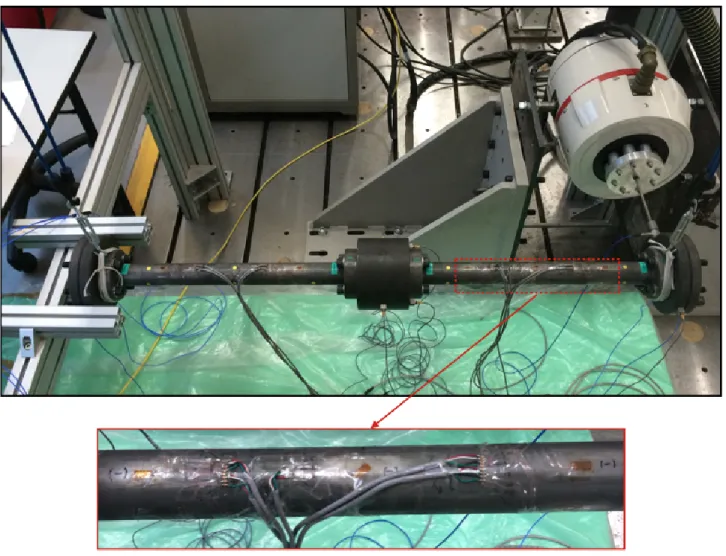
Several experimental tools are needed in order to measure finely the quantities of interest. Uniaxial and triaxial accelerometers were used to measure the natural frequencies of the assembly. The use of accelerometers is also necessary in order to measure the energy applied through the shaker. Strain gages are another important tool that was used. To evaluate the magnitude of the efforts in the bolted joint, 20 strain gages were glued on the beams as shown in figure 5. They were arranged in 8 half bridges (4 in the horizontal plane and 4 in the vertical plane) to measure bending, and one full bridge to measure torsion. The evaluation of the magnitude strain in the beams leads to the knowledge of the elastic energy of the assembly (mainly stored in the beams).
The experimental procedure is structured into two parts. First, it is necessary to carry out a modal analysis of the reference assembly. This will validate that all manipulations and tests that will be carried out on using the bolted joint are without risk on the joint. In fact, as the vibration at a natural frequency will result in a dynamic amplification whose magnitude is unknown, an upper bound of the amplitude of the loads in the joint is needed in order to keep the strain in the elastic range. A second objective of studying the reference assembly is to have the reference information necessary for the differential identifications of the energy dissipated in the bolted joint.
The analysis of the reference assembly includes three steps:
• The first step is to determine the eigenfrequencies and eigenmodes under 1 kHz. These quantities are measured for a low loading level firstly by using a hammer and then through a white noise applied by the shaker
• The second step is to evaluate modal damping, by using the methods presented in section 3. The results of all methods should be the same in the case of low loads.
Figure 5: The reference assembly analyzed in free-free vibrations
Figure 6: The bolted joint under study
• The last step is the measurement of the variation of eigenfrequencies and modal damping depending on the applied load. The second part of the experimental procedure is the study of the dynamic behavior of the bolted joint. At first, we carry out
the same tests performed on the reference assembly. This step is essential to the success of the differential analysis which includes two aspects:
• the eigenfrequency variation: it could be either linked to the damping variation or to the stiffness variation resulting from the deformation of the thin support plates of the joint (thickness of 6 mm), as shown on 6.
• the damping variation: it is evaluated by considering the energy variation between both assemblies (the one with the bolted joint and the reference assembly).
Finally, the modification of joint conditions (e.g value of the joint preload, number and position of preloaded bolts, ...) leads to the characterization of their influence on the dynamic behavior of the joint.
5 FIRST RESULTS
The first experimental results presented in figure 7 show the eigenfrequencies of the reference assembly under 2kHz. The values are smaller than the ones of the numerical model, but without a major gap.
0 256 512 768 1024 1280 1536 1792 2048 10−4 10−3 10−2 10−1 100 Frequency (Hz) Amplitude (g/N)
Figure 7: The frequency response function of the reference assembly showing the eigenfrequencies under 2 kHz The first work was focused on the first eigenfrequency, which is associated to a symmetric bending mode. We noticed that the value of the eigenfrequency decreases when the load is increased. It is hoped that, as the bolt torque and the number of preloaded bolts increase, the contact becomes more rigid, which leads to an increase of the measured natural frequencies. 6 CONCLUSIONS AND FUTURE WORK
The first part of the paper described the iterative sizing procedure of a bolted assembly where the joint conditions may vary. The properties of the bolted joint were optimized in order to satisfy a set of conditions in terms of tangential slipping, backlash and maximum stress level. The second part described the methods used to evaluate modal damping experimentally and presented the experimental procedure. The frequency response function of the reference assembly shows that the eigenfrequencies are coherent with the numerical model. The future work is firstly to analyze the variation of eigenfrequencies and modal damping. Then, the modal analysis of assembly with the bolted joint will be performed. The purpose is to characterize the relationship that exists between the different joint conditions and the measured eigenfrequencies and modal damping of the assembly. In the framework of the SICODYN Project [3, 4], initiated in 2012 and carried out till 2015, the experimental modal analysis will be extended to the case of a booster pump studied within its industrial environment. That would lead to a better under-standing of experimental variability and then to an assessment of the ability of parametric and non-parametric probabilistic numerical methods to consider and propagate uncertainties in bolted assemblies.
7 ACKNOWLEDGEMENTS
This work has been carried out in the context of the FUI 2012-2015 SICODYN Project (SImulations credibility via test-analysis COrrelation and uncertainty quantification in structural DYNamics). The authors would like to gratefully acknowledge the support of the FUI (Fonds Unique Interminist´eriel).
REFERENCES
[1] Matthies, H. G., Brenner, C. E., Bucher, C. G. & Guedes Soares, C. Uncertainties in probabilistic numerical analysis of
structures and solids-Stochastic finite elements. Structural safety19, 283–336 (1997).
[2] Schu¨eller, G. Computational stochastic mechanics – recent advances. Computers & Structures79, 2225–2234 (2001).
[3] Audebert, S. SICODYN international benchmark on dynamic analysis of structure assemblies: variability and
numerical-experimental correlation on an industrial pump. Mechanics & Industry11(6), 439–451 (2010).
[4] Audebert, S., Mikchevitch, A. & Zentner, I. SICODYN international benchmark on dynamic analysis of structure
assem-blies: variability and numerical-experimental correlation on an industrial pump (part 2). Mechanics & Industry15, 1–17