Design of anti-biofouling Lubricant-Impregnated Surfaces (LIS)
robust to cell-growth-induced instability
by
Ha Eun David Kang
B.S. Mechanical Engineering Seoul National University (2017)SUBMITTED TO THE DEPARTMENT OF MECHANICAL ENGINEERING IN PARTIAL FULFILLMENT OF THE REQUIREMENTS FOR THE DEGREE OF
MASTER OF SCIENCE IN MECHANICAL ENGINEERING AT THE
MASSACHUSETTS INSTITUTE OF TECHNOLOGY
MAY 2020
© 2020 Massachusetts Institute of Technology. All rights reserved.
The author hereby grants to MIT permission to reproduce and to distribute publicly paper and electronic copies of this thesis document in whole or in part in any whole or in part in any medium now known or hereafter created.
Signature of Author ………... Department of Mechanical Engineering May 3rd, 2020 Certified by ………...
Kripa K. Varanasi Professor of Mechanical Engineering Thesis Supervisor Accepted by ………..
Nicolas Hadjiconstantinou Professor of Mechanical Engineering
Design of anti-biofouling Lubricant-Impregnated Surfaces (LIS) robust to
cell-growth-induced instability
by
Ha Eun David Kang
Submitted to the Department of Mechanical Engineering on May 3rd, 2020 in Partial Fulfillment of the Requirements for the Degree of
Master of Science in Mechanical Engineering
ABSTRACT
Unwanted deposition of cells on wetted solids, so-called biofouling, is a serious operational and environmental threat in many underwater and biomedical applications. Over the last decade, Lubricant-Impregnated Surfaces (LIS) has been one of the popular remedies, owing to its unique oil layer that separates solid from cellular media giving no chance for cells to foul. However, a critical bottleneck to this solution has been that retention of the oil could never be permanent, which shortened its anti-fouling efficacy. While understanding the root cause of this oil loss significantly helps prevent such failure, the loss mechanism has not received much attention to date. In this study, we show that secretion of biomolecules from aquatic cells and subsequent change in interfacial tension of the surrounding media can delaminate the oil film, resulting in gradual deterioration of anti-biofouling capability of LIS. We establish a correlation between the decrease in interfacial tension and observed wetting transitions of LIS over the fouling test period. We also visualize the cell medium – oil interface to confirm final wetting states of LIS in
situ. We further measure mobility of various algae droplets on such surfaces and scale forces to
confirm presence of line force specific to each wetting state. Finally, we propose a LIS regime map that helps determine the design of LIS that can resist oil loss in aquatic cellular
environments, increasing long-term anti-biofouling efficacy.
Thesis Advisor:
Acknowledgements
First and foremost, I would like to thank my advisor Professor Kripa K. Varanasi for taking me under his tutelage. He has been a truly inspirational mentor who helped me realize how amazing it is to be in Boston, especially at MIT, and what we should do and can do under the name of MIT. Every interaction with him was a delightful invitation to push my learning boundaries to the limit and become a true MIT graduate. I especially loved how he proved by action the beauty, as well as the significance of storytelling beyond science and the value it creates. He is a phenomenal person whom I am deeply thankful for. My gratitude extends to many professors and mentors at MIT who helped shape my master program into a mind-blowing experience. Professor Sang Gook Kim for believing in my potential; Professor George Barbastathis for giving one of the finest lectures on earth every week; Professor Jing Kong for her prayers and spiritual awakenings; Dr. Robert Shin at MIT Lincoln Lab and his best friend Mrs. Lee Shin for their constant invites to see big and think big; Professor Shinhoo Kang at Seoul National University for his magical visit; Chairman Joon Hee Won at Time Education for inspiring me to address important questions in life that I might have been blind to otherwise; Director of External Relations Maren
Cattonar at J-WAFS for her kind willingness to open up great opportunities for me in the Greater Boston area; Hyunwoo Yuk at MIT for rounding out my paper publishing experience; and last but not least, Dr. Maxime Costalonga, a lovely Frenchman, for being a wonderful academic and life mentor.
I owe special thanks to my dad, mom, little sister, and beloved grandma back home for their
unconditional love and encouragement. Without them, there was no way I would have survived through my degree program. I would also like to thank friends I met in Boston – friends at MIT, Harvard, Boston University, Berklee College of Music, and High Rock Cambridge. They truly are one of the brightest minds in the world who made me appreciate every single day I spent here. I am glad to have built such nice memories with them through sports, concerts, fishing, trips, and foods.
Finally, I want to thank my heavenly father for his profound and inestimable love he showed. Master program at MIT was an immensely thoughtful invitation of his – he continuously challenged my fixed ideas and often incapacitated cards I had in my hands to make me realize the beauty of building relationship with him. His love made my days complete, and I am truly lucky to have met him in my life. Thank you everyone. Your love and support have allowed me to become the person that I am today.
Table of Contents
Chapter 1: Introduction ... 6
Biofouling ... 6
Lubricant-Impregnated Surfaces (LIS) ... 6
Thesis overview ... 7
Chapter 2: Results and Discussion ... 8
Complete loss of anti-biofouling property of LIS in static marine environment ... 8
Observation at the interface between cellular medium and oil ... 9
Wetting criterion from Gibbs free energy argument ... 11
In situ confirmation of final wetting state via confocal imaging ... 16
Roll-off angle analysis ... 17
LIS design map ... 20
Chapter 3: Materials and Methods ... 23
LIS fabrication ... 23
Aquatic cell culture environment ... 24
Goniometry and tensiometry ... 24
Cell residue imaging ... 25
Confocal Laser Scanning Microscopy imaging ... 26
Chapter 4: Conclusion ... 27
Bibliography ... 28
Appendix: Python code ... 31
Roll-off angle ... 31
Table of Figures
Figure 1. Complete loss of anti-biofouling property of LIS in a static aquatic cellular
environment. ... 8
Figure 2. Observation at the interface between cellular medium and oil. ... 10
Figure 3. Correlation between diminution of surface tension and corresponding wetting transition. ... 15
Figure 4. In-situ determination of final wetting state via visualizing medium – oil interface. ... 16
Figure 5. Roll-off angle analysis ... 19
Figure 6. LIS regime map ... 22
Figure 7. FITC imaging of live algae cells on top of micro-posts ... 25
Table 1. Geometric factors of hard substrate of LIS used in this study …………..………. 23
Chapter 1: Introduction
Biofouling
Biofouling, commonly referred to as the unwanted deposition of micro-organisms on wetted surfaces [1], is a serious threat to a wide range of industries including biosensors [2, 3], implants [4, 5], shipping [6-8], power plants [9, 10], wastewater treatments [11, 12], and food processing [13-15]. Fouled organisms can easily deteriorate working substrate’s functionality to an extent that financial loss as well as environmental damage and potential health risks become fatal. Varieties of surfaces to combat such biofouling have been proposed with the main strategy being either to coat the surfaces with biocidal compounds or to functionalize them to inhibit protein adsorption [16-20]. While some showed promising results, the emergence of anti-biotic strains and easy depletion of surface molecules limited the efficacy of such solutions [20-22].
Lubricant-Impregnated Surfaces (LIS)
Inspired by nature, a new type of surface was proposed to overcome these challenges. It is called Lubricant-Impregnated Surfaces, abbreviated as LIS, which has a protective oil layer infused into a textured solid [23]. In many studies, this oil layer has been shown to effectively block cells from adhering onto textured solids [24-40].
Current design practice of making an anti-fouling LIS is to make sure that the oil layer is stably infused in between solid textures, prior to starting the fouling test. It is an essential step, however remains incomplete since fate of the oil layer over time is not taken into account. While interfacial tension of the media is what dictates the stability of the oil, there is no guarantee, especially for a liquid that contains live cells proliferating over time, that the interfacial tension will stay constant. In fact, many studies have shown that algae, photosynthesizing bacteria, and
higher plants living in aquatic environments excrete biomolecules that inherently change the chemical composition of the aquatic environment [41-48]. If this effect is significant such that interfacial tension of the cellular medium changes, the stability of the oil layer will be threatened, and if the oil delaminates, cells will begin to foul onto exposed solid. While this is a critical issue, possibility of change in surface tension and subsequent loss of oil layer and its prevention strategy has not received much attention to date in the anti-fouling LIS research community.
Thesis overview
In this study, we show that excreted biomolecules from algae can change interfacial tension of the surrounding medium to an extent that the protective oil layer is delaminated, letting cells to foul onto exposed solid surface. We establish a correlation between the decrease in interfacial tension and observed wetting transitions of LIS over the fouling test period. We also visualize the cell medium – oil interface using Confocal Laser Scanning Microscope to capture the cell-growth-induced failure of LIS in situ. We further measure mobility of various algae droplets on such surfaces and scale forces to confirm presence of line force specific to each wetting state. Finally, we propose a LIS regime map that helps determine the design of LIS that can resist oil loss in aquatic cellular environments, increasing long-term anti-biofouling efficacy.
Chapter 2: Results and Discussion
Complete loss of anti-biofouling property of LIS in static marine environment
Lubricant-Impregnated Surfaces (LIS) has been one of the popular solutions to combat biofouling over the last decade. Owing to its unique oil layer infused in between solid textures, the solid surface is effectively separated from cellular medium, giving no chance for cells to foul. The efficacy, however, has been reported to be limited to a certain period of time, and in the long run, the oil layer was often found lost, and the reason for such delamination was prescribed to random shear flow present in the test environment. Surprisingly, when we conducted fouling test with our model algae, Nannochloropsis oculata, in a no-shear environment (see Methods section for detailed information), the oil layer was still delaminated, and the substrate was heavily fouled as shown in Figure 1.(a) LIS in model algal culture on day 0, displaying perfect retention of protective oil layer upon direct removal from the culture. Solid substrate remains pristine with no adhered cells. (b) LIS in model algal culture on day 24, showing destabilized oil layer with clumped cell residue upon direct removal from the culture. Solid substrate is heavily fouled.
b a Day 24 Pristine Fouled Day 0
Observation at the interface between cellular medium and oil
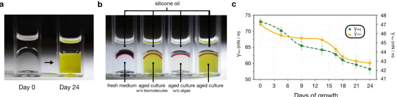
To investigate this phenomenon, we focus on what happens at the interface between cellular medium and oil over time as the cells proliferate. When we take 1 𝑚𝐿 aliquot of cellular medium at two different incubation period (day 0 and day 24) and top it with 0.5 𝑚𝐿 of oil in a cuvette, the medium – oil interface shows dramatic difference, as shown in Figure 2 (a). This change in interfacial curvature from curved to flat indicates that interfacial tension between medium and oil is not constant, rather, it evolves over time as the cells proliferate.
Many studies have shown that algae, photosynthesizing bacteria, and higher plants living in aquatic environments excrete biomolecules that inherently change the chemical composition of the cellular medium [41-48]. A simple experiment shown in Figure 2 (b) reveals that the change in interfacial tension is mainly due to this excretion of biomolecules, rather than algae themselves. In the figure, algae cultures are topped with silicone oil (10 𝑐𝑠𝑡) to show interfacial curvature, and from left to right, the bottom sample represents 1) algae culture taken at day 24 containing both algae and secreted biomolecules, 2) algae culture taken at day 24 after filtering out algae, containing secreted biomolecules only, 3) filtered algae immediately re-dispersed into fresh medium containing no biomolecules, and 4) fresh medium. Notice samples containing secreted biomolecules (sample 1 and 2) show a noticeably different curvature than samples that contain no biomolecules (sample 3 and 4), indicating that it is mainly the excreted biomolecules that changed the culture’s interfacial tension. The degree of change is quite noticeable; interfacial tension of algae culture in air (𝛾!") and in 10 𝑐𝑠𝑡 silicone oil (𝛾#!) dropped from 73 𝑚𝑁/𝑚 to 58.2 𝑚𝑁/𝑚 and from 47 𝑚𝑁/𝑚 to 42.8 𝑚𝑁/𝑚 respectively, over 24 days of incubation when measured via pendant drop method, as shown in Figure 2 (c).
(a) A simple demonstration showing how the curvature of medium – oil interface dramatically differs from one another, when 1 mL aliquot of medium from culture bath was taken at day 0 and 24 and topped with 0.5 mL silicon oil (10 cst), the same oil used to make LIS. (b) A simple demonstration revealing it is mainly the excreted biomolecules, not algae themselves, that change the interfacial tension of the medium during growth. From left to right, 1) algae culture taken at day 24 containing both algae and secreted biomolecules, 2) algae culture taken at day 24 after filtering out algae, containing secreted biomolecules only, 3) filtered algae immediately re-dispersed into fresh medium with no biomolecules, and 4) fresh medium, each topped with silicone oil (10 cst) to show interfacial curvature. See Materials and Methods for details of incubation. (c) Measurements of interfacial tension of model micro-organism over 24 days of incubation period using pendant drop method. {w}, {o}, and {a} represents water (algae culture), silicone oil (10 cst), and ambient air.
b c 0 3 6 9 12 15 18 Days of growth ! "# (mN / m) ! $ "% (mN / m) aged culture aged culture w/o algae aged culture w/o biomolecules fresh medium silicone oil 21 24 75 70 65 60 50 48 47 46 45 44 43 42 41 !$"% !"# a Day 0 Day 24
Wetting criterion from Gibbs free energy argument
To understand how the diminution of the culture bath’s interfacial tension we observed earlier selects thermodynamic wetting state of the LIS, we express interfacial energy per unit area (𝐸) for all possible wetting states. For a given LIS, we define two geometrical factors, namely, 1) 𝑟 (surface roughness) as the ratio of total surface area to the area of the solid projected from top and 2) 𝜙 (solid top fraction) as the ratio of solid top area also to the area of the solid projected from top. Then, 𝐸 for each state becomes 𝐸 %&'()*+,- = 𝛾#!+ 𝑟𝛾#.,
𝐸 ,/,0%&'()*+,- = (1 − 𝜙)𝛾#!+ 𝜙𝛾!.+ (𝑟 − 𝜙)𝛾#., and 𝐸 +1&)2(*= 𝑟𝛾!., following Smith’s
approach [49]. The stable state corresponds to the one that has the lowest interfacial energy, and transition will happen when one state becomes favorable over the other, for example, the
protective oil layer will stay fully spreading on textured solid only when 𝐸 %&'()*+,- < 𝐸 ,/,0%&'()*+,- , 𝐸 +1&)2(*. Introducing spreading factor 𝑆#.(!) defined as 𝛾!.− 𝛾#.− 𝛾#!, where subscript {w}, {s}, and {o} denotes water (medium), solid, and oil respectively, we can write the conditions for each based on two dimensionless parameters ( 5!"($)6
!$ and 70' 809) as : 5!"($) 6!$ > 0 – spreading 70' 809< 5!"($) 6!$ < 0 – non-spreading 5!"($) 6!$ < 70' 809 – impaled
Therefore, fouling is totally prevented only when 5!"($)6
!$ remains positive. As soon as it
cells to foul. When 5!"($)6
!$ drops below
70'
809, the situation worsens as the whole texture becomes
impaled by the medium providing much more area for cells to foul. This postulation is graphically represented in Figure 3 (a).
To verify this, we first plot evolution of 5!"($)6
!$ as a function of incubation time, for our
model micro-organism grown in seawater like solution (see Materials and Methods for details), as a consequence of change in interfacial tension. As shown in Figure 3 (b), the value starts off from a positive value, then gradually drops below 0, and saturates at a negative value of - 0.149 (call it 5!"($)6
!$ 8:;<). This trend implies that 1) our LIS, for whatever hard substrate geometry, is
expected to experience wetting transition from spreading to non-spreading on day 6, and 2) the LIS will experience further wetting transition from non-spreading to impaled if its 80970' is above
5!"($)
6!$ 8:;<, while LIS with
70'
809 below 5!"($)
6!$ 8:;<will manage to maintain its wetting state as
non-spreading.
Next, we perform microscope observation of algae residue on LIS, after shedding a puddle of algae that have been grown on top of LIS (see Materials and Methods for details). If any algae residue is found on solid part of LIS, we assume it is due to the delamination of oil at that particular region. In this test, we use two model substrates, one with post spacing of 50 𝜇𝑚 and the other with 5 𝜇𝑚, with an expectation to observe impaled state for the 50 𝜇𝑚 case, but not for the 5 𝜇𝑚 case at day 26, given that 70'
809 8= >: .?"@;<A < 5!"($)
6!$ 8:;<<
70'
809 8=B >: .?"@;<A.
Figure 3 (c) reports the locations of algae residue that match very well to our postulation made earlier. To briefly illustrate, on day 3, both LIS with post spacing of 50 𝜇𝑚 and
spreading state, since 5!"($)6
!$ > 0. On day 12, we find algae cells adhered on top of micro-posts in
both substrates since 5!"($)6
!$ has fallen below 0, making the oil non-spreading. On day 24, algae
residues are found in between solid textures for 50 𝜇𝑚 spacing case, as 5!"($)
6!$ value has dropped
below its 80970', letting algae medium get impaled into the textures. On the other hand, no algae is found in between textures in 5 𝜇𝑚 spacing case, since its wetting state remains non-spreading as
5!"($)
6!$ value has not fallen below
70'
809. One interesting observation in the impaled image of 50 𝜇𝑚
spacing is that we see circular ring patterns around each post and no algae on post tops. We assume that this is because the oil was locked beneath the puddle of algae forming a dome around each post, as the medium – oil interface was being pressed down towards bottom of solid substrate during wetting transition from non-spreading to impaled.
spreading non-spreading impaled
a
a
Incubation time (days)
0 3 6 9 12 15 18 21 0.05 0.00 - 0.05 - 0.10 - 0.15 24
b
c
Marine micro-organism Excreted biomolecules !"#"$ $"#"%" &"'()*+ ,"*- ."/ &"'()*+ ,"*- 0"/ 0 &"'()*+ ,"*- 0 !"#"$ $"#"%" &"'()*+ ,"*-day 3 day 12 day 24
spreading non-spreading impaled
spreading non-spreading non-spreading
123 &"'()*+ ," *-0" !"#"$$"#"% " !"#"$ $"#"%" 123 &"'()*+ ," *-." 123 &"'()*+ ,"
*-(a) Schematic illustration of three possible wetting states of LIS immersed in aquatic cellular environment. Dimensionless spreading factor !!"($)
"!$ dictates the wetting state, and fouling is expected to
be prevented only when !!"($)
"!$ > 0. (b) Evolution of
!!"($)
"!$ during growth period of model micro-organism
Nannochloropsis oculata (see Mat. and Methods for details), as a consequence of medium’s diminution of surface tension. At day 9, the value falls under 0, indicating the LIS will experience wetting transition from spreading to non-spreading, regardless of texture geometry. (c) Series of SEM images of algae residue found on hard substrates on day 3, 12, and 24. Hard substrate geometries are selected with the intention of one being !!"($)"
!$ ,#$% <
&'(
('∅ and the other being !!"($)
"!$ ,#$% >
&'( ('∅ .
In situ confirmation of final wetting state via confocal imaging
Now, to eliminate any concern due to physical intervention, such as shedding, we visualize the medium – oil interface using Confocal Laser Scanning Microscope and capture wetting state of LIS in situ. As shown in Figure 4 (a), a transparent LIS (Glass – SU8 LIS) was fabricated (see Material and Methods for details) and puddle of algae was grown on top, under the same incubation environment as before. Figure 4 (b) displays the final shape of the medium – oil interface at day 24 in red. As expected, in 50 𝜇𝑚 spacing case, the interface is clearly bent inwards to the bottom of solid substrate, showing the wetting state is impaled. The interface in 5 𝜇𝑚 spacing case remains flat, indicating the wetting state is non-spreading.
(a) Schematic illustration of Confocal Laser Scanning Microscopy setup for visualizing medium – oil interface in situ. (b) In situ visualization of LIS wetting state at day 16. Here, XY, XZ and YZ slice of confocal Z stack images are shown in the case of 50 µm spacing (left) and 5 µm spacing (right). A clear curvature down towards texture bottom is shown in red for 50 µm spacing case (impaled), whereas the curvature is flat in the case of 5 µm (not-impaled).
b
a
Confocal lens Cover glass SU8 impaled non-spreading Algal puddleRoll-off angle analysis
Algal puddles grown on top of LIS possess different mobilities corresponding to their affiliated wetting states at each moment. In fact, when a LIS is in spreading state, the algal puddle on top should be extremely mobile, owing to the presence of oil lubricant layer underneath the liquid making it extremely slippery. Once wetting transition happens from spreading to non-spreading, algal liquid’s contact with the solid (texture tops) will pin itself, making it less slippery. If it becomes impaled, the degree of pinning will be more pronounced.
To rationalize the degree of slipperiness, we introduce roll-off angle 𝛼∗, defined as the
inclined angle of the LIS at which an algal droplet placed on top starts to move. Here, force driving the motion is gravity, while opposing force is the pinning force. Figure 5 (a) reports 𝛼∗ of
algal droplets (5 𝜇𝐿) at day 3, 12, and 24 on LIS with varying post spacings while micro-post dimensions (10 𝜇𝑚 × 10 𝜇𝑚 × 10 𝜇𝑚 ) are kept the same. Depending on the relative magnitude of algal droplet’s 5!"($)6
!$ and substrate’s
70'
809, we color the expected wetting state as blue for
spreading, yellow for non-spreading, and red for impaled. As shown, 𝛼∗on day 3 is near 0 across
all spacings since there is no pinning force. On both day 12 and 24, 𝛼∗ shows a trend of
decreasing initially due to reduced contact with solid tops per unit area as the post spacings increase. Then, it suddenly jumps as the wetting transition happen from non-spreading to impaled state. Next, it starts to increase as the degree of contact algal droplets make with substrate bottom increases as the post spacings become larger.
To confirm presence of line forces specific to each wetting state in a quantitative manner, we do force balance on algal droplets based on previously measured values of 𝛼∗. Driving force,
namely gravity, scales as 𝜌!𝑉𝑔 sin 𝛼∗. Here, 𝜌
!, 𝑉, and 𝑅 are droplet parameters indicating
𝐿𝛾#!D𝑐𝑜𝑠𝜃8D@,!.(#)− 𝑐𝑜𝑠𝜃"FG,!.(#)G, where 𝐿 is the contact perimeter with the solid surface. This 𝐿 depends on the wetting state: 1) 𝐿 = 0 for spreading, 2) 𝐿 = 𝑅𝜙7/I for non-spreading,
and 3) 𝐿 = 𝑅(1 − 𝜙7/I) for impaled. Each algal droplet will start to move once the two forces
are balanced at the inclined angle 𝛼∗. Equating the forces, we obtain:
𝜌!𝑉𝑔 sin 𝛼∗~ 𝐿𝛾
#!D𝑐𝑜𝑠𝜃8D@,!.(#)− 𝑐𝑜𝑠𝜃"FG,!.(#)G
We divide above equation by 𝑅𝛾!# and obtain its dimensionless form as:
Bo f(θ) sin 𝛼∗~ M𝐿
𝑅N D𝑐𝑜𝑠𝜃8D@,!.(#)− 𝑐𝑜𝑠𝜃"FG,!.(#)G
Here, Bo = 𝜌!𝑔𝑉I/J/𝛾
!# is the Bond number, characterizing relative effect of
gravitational force and surface tension force, and f(θ) = 𝑉7/J/𝑅 = OK
J (2 + cos𝜃)(1 − 𝑐𝑜𝑠𝜃)I/
𝑠𝑖𝑛J𝜃T7/Jassuming droplet is a spherical cap making apparent angle of θ [50]. Figure 5 (b)
reports the plot of two dimensionless forces with good linearity (𝑅I ≈ 0.87), confirming
(a) Roll-off angle measurements of algae droplets (5 𝜇𝐿) on LIS with varying post spacings. (b) Plot of dimensionless body force versus dimensionless pinning force showing good agreement with scaling law. Presence of line forces specific to each wetting state is well confirmed.
LIS design map
Finally, from a design perspective, we revisit the wetting criterion previously obtained. The elegant aspect of our wetting criterion is that we have decoupled the growth nature of aquatic cellular environment ( 5!"($)6
!$ ) from the geometric design parameters of one’s LIS (
70' 809 ).
As we saw earlier, though 5!"($)6
!$ falling below 0 can be inevitable, it falling below
70'
809 can be
prevented ahead by placing one’s hard substrate’s 80970' value below the lowest value of 5!"($)6
!$ . In
other words, though one may have no choice than to let the cellular medium tough textures tops (non-spreading), one is now endowed with the ability to prevent catastrophic failure (impaled) by carefully designing hard substrate geometry.
One trick is to make texture top sharp and pointy, so that even when the medium touches texture tops, the contact stays minimal. If this type of surface displays extremely low 80970', it is even more attractive since it becomes hard to get impaled. A surface that has these two superb characteristics is indeed the low 𝜙 surface. Lots of LIS reported in literature showing great anti-biofouling efficacy are in fact low 𝜙 LIS, including ones with wrinkles or micro-spikes [25, 26, 28, 33-39]. Such surfaces can be easily fabricated by etching micro-post tops via Deep Reactive-Ion Etching (DRIE) to create nanograss. As shown in Figure 5 (a), when tested under same condition, the nano-grassed micro-posts showed significant improvement in anti-biofouling capability compared to the original micro-posts. Here, FITC imaging was used to show the fouled micro-organism and SEM was used to better show the nanograss formed on top of solid posts.
From the knowledge constructed so far, we can construct a regime map that lays out how to design a LIS that can resist medium’s texture impalement. Figure 5 (b) reports such map,
where isolines of 80970' are denoted with series of green lines, and (𝑟, 𝜙) of various textures are plotted with black dots. Red line represents *&'(()
+&( ,,-.value of our model micro-organism, Nannochloropsis oculata, specific to incubation condition previously described. Region above the red line corresponds to zone of no impalement, meaning any texture selected in the zone can resist medium’s texture impalement. Textures in this zone however are subject to letting cells adhere on texture tops at its non-spreading state, but as shown in Figure 5 (a), this can be
minimized by making the texture tops low 𝜙. This low 𝜙 region is denoted in yellow, where two
low 𝜙 surfaces are presented, with one being micron-sized low 𝜙 fabricated using laser ablation technique, and the other being nano-sized low 𝜙 made by DRIE. With the regime map, one can prevent catastrophic loss of oil layer (texture impalement) for any aquatic micro-organism of interest, by measuring *&'(()
+&( ,,-.value, drawing its line on the regime map, and selecting textures
(a) When micro-post tops are textured with nanograss, medium’s contact with texture tops can be
minimized, effectively reducing biofouling. (b) LIS regime map showing zone of no-impalement. Isolines of &'(
('/ are denoted by green lines, (r, ϕ) of various textures are plotted with black dots, and region of low
ϕ LIS is denoted by yellow. Red line denotes !!"($)
"!$ ,#$% value of our model micro-organism, and textures
selected in the region above the red line are safe from cellular medium’s texture impalement.
Chapter 3: Materials and Methods
LIS fabrication
Standard photolithography process was deployed to create arrays of cubic micro-posts on silicon wafer. Dimension of cubic posts were 10 𝜇𝑚 × 10 𝜇𝑚 × 10 𝜇𝑚, where post spacing was varied from 5 𝜇𝑚 to 100 𝜇𝑚. Each substrate’s geometric factors are listed in table 1.
Post spacing ( 𝜇𝑚 ) 5 10 25 50 65 75 85 100 𝑟 2.778 2 1.327 1.111 1.071 1.055 1.044 1.033 𝜙 0.444 0.25 0.082 0.028 0.0178 0.014 0.011 0.008 1 − r 𝑟 − 𝜙 - 0.762 - 0.571 - 0.262 - 0.103 - 0.068 - 0.053 - 0.043 - 0.032
Table 1. Geometric factors of hard substrate of LIS used in this study.
After piranha-cleaning each substrate, samples were coated with Octadecyl
trichlorosilane (OTS) through solution deposition to render the surface hydrophobic. Coated samples were dipped into silicone oil (10 𝑐𝑠𝑡) and withdrawn at speed low enough that the capillary number stays below 100= to ensure no excess fluid remains on post tops. Both OTS and
silicone oil (10 𝑐𝑠𝑡) were purchased from Sigma-Aldrich (USA). Same process was applied to build arrays of SU8 micro-post on top of glass to make Glass – SU8 LIS. Hard substrate with low solid top fractions were made by applying laser ablation technique to bare silicon wafers.
Aquatic cell culture environment
Green algae Nannochloropsis oculata (LB 2164) in artificial seawater medium was purchased from UTEX and used as a model organism. All samples of algae were incubated in a humidified chamber at 25 ℃ with light cycle of 12 ℎ / 12 ℎ day / night of 100 𝜇𝑚𝑜𝑙 𝑚0I𝑠07.
Sample was carefully aspirated using pipette once a day to prevent cell sedimentation.
Goniometry and tensiometry
Contact angles of algae droplets on OTS-treated silicon surface in the presence of air (𝜃!.(")) as well as the interfacial tension of algae droplets in air (𝛾!") and in oil (𝛾!#) was
measured using Ramé-Hart Model 500 Advanced Goniometer / Tensiometer to calculate 5!"($)6
$!
value at different instants of algae incubation. Here, Young’s equation was used to express 5!"($)6
$!
as 06$&@#.L$"(&)MIB.7
6$! − 1, where 𝜃#.(") = 0 and 𝛾#" = 20.1 𝑚𝑁/𝑚 for subscript {o} being
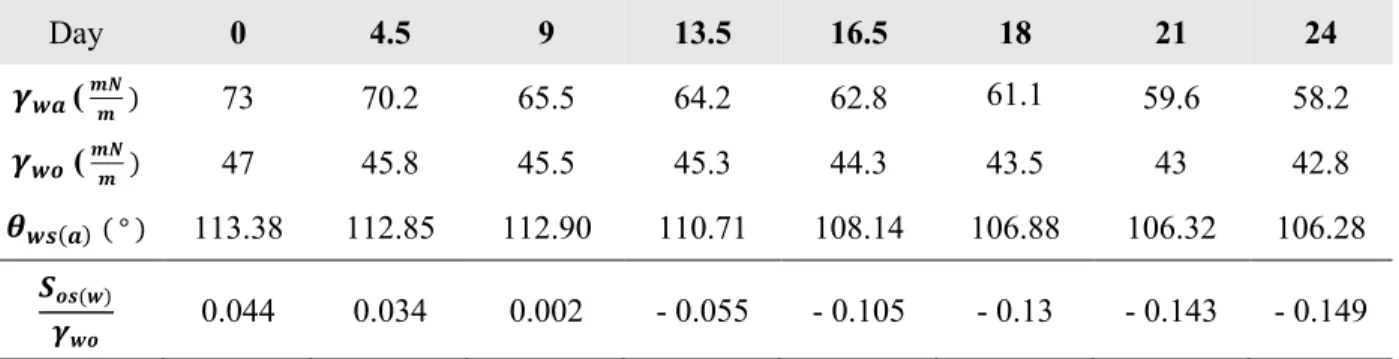
silicone oil (10 cst) purchased from Sigma-Aldrich (USA), {s} being OTS-coated silicon, and {a} being air. Table 2. summarizes the measured values.
Day 0 4.5 9 13.5 16.5 18 21 24 𝜸𝒘𝒂 ( 𝒎𝑵𝒎 ) 73 70.2 65.5 64.2 62.8 61.1 59.6 58.2 𝜸𝒘𝒐 ( 𝒎𝑵𝒎 ) 47 45.8 45.5 45.3 44.3 43.5 43 42.8 𝜽𝒘𝒔(𝒂)( ° ) 113.38 112.85 112.90 110.71 108.14 106.88 106.32 106.28 𝑺𝒐𝒔(𝒘) 𝜸𝒘𝒐 0.044 0.034 0.002 - 0.055 - 0.105 - 0.13 - 0.143 - 0.149
With the same device, receding and advancing contact angles of algae droplet on OTS-treated silicon surface in the presence of oil, 𝜃8D@,!.(#) and 𝜃"FG,!.(#), and roll-off angles (𝛼∗)
were also measured to scale pinning and body forces. When measuring 𝛼∗, sample stage was
tilted with the lowest speed possible, i.e., rate of 0.5 °/𝑠. When measuring both receding and advancing contact angles, droplet volume addition and subtraction rates were carefully selected such that contact line velocities remain slow enough to keep the capillary number below 100=.
This is to spot contact angles right after contact line comes to rest. All data was constructed after taking an average of 5 measurements per sample.
Cell residue imaging
To capture algae residue on hard substrate of LIS, puddles of algae was placed on top of each LIS with different spacings and incubated in the chamber. At different instants of
incubation, puddles were shed, and the LIS were gently rinsed with aceton to remove oil and leave behind the adhered algae only. The hard substrate was immediately brought under SEM to be imaged. FITC imaging technique was deployed to image live algae as shown in Figure 7. Here, the green color is the light received from chlorophyll of algal cells.
Confocal Laser Scanning Microscopy imaging
Oil – water curvature of an algae droplet on LIS with high optical transparency was obtained using Olympus FV1200 Laser Scanning Confocal Microscope (LSCM). Z stack of 42 slices of LSCM images with 1 𝜇𝑚 step was obtained using 30 𝑋 silicone oil objective lens with NA 1.05. Blue laser at 473 𝑛𝑚 was used to excite SU8 post structure and the algae to obtain green signal out from bandwidth filter (490 − 540 𝑛𝑚). Having confirmed the presence of algae in between post textures in the case of 50 𝜇𝑚 spacing, another algae droplet but this time with 0.05 𝑚𝑔/𝑚𝐿 of Rhodamine B (Sigma-Aldrich USA) was placed on the LIS to help image the oil – water curvature in red, using yellow laser at 559 𝑛𝑚 with bandwidth filter of 575 − 675 𝑛𝑚. Same principle was applied to imaging algae and the curvature in the case of LIS with 5 𝜇𝑚 spacing.
Chapter 4: Conclusion
In this study, we proposed and demonstrated cell-growth-induced failure of LIS in aquatic cellular environment, where the secretion of biomolecules by aquatic cells and
subsequent change in interfacial tension of the cellular media induces wetting transitions of LIS such that the protective oil layer is completely lost, resulting in dramatic deterioration of anti-biofouling efficacy of LIS. We modeled and characterized the wetting transitions using two dimensionless factors, one being dimensionless spreading factor of the growth environment ( 5!"($)6
!$ ) and second being the geometry factor of hard substrate (
70'
809 ). Systematic validation of
such modeling was done through series of SEM images of algae residue on hard substrate taken at different instants of incubation. Water – oil interface is visualized using Confocal Laser Scanning Microscopy to capture the cell-growth-induced failure of LIS in situ. Roll-off angle measurement was performed and analyzed to confirm the type and degree of line forces specific to each wetting state. Based on series of validation, a rational design guideline for LIS with robust anti-biofouling capability in aquatic cellular environment is proposed. This new finding may not only find immediate impact in developing robust anti-biofouling LIS for wide range of applications ranging from biomedical devices to underwater structures, but also help elucidate fundamental interaction mechanism between living organisms and submerged surfaces.
Bibliography
1. Bixler, G.D. and B. Bhushan, Biofouling: lessons from nature. Philosophical Transactions of the Royal Society A: Mathematical, Physical and Engineering Sciences, 2012. 370(1967): p. 2381-2417.
2. Wisniewski, N. and M. Reichert, Methods for reducing biosensor membrane biofouling. Colloids and Surfaces B: Biointerfaces, 2000. 18(3-4): p. 197-219.
3. Vo-Dinh, T., Nanotechnology in biology and medicine: methods, devices, and applications. 2007: CRC Press.
4. Shirtliff, M., J.G. Leid, and M. Shirtliff, The role of biofilms in device-related infections. Vol. 2. 2009: Springer.
5. Schulz, M.J., V.N. Shanov, and Y. Yun, Nanomedicine design of particles, sensors, motors,
implants, robots, and devices. 2009: artech house.
6. Railkin, A.I., Marine biofouling: colonization processes and defenses. 2003: CRC press. 7. Copisarow, M., Marine fouling and its prevention. Science, 1945. 101(2625): p. 406-407.
8. Schultz, M., et al., Economic impact of biofouling on a naval surface ship. Biofouling, 2011. 27(1): p. 87-98.
9. Rajagopal, S., et al., Some observations on biofouling in the cooling water conduits of a coastal
power plant. Biofouling, 1991. 3(4): p. 311-324.
10. Rahmani, K., R. Jadidian, and S. Haghtalab, Evaluation of inhibitors and biocides on the
corrosion, scaling and biofouling control of carbon steel and copper–nickel alloys in a power
plant cooling water system. Desalination, 2016. 393: p. 174-185.
11. Yeon, K.-M., et al., Quorum sensing: a new biofouling control paradigm in a membrane
bioreactor for advanced wastewater treatment. Environmental science & technology, 2008. 43(2):
p. 380-385.
12. Ivnitsky, H., et al., Characterization of membrane biofouling in nanofiltration processes of
wastewater treatment. Desalination, 2005. 185(1-3): p. 255-268.
13. Brooks, J.D. and S.H. Flint, Biofilms in the food industry: problems and potential solutions. International journal of food science & technology, 2008. 43(12): p. 2163-2176.
14. Chmielewski, R. and J. Frank, Biofilm formation and control in food processing facilities. Comprehensive reviews in food science and food safety, 2003. 2(1): p. 22-32.
15. Kumar, C.G. and S. Anand, Significance of microbial biofilms in food industry: a review. International journal of food microbiology, 1998. 42(1-2): p. 9-27.
16. Sathe, P., et al., Bioinspired nanocoatings for biofouling prevention by photocatalytic redox
reactions. Scientific reports, 2017. 7(1): p. 3624.
17. Banerjee, I., R.C. Pangule, and R.S. Kane, Antifouling coatings: recent developments in the
design of surfaces that prevent fouling by proteins, bacteria, and marine organisms. Advanced
materials, 2011. 23(6): p. 690-718.
18. Genzer, J. and K. Efimenko, Recent developments in superhydrophobic surfaces and their
relevance to marine fouling: a review. Biofouling, 2006. 22(5): p. 339-360.
19. Meyer, B., Approaches to prevention, removal and killing of biofilms. International biodeterioration & biodegradation, 2003. 51(4): p. 249-253.
20. Zhao, L., et al., Antibacterial coatings on titanium implants. Journal of Biomedical Materials Research Part B: Applied Biomaterials, 2009. 91(1): p. 470-480.
21. Costerton, J.W., P.S. Stewart, and E.P. Greenberg, Bacterial biofilms: a common cause of
persistent infections. science, 1999. 284(5418): p. 1318-1322.
22. Hall-Stoodley, L., J.W. Costerton, and P. Stoodley, Bacterial biofilms: from the natural
environment to infectious diseases. Nature reviews microbiology, 2004. 2(2): p. 95.
23. Lafuma, A. and D. Quéré, Slippery pre-suffused surfaces. EPL (Europhysics Letters), 2011. 96(5): p. 56001.
24. Epstein, A.K., et al., Liquid-infused structured surfaces with exceptional anti-biofouling
25. Tesler, A.B., et al., Extremely durable biofouling-resistant metallic surfaces based on
electrodeposited nanoporous tungstite films on steel. Nature communications, 2015. 6: p. 8649.
26. Ware, C.S., et al., Marine antifouling behavior of lubricant-infused nanowrinkled polymeric
surfaces. ACS applied materials & interfaces, 2018. 10(4): p. 4173-4182.
27. MacCallum, N., et al., Liquid-infused silicone as a biofouling-free medical material. ACS Biomaterials Science & Engineering, 2014. 1(1): p. 43-51.
28. Li, J., et al., Hydrophobic liquid-infused porous polymer surfaces for antibacterial applications. ACS applied materials & interfaces, 2013. 5(14): p. 6704-6711.
29. Badv, M., et al., Lubricant-infused surfaces with built-in functional biomolecules exhibit
simultaneous repellency and tunable cell adhesion. ACS nano, 2018. 12(11): p. 10890-10902.
30. Kratochvil, M.J., et al., Slippery liquid-infused porous surfaces that prevent bacterial surface
fouling and inhibit virulence phenotypes in surrounding planktonic cells. ACS infectious diseases,
2016. 2(7): p. 509-517.
31. Chen, J., et al., An immobilized liquid interface prevents device associated bacterial infection in
vivo. Biomaterials, 2017. 113: p. 80-92.
32. Yuan, S., et al., Liquid-infused poly (styrene-b-isobutylene-b-styrene) microfiber coating prevents
bacterial attachment and thrombosis. ACS applied materials & interfaces, 2016. 8(33): p.
21214-21220.
33. Yuan, S., et al., Facile fabrication of lubricant-infused wrinkling surface for preventing thrombus
formation and infection. ACS applied materials & interfaces, 2015. 7(34): p. 19466-19473.
34. Wang, P., D. Zhang, and Z. Lu, Slippery liquid-infused porous surface bio-inspired by pitcher
plant for marine anti-biofouling application. Colloids and Surfaces B: Biointerfaces, 2015. 136: p.
240-247.
35. Wang, P., et al., Fabrication of slippery lubricant-infused porous surface for inhibition of
microbially influenced corrosion. ACS applied materials & interfaces, 2016. 8(2): p. 1120-1127.
36. Wang, P., Z. Lu, and D. Zhang, Slippery liquid-infused porous surfaces fabricated on aluminum
as a barrier to corrosion induced by sulfate reducing bacteria. Corrosion Science, 2015. 93: p.
159-166.
37. Yin, J., et al., Self-cleaning and antibiofouling enamel surface by slippery liquid-infused
technique. Scientific reports, 2016. 6: p. 25924.
38. Wei, C., et al., Silicone oil-infused slippery surfaces based on Sol–Gel process-induced
nanocomposite coatings: A facile approach to highly stable bioinspired surface for biofouling
resistance. ACS applied materials & interfaces, 2016. 8(50): p. 34810-34819.
39. Doll, K., et al., Development of laser-structured liquid-infused titanium with strong
biofilm-repellent properties. ACS applied materials & interfaces, 2017. 9(11): p. 9359-9368.
40. Wang, P., et al., Fabrication of slippery lubricant-infused porous surface with high underwater
transparency for the control of marine biofouling. ACS applied materials & interfaces, 2016. 9(1):
p. 972-982.
41. Volk, R.-B. and F.H. Furkert, Antialgal, antibacterial and antifungal activity of two metabolites
produced and excreted by cyanobacteria during growth. Microbiological Research, 2006. 161(2):
p. 180-186.
42. HANSSON, L.A., et al., Cyanobacterial chemical warfare affects zooplankton community
composition. Freshwater Biology, 2007. 52(7): p. 1290-1301.
43. Riahi, H., A. Eskash, and Z. Shariatmadari. Effect of bacterial and cyanobacterial culture on
growth, quality and yield of Agaricus bisporus. in Proceedings of the 7th International Conference on Mushroom Biology and Mushroom Products (ICMBMP7) Section: Waste Conversion, Substrates and Casing. 2011.
44. Singh, R., et al., Uncovering potential applications of cyanobacteria and algal metabolites in
biology, agriculture and medicine: current status and future prospects. Frontiers in microbiology,
2017. 8: p. 515.
45. Kind, T., et al., Qualitative analysis of algal secretions with multiple mass spectrometric
46. Hellebust, J.A., EXCRETION OF SOME ORGANIC COMPOUNDS BY MARINE
PHYTOPLANKTON 1. Limnology and Oceanography, 1965. 10(2): p. 192-206.
47. Czeczuga, B., et al., Effect of Aquatic Plants on the Abundance of Aquatic Zoosporic Fungus
Species. Polish Journal of Environmental Studies, 2005. 14(2).
48. Fogg, G.E., Extracellular products of algae in freshwater. Ergebnisse der Limnologie, 1971. 49. Smith, J.D., et al., Droplet mobility on lubricant-impregnated surfaces. Soft Matter, 2013. 9(6): p.
1772-1780.
50. Quéré, D., M.-J. Azzopardi, and L. Delattre, Drops at rest on a tilted plane. Langmuir, 1998. 14(8): p. 2213-2216.
Appendix: Python code
Roll-off angle
import numpy as np # math operations
import pandas as pd # table operations
import matplotlib.pyplot as plt # plotting
from matplotlib.ticker import (MultipleLocator,
FormatStrFormatter,AutoMinorLocator) # tick locator
# Importing
d = pd.read_excel('Roll_off_angle.xlsx', 'test')
# Grouping g = d.groupby('liq') fa = g.get_group('fa') ia = g.get_group('ia') aa = g.get_group('aa')
fa_s = fa.groupby('state')
fa_s1 = fa_s.get_group(1)
fa_s1_v = fa_s1.groupby('vol')
fa_s1_v5 = fa_s1_v.get_group(5.000000e-09)
ia_s = ia.groupby('state')
ia_s2 = ia_s.get_group(2)
ia_s3 = ia_s.get_group(3)
ia_s2_v = ia_s2.groupby('vol')
ia_s2_v5 = ia_s2_v.get_group(5.000000e-09)
ia_s3_v = ia_s3.groupby('vol')
ia_s3_v5 = ia_s3_v.get_group(5.000000e-09)
aa_s = aa.groupby('state')
aa_s2 = aa_s.get_group(2)
aa_s3 = aa_s.get_group(3)
aa_s2_v = aa_s2.groupby('vol')
aa_s2_v5 = aa_s2_v.get_group(5.000000e-09)
aa_s3_v = aa_s3.groupby('vol')
aa_s3_v5 = aa_s3_v.get_group(5.000000e-09)
# Plotting
ticks=np.array([1,2,3,4,5,6,7,8])
plt.scatter(ticks,fa_s1_v5['alpha_avg'],label = 'Day 3 - spreading',zorder=1,marker="o",c="#252C8C",s=70)
plt.scatter(np.array([1,2,3,4,5]),ia_s2_v5['alpha_avg'],label = 'Day 12 - non-spreading', zorder=2, marker="^", c="#FE9A16", s=80)
plt.scatter(np.array([6,7,8]),ia_s3_v5['alpha_avg'],label = 'Day 12 - impaled', zorder=3, marker="^", c="#CB1D26", s=80)
non-plt.scatter(np.array([4,5,6,7,8]),aa_s3_v5['alpha_avg'],label = 'Day 24 - impaled', zorder=5, marker="x", c="#CB1D26", s=80)
plt.xticks(ticks,labels=([5, 10, 25, 50, 65, 75, 85, 100]),fontsize=13)
plt.xlabel('post spacings (um)',fontsize=15)
plt.ylabel('roll off angle (º)',fontsize=15)
plt.legend(loc='center left', bbox_to_anchor=(0.61, 0.32))
plt.rc('ytick',labelsize=13)
Force balance
import numpy as np # math operations
import pandas as pd # table operations
import matplotlib.pyplot as plt # plotting
from itertools import chain # for the ease of merging ranges
# Grouping g = df.groupby('liq') fa = g.get_group('fa') ia = g.get_group('ia') aa = g.get_group('aa')
fa_s = fa.groupby('state')
fa_s1 = fa_s.get_group(1)
fa_s1_v = fa_s1.groupby('vol')
fa_s1_v5 = fa_s1_v.get_group(5.000000e-09)
ia_s = ia.groupby('state')
ia_s2 = ia_s.get_group(2)
ia_s3 = ia_s.get_group(3)
ia_s2_v = ia_s2.groupby('vol')
ia_s2_v5 = ia_s2_v.get_group(5.000000e-09)
ia_s3_v = ia_s3.groupby('vol')
ia_s3_v5 = ia_s3_v.get_group(5.000000e-09)
aa_s = aa.groupby('state')
aa_s2 = aa_s.get_group(2)
aa_s3 = aa_s.get_group(3)
aa_s2_v = aa_s2.groupby('vol')
aa_s2_v5 = aa_s2_v.get_group(5.000000e-09)
aa_s3_v = aa_s3.groupby('vol')
aa_s3_v5 = aa_s3_v.get_group(5.000000e-09)
# Body forces using Bond number
g = 9.81
n_bf_fa_s1_v5 =
fa_s1_v5["rho"]*(fa_s1_v5["vol"]**(2/3))*g/fa_s1_v5["gamma_ow"]*np.sin(fa_s1_ v5["alpha_avg"]*np.pi/180)*1000
n_bf_ia_s2_v5 =
ia_s2_v5["rho"]*(ia_s2_v5["vol"]**(2/3))*g/ia_s2_v5["gamma_ow"]*np.sin(ia_s2_ v5["alpha_avg"]*np.pi/180)*1000
n_bf_ia_s3_v5 =
ia_s3_v5["rho"]*(ia_s3_v5["vol"]**(2/3))*g/ia_s3_v5["gamma_ow"]*np.sin(ia_s3_ v5["alpha_avg"]*np.pi/180)*1000
n_bf_aa_s2_v5 =
aa_s2_v5["rho"]*(aa_s2_v5["vol"]**(2/3))*g/aa_s2_v5["gamma_ow"]*np.sin(aa_s2_ v5["alpha_avg"]*np.pi/180)*1000
n_bf_aa_s3_v5 =
# Pinning forces
n_pf_fa_s1_v5 =
0*fa_s1_v5["R"]/1000*fa_s1_v5["phi^(0.5)"]*(np.cos(20*np.pi/180
)-np.cos(60*np.pi/180)) # dropped by multiplying zero, to meet Smith's paper
n_pf_ia_s2_v5 =
ia_s2_v5["phi^(0.5)"]*(np.cos(ia_s2_v5["theta_rec_ws_o"]*np.pi/180
)-np.cos(ia_s2_v5["theta_adv_ws_o"]*np.pi/180))
n_pf_ia_s3_v5 = (1
-ia_s3_v5["phi^(0.5)"])*(np.cos(ia_s3_v5["theta_rec_ws_o"]*np.pi/180
)-np.cos(ia_s3_v5["theta_adv_ws_o"]*np.pi/180))
n_pf_aa_s2_v5 =
aa_s2_v5["phi^(0.5)"]*(np.cos(aa_s2_v5["theta_rec_ws_o"]*np.pi/180
)-np.cos(aa_s2_v5["theta_adv_ws_o"]*np.pi/180))
n_pf_aa_s3_v5 = (1
-aa_s3_v5["phi^(0.5)"])*(np.cos(aa_s3_v5["theta_rec_ws_o"]*np.pi/180
)-np.cos(aa_s3_v5["theta_adv_ws_o"]*np.pi/180))
# Plotting
plt.scatter(n_pf_fa_s1_v5, n_bf_fa_s1_v5, label = 'Day 3 - afloat',
zorder=1, marker="o", c="#252C8C", s=70)
plt.scatter(n_pf_ia_s2_v5, n_bf_ia_s2_v5, label = 'Day 9 - tangent',
zorder=2, marker="^", c="#FE9A16", s=80)
plt.scatter(n_pf_ia_s3_v5, n_bf_ia_s3_v5, label = 'Day 9 - impaled',
zorder=3, marker="^", c="#CB1D26", s=80)
plt.scatter(n_pf_aa_s2_v5, n_bf_aa_s2_v5, label = 'Day 14 - tangent', zorder=4, marker="x", c="#FE9A16", s=80)
plt.scatter(n_pf_aa_s3_v5, n_bf_aa_s3_v5, label = 'Day 14 - impaled', zorder=5, marker="x", c="#CB1D26", s=80)
plt.xlabel('non dimensional pinning force',fontsize=15)
plt.ylabel('non dimensinal body force',fontsize=15)
plt.legend(loc='center left', bbox_to_anchor=(1.1, 0.8))
plt.xlim(-0.005,0.08) plt.ylim(-0.005,0.26) plt.tick_params(labelsize=14)
# Plotting & Line regression
combined_n_x =
pd.concat([n_pf_fa_s1_v5,n_pf_ia_s2_v5,n_pf_ia_s3_v5,n_pf_aa_s2_v5,n_pf_aa_s3 _v5])
combined_n_y =
pd.concat([n_bf_fa_s1_v5,n_bf_ia_s2_v5,n_bf_ia_s3_v5,n_bf_aa_s2_v5,n_bf_aa_s3 _v5])
nd = {'x': combined_n_x, 'y': combined_n_y}
ND = pd.DataFrame(data = nd)
b3, m3 = polyfit(ND.x, ND.y, 1)
plt.plot(ND.x, b3 + m3 * ND.x,'-.',color='#139450',linewidth=0.8)