Design of Hybrid Optio- Vision Tracking System with Active RFID
DESIGN OF HYBRID OPTIO-VISION TRACKING SYSTEM WITH ACTIVE RFID BY
ERIC HILTON
SUBMITTED TO THE DEPARTMENT OF MECHANICAL ENGINEERING IN PARTIAL FULFILLMENT OF THE REQUIREMENTS FOR THE DEGREE OF
BACHELOR OF SCIENCE IN MECHANICAL ENGINEERING AT THE
MASSACHUSETTS INSTITUTE OF TECHNOLOGY JUNE 2008
©2008 Eric Hilton. All rights reserved.
The author hereby grants to MIT permission to reproduce and to distribute publicly paper and electronic copies of this thesis document in whole or in part
in any medium now known or hereafter created.
MASSACHULSETTS INSTITUTE OF TECHNOLOGY
i
AUG 14 2008
LIBRARIES
Signature of Author:_
Department of Mechanical Engneerin g
/Date
?
29
2Date y 29 £OO#
Certified by:
Warren Seering Professor 0oMechanical Engineering
Co-Director / Leaders for Manufacturing
Thesis Supervisor Accepted by:_
John H. Lienhard V Professor of Mechanical Engineering Chairman, Undergraduate Thesis Committee
•a Imt
&RGfIawC
EH
Design of Hybrid Optio-Vision Tracking System with Active RFID
Design of Hybrid Object Tracking System with Active RFID and Vision
by
Eric Hilton
Submitted to the Department of Mechanical Engineering on May 9, 2008 in partial fulfillment of the requirements for the Degree of Bachelor of Science in
Mechanical Engineering
ABSTRACT
An investigation in current RFID technology with an envision design
of a hybrid setup with Active RFID and camera technology. Current Active
RFID technologies focus on dynamic mesh networks with complex
functionality on the tag side. Accuracy of is at best a few meters. A proposed
design uses a simpler RSSI model suggest a dynamic positioned antenna to
enhance the accuracy of simple star-shape networks. The design focuses on
a double helical antenna positioned on a motorized dual axis controller.
Thesis Supervisor: Warren Seering
Design of Hybrid Optio- Vision Tracking System with Active RFID EH
TABLE OF CONTENTS
1 INVESTIGATION AND DESIGN OF A RFID COMBINATION WITH VISION INTERFACE
4
1.1 PERSONAL VISION TRACKING SYSTEM FOR OBJECT TRACKING AND RECORDING USING RFID...4
1.2 A PPLICATIONS ... ... 4
1.3 CURRENT TECHNOLOGIES PLACED IN EFFECT. ... ... 5
1.4 CCTV/PASSIVE -N ox ... ... 5
1.5 CCTV/ACTIVE - RFTRAQ ... ... 5
1.6 FREIGHT TRACKING/ACTIVE -AEROSCOUT... ... 6
2 ACTIVE VS. PASSIVE RFID BASICS AND FREQUENCIES ... 6
2.1 PASSIVE R FID ... ... 6
2.1.1 Frequencies and Range... 6
2.1.2 C ost ... ... ... ... 7
2.1.3 A ntennas ... ... ... 7
2.2 A CTIVE R FID ... ... 8
2.2.1 Frequencies and Range... 8
2.3 COST VS BENEFITS... ... 9
3 SYSTEM SETUP AND APPARATUS ... 11
3.1 VISION DESIGN ... ... 11
3.1.1 Logitech Quickcam Pro 9000... ... ... 11
3.1.2 Logitech UltraVision SE Cam era... 11
3.2 SOFTWARE INTEL OPENCV AND COMPUTER SOFTWARE... ... 12
3.3 RFID ANTENNA D ESIGN... 13
3.3.1 A ntenna D esigns... .... ... ... 13
3.4 INTEGRATION OF RFID SETUP ... 14
3.4.1 Camera and RF Antenna Position... 14
3.4.2 Field of Motion Characteristics ... 15
4 FINAL DESIGN ... 18
4.1.1 Field Of View per Cam era ... 18
Design of Hybrid Optio-Vision Tracking System with Active RFID
1
Investigation and Design of a RFID combination with
Vision interface
The center of this thesis is an investigative design in a RFID solution. Focus on the design of low cost RFID device for object oriented tracking. Object tracking is feasible
by various technologies including machine vision and radio identification means. Both
paths have been widely used in industrial applications but an immerging field is the combination of both technologies. While this paper focuses on low cost design, there is emphasis on the limitation of each method.
1.1
Personal Vision Tracking System for object tracking and
recording using RFID
The design focus is on budged personal tracking system by using off the shelf
components to the extent possible and easy to assemble materials. With the exclusion of the RFID reader, this is comprehensive to a student budget by using a laptop as the control element of the design.
1.2 Applications
A hybrid Visio-RFID device has various utilities in application. The ideal environment is a close system setting to distinguish the various objects and or personnel.
The close system requires a known number of individuals in the system. This is either by means of a database or the use of a distinct identifier tags. Such environment is inclusive to cruise-lines, conventions, warehouses, theme parks and so on. In these situations, the
entrance of system is monitored to allow the retrieval of the identifier tags from the participants. Considering cruise lines, the benefit of the apparatus is to find lost children, monitor security zones, and allow methodical data logging for origin analysis in case of virus outbreaks such as the Norwalk virus. These systems are feasible with the addition
Design of Hybrid Optio-Vision Tracking System with Active RFID
of multiple apparatuses and a backend database engines to distinguish and recall
participants, by monitoring timestamps and location using complex inventory algorithms.
Another viable and individual solution is as a personal Surf Recorder. The elements in this design allow the possibility of such use. The limitation in participants and physical orientation permits a finer resolve in object tracking.
1.3 Current Technologies placed in effect.
As an immerging field there are several industries that have tailored these technologies into their own branded systems. The main distinction is in RFID technology due to item level costs and requirement for accuracy.
1.4 CCTV/Passive -Nox
Nox is Passive RFID surveillance system using close circuit television (CCTV). They specialized in primarily short to medium range (proximity to 2m) tracking and alerts due to motion of passive RFID tags. Antenna designs and camera setups are unknown but their website implies event driven tag movements for CCTV recording. They offer a line of tags as Pro-Tags UIDTM. They are sticky and peel tags with embedded antenna and chip.' Tags are most likely 868-928 MHz UHF RFID tags with range limited by the antenna definition and sensitivity.
1.5
CCTV/Active - Rftraq
Rftraq is an Active RFID in-house systems integrator with specialty in medium to ultra range (100s of meters) using European Active RFID ranges of 902 MHz, 915 MHz and 868 MHz2. They work with both high gain directional and omni-directional antenna designs but both elements are static position RFID elements. Their featured Active RFID CCTV is also an event driven tag to drive the CCTV recording.3 Tags are probably sensor driven to signal an interrupt indicator for the backend software in the event of motion.
Design of Hybrid Optio- Vision Tracking System with Active RFID
1.6
Freight Tracking/Active - AeroScout
In both previous cases the readers work by tag event-driven schemes. AeroScout differs in its motion sensing method to focus on the strength and time of arrival signal
algorithms in the Wi-Fi frequency range (2.4 GHz).Their capability allows to distinguish objects in both indoor and outdoor environments.4 Signal strength for indoors and Time of flight for outdoors.
One of the leading RTLS chip designers in the industry, Nanotron Technologies GmbH states a resolution in distance accuracy of 1-2m range using signal location base systems.5 This is using an unique chirp signal for advanced time of flight comparison.
Based on this assessment, AeroScout's RTLS accuracy would be near or still beyond the 2m resolution. Their system functionality would be based on relay of a tag's relative coordinates to proximity tags to the backend. Any deviation from a designate relative norm would trigger an alert on the software backend.
2 Active vs. Passive RFID Basics and Frequencies
With several frequencies and technologies in use in industry which would be best suited for low cost and continuous mid-range monitoring by both RFID and video with high resolution accuracy? It would depend on the application and environment. An ideal setting would be monitoring for indoor coverage of 10m diameter as the case for a retail store with high value items. The attention of this work is on a device object or personnel tracking for indoors.2.1
Passive RFID
Passive RFID systems are usually either Chip-less, HF or UHF systems.
2.1.1
Frequencies and Range
Chip-less systems focus on product theft of items tagged in high volume. With the benefit of extremely low cost tags (less than 0.2 cents) they, do not contain the ability of an unique identifier To distinguish between items, various tags at separate frequencies within (10kHHz- 60Mzh) ranges. Aside from increased manufacturing costs and
Design of Hybrid Optio- Vision Tracking System with Active RFID
calibration of tag frequency-induction, the read ranges of chip-less systems do not extend beyond a mere few feet.
HF- systems are within the 125 KHz, and 13.56 MHz spectrums respectively. The 125 KHz spectrum was an earlier RFID standard primarily for use with Identification Cards. These systems were usually unencrypted and will. The 13.56MHz spectrum allows a wider bandwidth in transmission to encrypting data and query response from the
embedded tag chip. While encryption is a benefit of the query response from the card limits the range of HF systems upto im.
UHF systems are usually within EPC frequency standards (860MHz-960MHz) 6 UHF is better suited for long distance tags reads with an expected range of 1.5m to 10m range
depending on the antenna configuration and signal strength. Encryption is possible but limits the read distances. UHF tags are cheaper than 13.56MHz cards to produce and currently within the (5-20 cent) range.
2.1.2 Cost
The driving limitations in read distances are the antenna and the RFID reader. The leading manufacturing high power RFID reader is a Seattle based company Impinj7 producing the Speedway 1W (+30dbm)8 reader. Their reader specialized on high power and fast reads( at up to 10m range. at a free space loss of -50dbm. With the additional features of 4 channel cycling the Speedway is costly reader ($1200-$2000).
Even though Impinj's reader is in reach of the 10m diameter goal the technology does not provide location services. Additional readers could probably triangulate the tag location by induction response but to the detriment of cost and supplementary noise.
2.1.3 Antennas
Antenna Size is the second impairment to an UHF design. To achieve 10m meter range, the specs recall for a +6dbm to 8dbi antenna. Antennas of this gain with a dielectric barrier of air are usually within a "22 cm x 22 cm x 3cm" as in the case of Hyperlinks 900 MHz 8dbi Patch HG908P-NF9. While a bit bulky, an additional problem is the orientation and type of antenna. A circular polarized antenna can read linear polarized tags in any direction parallel to the ground plane of the antenna. Patch Antennas are
Design ofHybrid Optio- Vision Tracking System with Active RFID
linearly polarized planes are strict in the orientation of the tag. To be clearly read the tag has to be in parallel to the antenna's ground plane and in the same polarization
(orientation) to the excitation plane.
The cost effectiveness in passive RFID is the high volume and low cost of the tags. Without the capability to effortlessly and economically do localization, the attention of the design focuses on the merits of active RFID technology.
2.2
Active RFID
In all the previous companies in sectional 1.3- 1.6 the systems are based on static RFID element designs. The motion detection functionality in 1.4 Nox and 1.5 Rftraq are sensor driven inputs on the tag. The sensor signals an interrupt to the microcontroller unit (MCU) or is polled at a regular interval. Potential sensors compatible with the MCU are low current analog or digital components. Unlike passive RFID tags, active RFID tags have their own internal power source which can power small sensor and the MCU. Several choices power sources are lithium coin cell batteries, AA or AAA alkaline batteries and custom thin film lithium cells.
2.2.1 Frequencies and Range
The Active range of RFID is limited by its environment and carrier frequency. The choice in spectrum has an impact on the signal propagation distance. Active tags are power source driven and can compete in many other spectrums but industry standard is IEEE 802.15.4 with 16 channels in the 2.4GHz ISM band, 10 channels in the 915MHz I and one channel in the 868MHz band.'0
The 433 MHz has a longer wavelength than the options. It is established for outdoor applications for its long range (>100 m). The RTLS resolution is limited by the bandwidth and usually in the 5m to 10m range.
The 2.4 GHz spectrum is focused for indoor layouts. Its shorter wavelength permits transmission about corridors as a wave guide and reflects off solid walls. Broadcast
Design of Hybrid Optio- Vision Tracking System with Active RFID
2.3 Cost vs Benefits
The benefit of Active RFID is the potential for Real Time Location System services (RTLS). The investment ($20-$40) in a Active tag is usually for high value items, freight containers, cold-chain monitoring, and personnel tracking.
There is an ongoing progress to reduce the price to compete as a disposable tag like most passive tags.
There are various RTLS methods5 detail in the white paper by Nanotron Inc. Angle of Arrival (AoA)
Time of Arrival (ToA)
Time Difference of Arrival (TDOA) Received Signal Strength (RSS) Time of Flight (ToF)
Symmetrical Double Sided Two-Way Ranging (SDS-TWR)
Nanotron's nanoLoc TRX IC transmit duration is within 1-41s'1 and boast read rates of upto 500 tags per second".
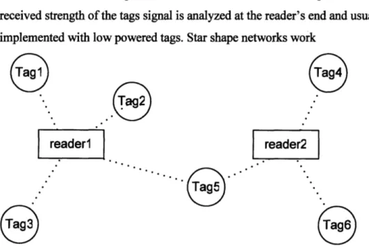
Of these the easiest to implement is the RSS model in a star-shaped net structure. The
received strength of the tags signal is analyzed at the reader's end and usually can be implemented with low powered tags. Star shape networks work
readera reader2
Figure 1 Diagram of Star-Shape Network using two reader nodes.
Design of Hybrid Optio-Vision Tracking System with Active RFID
Figure 1 shows an example of a star-shape network utilized by early active tag designs. Benefits are low power pulses primarily since the neighboring tags do not participate in a listening mode. Star networks are ideal for centralized structures as tags act principally as beacons. Tags can be design in smaller packages with longer lifespan. RSS models are an easier procedure for star nets as the relative distances is reflective to a central node origin. The disadvantage of these networks is obstacles attenuate the signal and skews the
distance correlation to signal. Star nets perform accurately in outdoor environments and at lower frequencies of 433MHz.
reader1
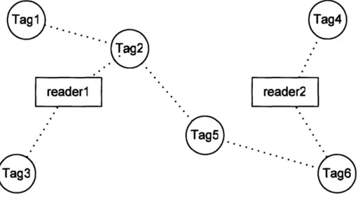
reader2
Figure 2 Example of a Dynamic Mesh Network using two nodes and Communication by Proximity Mesh Networks are more complex models that gear by a decentralized structure (Figure 2). Tags are required to both read and relay communication to neighboring tags to finally cease at a reader node. Tags are usually more demanding in robust power requirements and scales proportionally to their quantity of tags in the system. Benefits are a wide coverage of area and smaller Time of flights (ToF) signals between multiple near tags. A smaller ToF communication permits a stable correlation between distance and the signal.
Design of Hybrid Optio-Vision Tracking System with Active RFID
3 System Setup and Apparatus
3.1
Vision Design
The vision components are standard of the shelf cameras with one as VGA and the other a HD CCD sensor.
3.1.1 Logitech Quickcam Pro 9000
Released in 2002, the QuickCam Pro 4000 can capture 1.3 megapixel still images and 640x480 video with its VGA CCD sensor. Software enabled digital zoom offers the option to pan, tilt and zoom up to five times the normal viewing size. QuickCam Pro 4000 includes a built-in microphone and a convenient snapshot button.
3.1.1.1 Imaging Specs and
Quickcam Pro 4000 specifications of the imaging sensor includes a 640x480 1/6 ccd chip.12 The QuickCam Pro 4000 can capture 1.3 megapixel still images by software
interpolation. The native resolution of the CCD sensor is 640x480 pixels. Its lense are plastic and are set with f-stop setting of 2.4.
3.1.1.2 Connection Speed USB
Connection protocol of the Quickcam Pro 4000 is USB v 1.1. Its speed transfer rates are IMb/s, 2Mb/s, 6Mb/s, and 11Mb/s. For maximum transfer the webcam utilizes 11Mbits/s communication. Near half of transfer speed is used for overhead of packet transfers. Image Packet delivery transfer rates are near the 2Mb/s to 4Mb/s range.
3.1.2
Logitech UltraVision SE Camera
The UltraVision SE boasts a 1.3MP imaging device.
Available in the U.S. and Europe, the QuickCam Ultra Vision webcam has a suggested retail price of $129.99 in the U.S. The camera lens system comprises five extra-large lenses, several of which are made with glass, providing exceptionally sharp and clear video. Most webcams on the market are made up of only plastic lenses, producing images that seem distant and are often distorted.13
Design of Hybrid Optio- Vision Tracking System with Active RFID
3.1.2.1 Imaging Specs
The QuickCam Ultra Vision webcam has a native sensor of 1.3M Pixels. It produces High Definition images and video with USB2.0 on a high end computer. By featuring an f-stop setting of 1.6 the QuickCam Ultra Vision webcam is able to capture more light, producing greater image detail in dimly lighted or back- or side-lighted conditions. Most webcams on the market have an f-stop setting of 2 or greater.
3.1.2.2 Connection Speed USB2.0
USB2.0 permits a maximum transfer rate of 200 Mbits per second at full duplex. The theoretical data image transfer rate would be near 60-90 Mbits per second in single from the camera.
3.2 Software
Intel
OpenCV and Computer Software
Testing was assisted using OpenCV libraries and VB6 on an Intel Pentium 3 1.0GHz computer with 384MB of RAM. Scripts were modeled on example code under the OpenCV tutorials.14
Design of Hybrid Optio- Vision Tracking System with Active RFID
3.3 RFID Antenna Design
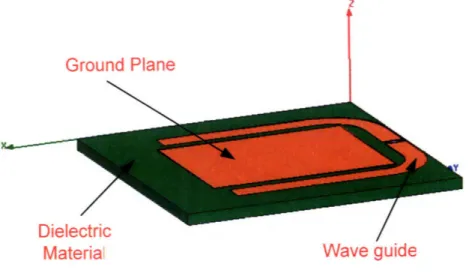
3.3.1 Antenna Designs
Ground
Plane
•MaterlA Ial
Material
Wave guide
Figure 3 Design of RFID Active tag by Tagsense Inc under HFSS v10.1
le'tric
aterial
Figure 4 Elements of a Helix Antenna (Ground Plane, Dielectric material and wave-guide)
EH Design of Hybrid Optio-Vision Tracking System with Active RFID
3.4
Integration
of RFID Setup
3.4.1 Camera and RF Antenna Position
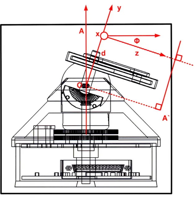
Figure 5 Side-view of Camera Position on Trippy dual-axis controller
Rotational camera element sits at Origin (x,y,z) and translates about point O.
The orthographic projection is the image plane A' and its translation about position
Design of Hybrid Optio-Vision Tracking System with Active RFID
(0.2) z (y,t)= d + y cossin
sin 0
Translation about the Oy-axis is a function of Base rotation which is directly acted on the Camera Ocamera
(0.3)
7, (y,t) = G oi (t) = Ocamera3.4.2 Field of Motion Characteristics
3.4.2.1 Gear Ratio
Figure 6 Angular Rotation of Pivot bar on Trippy Device
Design of Hybrid Optio- Vision Tracking System with Active RFID
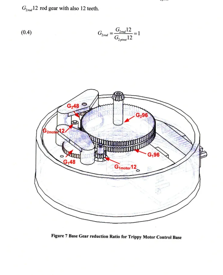
The Top pivot handle incorporates a pivot head with 12 teeth G2piot 12 situated on a
G2rodl 2 rod gear with also 12 teeth.
(0.4) G2rod
G
2rw
2 =1G2 pivot12
Figure 7 Base Gear reduction Ratio for Trippy Motor Control Base
Design ofHybrid Optio- Vision Tracking System with Active RFID EH
G2motor 12 G248
(0.5) Gball = otrod
G248 G296
G 2motor12 G248 1
(0.6) Gbal =2,oto = -reduction
G248 G296 8
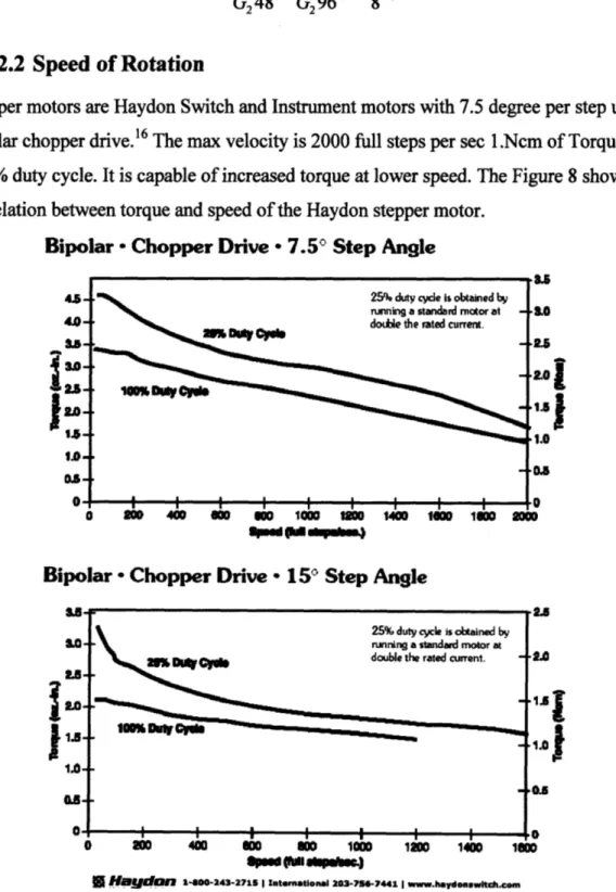
3.4.2.2 Speed of Rotation
Stepper motors are Haydon Switch and Instrument motors with 7.5 degree per step under bipolar chopper drive.16 The max velocity is 2000 full steps per sec 1.Ncm of Torque at 100% duty cycle. It is capable of increased torque at lower speed. The Figure 8 shows the correlation between torque and speed of the Haydon stepper motor.
Bipolar - Chopper Drive * 7.5' Step Angle
45,-
1.
0-&.0
1.0
25% duty cycle is obtained by
running a standard motor at -Ydoue the rated current.
10% crib pse
I I I I I I I I I
0 iol 4C00
eoo
D O 10o0 1O 1400SeO
lowO 20AnBipolar - Chopper Drive - 15C'Step Angle
.0-
1.0-oa
LOA alJ 0 u ma ,mu uu I 1 110 1400 100 ftp eal (i tpW.),B Haygdn 1-00-243-2711 I Intemational 203-756-7441 I www.haydonswich.com
Figure 8 Torque vs Speed of the Haydon 3600-series stepper motors. 25% duty cycle is obtained by running a standard motor at
2double the rated curent.
A-I I I I I I l
Design ofHybrid Optio-Vision Tracking System with Active RFID
With the all-metal case the device has a significant inertial moment which would estimate a speed under generous load up to 200 steps per second. With an 8 gear reduction it the Base device has an approximate angular velocity of
17.50 steps 1800
(0.7) 0(camera (t) =
- .200 1800
8 step sec sec
The Trippy dual-axis controller manages to rotate the design to an expected 180 degree turn in less than a sec. It would have a resolution of
1 7.50 .93750
(0.8) zcamera (step)
-8 step step
This is the angular translation in the Z axis per step at the center of CCD of the camera In respect the angular resolution in the X-axis the center of CCD is by the function is the
same since the ratio of G2rod = 1
4 Final
Design
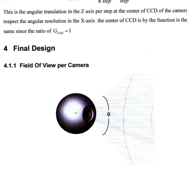
4.1.1
Field Of View per Camera
8i
Figure 9 Angle of Field Angle of Quickcam Pro 4000 focal length = 2mm and field of depth 0=600. The Quickcam UltraVision SE has a focal length of 1.6 and field depth 0=1200
Design of Hybrid Optio-Vision Tracking System with Active RFID
Figure 10 Quickcam Pro 4000 Layout in respect to Ground plane and waveguide.
Cone is the field of vision for the camera in respect to the helix antenna's profile.
Second camera was excluded from the design; the physical structure was not compatible for mounting. The field of depth exceeds the field of depth of the antenna. As shown in Figure 11.
Design of Hybrid Optio- Vision Tracking System with Active RFID
Figure 11 Final Design of Hybrid Vision RFID tracking Antenna.
EH p i
i
~ i ii;+i·r· ~-'3' .j ·,Design ofHybrid Optio- Vision Tracking System with Active RFID
5 Bibliography
1 http://www.simplyvrfid.com/nox/html/Nox.html Nox Video Surveillance
2 http://www.rftraq.com/
RFID Integrator and Surveillance
3http://www.rftrag.com/downloads datasheet pdfs/Active%20RFID%20CCTV%204pp.pdf
4 http://www.aeroscout.com/content/difference Freight Tracking and Cold Chain Tracking
5 http://www.nanotron.com/EN/pdf/WP RTLS.pdf Real Time Location Systems (RTLS)
A White Paper from Nanotron Technologies GmbH vl.02
6http://www.epcglobalus.org/dnn epcus/KnowledgeBase/Browse/tabid/277/DMXModule/706/Command/C
ore Download/Default.aspx?Entryld=297 EPC Global Standards March 8, 2008 v1.03
7 http://www.impini.com/rfid/rfid-reader.aspx Impinj's UHF Reader Passive RFID
8 http://www.impinj.com/uploadedFiles/RFID/RFID Products/Impinj
Speedway-Mini-Spec-Sheet-102007.pdf
Impinj's Speedway UHF Gen 2 Reader Performance Specs 9 http://www.hyperlinktech.com/item.aspx?id=441
900MHz GSM Hyperlink Antenna Specs 10 http://www.ieee802.org/15/pub/TG4.html IEEE 802.15.4 Features
11 http://www.nanotron.com/EN/pdf/Factsheet nanoLOC-NA5TR .pdf NanoTronLoc TX IC Specs Chirp Duration pgl2
12http://www. logitech.com/index.cfl/1 72/1524&cl=us,en QuickCam Pro 4000 Specs
13 http://www.logitech.com/index.cfm/1 72/2599&cl=us,en
Logitech Ultra Vision SE specs
14 http://www.intel.com/technology/computing/opencv/index.htm OpenCV tutorials and download
15 The Confluence of Vision and Control
David J. Kriegman, Gregory D. Hager and A. Stephen Morse Springer-Verlag London Limited 1995
16 http://www.hsi-inc.com/print rotary.php?series=36000
Haydon Switch and Instruments Stepper specs