Design of a Robust, Intuitive Piston Interface for a
Needle Free Injection System
MASACaLEMOF TECHMLOGY
by
AUG
15
201
Michael Thomas Nawrot
LIBRARIES
Submitted to the Department of Mechanical Engineering
in partial fulfillment of the requirements for the degree of
Master of Science in Mechanical Engineering
at the
MASSACHUSETTS INSTITUTE OF TECHNOLOGY
June 2014
@
Massachusetts Institute of Technology 2014. All rights reserved.
Signature redacted
Author...
Department of Mechanical Engineering
May 27th, 2014
Signature redacted
C ertified by ...
...
Ian W. Hunter
.Hatsopoulos Professor of Mechanical Engineering
Thesis Supervisor
Signature redacted
A ccepted by ...
...
David Hardt
Chairman, Department Committee on Graduate Theses
Design of a Robust, Intuitive Piston Interface for a Needle
Free Injection System
by
Michael Thomas Nawrot
Submitted to the Department of Mechanical Engineering on May 27th, 2014, in partial fulfillment of the
requirements for the degree of
Master of Science in Mechanical Engineering
Abstract
The MIT BioInstrumentation Lab's linear Lorentz force actuator based needle free in-jection system has been shown to have numerous benefits over needle-based and other needle-free drug delivery systems in a research environment. While the device has been used extensively on post mortem tissue and live animals, its use on humans has been restricted in large part because of an ineffective drug delivery ampoule interface which compromises sterility. A new ampoule interface has been developed to allow sterility to be maintained, while also improving robustness against manufacturing tolerances and user error. The new ampoule interface has been tested and compared to the previous ampoule interface and shown to have comparable performance during normal use, while also surviving misuse. An intuitive user interface has also been developed which eases the process of mounting and dismounting ampoules.
Thesis Supervisor: Ian W. Hunter
Acknowledgments
First and foremost, I would like to thank my thesis advisor and professor, Dr. Ian Hunter, for the opportunity to work in one of the most inspiring environments I have yet to encounter: the MIT BioInstrumentation Lab. From my earliest work as an undergrad in the lab through to the completion of this thesis, I have had the good fortune of being surrounded by brilliant minds who are constantly engaged in solving difficult problems. Without you, I would have never had such a wonderful opportunity. Beyond the environment you have created for my labmates and me, your wealth of knowledge and enthusiasm have inspired me to broaden my skills and take an active role in my education, for which I will always be grateful.
To Dr. Cathy Hogan, thank you for your mentorship and your friendship. Your guidance was critical to the success of this project, and I could not have done it without you. Your wealth of experience helped keep me organized and focused, even at times when I felt that I had no direction. You taught me to better manage my time and expectations, and did so while providing welcome company through the earliest of mornings, longest of days, and latest of nights. Your knowledge and experience keep this lab functioning.
To Dr. Adam Wahab, thank you for your unending patience. From my early days in the lab as an undergraduate until well after you graduated and moved beyond the lab, you served as a wonderful mentor. I learned so much from you in so little time. Your willingness to take time out of your day to teach me new skills was greatly appreciated. Your contributions to the lab and my personal education would fill volumes. To Dr. Brian Hemond, Dr. Eli Paster, and Ellen Chen, thank you for your friendship and insight. In the most stressful of times, you were there to offer sound advice and comfort through sharing your own experiences with me. To Ashin Modak, thank you for your friendship and your unending willingness to help me through difficult times. Whether it was debugging jet injector controllers, reading through my thesis at odd hours of the night, or just providing a bit of comedy in stressful times, the lab is a much happier place with you around. To the other
members of the lab, thank you for creating the environment which I look forward to coming to every day.
Finally, I must thank my mother and father for teaching me the importance of education from a young age, and always pushing me to push myself. I did not realize how much of an impact you had on my education until I arrived at MIT and gained perspective on the values you had instilled in me from a young age.
Contents
List of Figures 9
List of Tables 17
1 Background 19
1.1 History of Needle-Free Injection . . . . 19
1.2 Parameters Affecting Needle-Free Injection . . . . 20
1.3 A Lorentz Force Actuator Based Jet Injector . . . . 21
1.4 Ampoule Piston and Motor Interface . . . ... . . . 23
1.5 Aims of this Thesis . . . . 24
2 Motor and Drug Delivery Ampoule Piston Interface 27 2.1 Motivations for the Self-Aligning Quick Release (SAQR) Adapter . . 27
2.2 SAQR Functional Requirements . . . . 32
2.3 Early Designs of the SAQR Adapter . . . ... . 36
2.3.1 An Integrated SAQR Adapter . . . . 36
2.3.2 A Flexure-Based SAQR Adapter . . . . 45
2.4 Design of a Floating Ring SAQR Adapter . . . . 51
2.4.1 The Preload Concept . . . . 51
2.4.2 Floating Ring SAQR Architecture . . . . 53
2.4.3 SAQR RevO . . . . 58
2.4.4 SAQR Rev1, Rev2, and Rev3 . . . . 74
2.4.5 SAQR Rev4 . . . . . 99
2.5 Performance of the Floating Ring SAQR . . . 108
2.5.1 Method for Performance Assessment . . . 108
2.5.2 Volume Repeatability . . . . 110
2.5.3 Trajectory Following . . . 116
2.5.4 Tissue Injections . . . 122
2.5.5 Robustness of the Design . . . 126
2.6 Future Improvements to the SAQR Adapter . . . 134
2.6.1 Mounting Improvements . . . 134
2.6.2 Preload Spring Improvements . . . 136
2.6.3 General Improvements . . . 139
2.7 Conclusion . . . 139
3 User Interface for Ampoule Mounting 141 3.1 Early Attempts at Retaining Ring Actuation . . . 141
3.2 The Pin and Slot Style Retaining Ring Actuator . . . 150
3.3 Arm Style Retaining Ring Actuator . . . 158
3.3.1 Arm Style RRA RevO . . . 160
3.3.2 Arm Style RRA Revi . . . 168
3.3.3 Arm Style RRA Rev2 . . . 178
3.3.4 Success of the Retaining Ring Actuator . . . 186
3.4 Conclusion . . . 188
4 Conclusion 191
List of Figures
1-1 A schematic illustration of the jet injection process . . . . 20
1-2 Various aspects of a portable jet injector system . . . . 22
1-3 A comparison between the stock InjexT M [1] ampoule and the modified am poule . . . . 24
2-1 An illustration of radial misalignment between coil and ampoule and its adverse effects . . . . .30 2-2 An illustration of a piston seal affected by misalignment . . . . 31
2-3 An illustration of angular misalignment between coil and ampoule and its adverse effects . . . . 32
2-4 Radial tolerance path from motor coil to ampoule bore . . . . 35
2-5 Exploded view of the integrated SAQR adapter design . . . . 37
2-6 The integrated SAQR adapter in locked and unlocked states . . . . . 38
2-7 Cross section of the integrated SAQR adapter in locked and unlocked states . . . . 39
2-8 Basic finite element analysis of the integrated SAQR cover . . . . 41
2-9 Basic finite element analysis of the integrated SAQR retainer . . . . . 42
2-10 An illustration of tX displacement and rotation of the integrated SAQR retainer . . . . 43
2-11 An illustration of tY and angular misalignment of the integrated SAQR piston . . . . 44
2-12 A schematic of a flexure-based SAQR release mechanism . . . . 46
2-14 A conceptual design of a potential flexure layout for the retainer . . . 48
2-15 Another conceptual design of a potential flexure layout for the retainer 49 2-16 A conceptual design of a potential release flexure design for the SAQR adapter . . . . 50
2-17 A schematic of the preload concept for highly repeatable compliant piston coupling . . . . 52
2-18 A schematic illustrating the forces in piston retraction . . . . 54
2-19 A version of the floating ring SAQR assembly is shown assembled to a simplified version of the current research device . . . . 55
2-20 An illustration of the piston insertion and engagement process . . . . 56
2-21 The degrees of freedom of the floating ring SAQR adapter . . . . 57
2-22 Detail of the retaining ring assembly . . . . 58
2-23 Detail of the adapter body assembly . . . . 59
2-24 Cross section of the floating ring adapter body . . . . 59
2-25 Evolution of the floating ring SAQR design . . . . 60
2-26 View of the RevO floating ring SAQR adapter . . . . 61
2-27 A front view of the RevO capture plate, showing the critical features . 62 2-28 An illustration of how the capture plate engages the forward groove on the piston . . . I . . . . 63
2-29 A view showing the asymmetric retention wedges of the RevO retaining plate . . . . ...66
2-30 A view of the RevO preload springs mounted on the adapter body . . 67
2-31 A demonstration of the wedging and blocking features of the RevO preload spring . . . ... . . . .. . . . 68
2-32 A schematic of the cantilevered preload spring loading with geometry and coordinate definitions . . . . 69
2-33 A basic FEA model of a cantilever-based preload spring . . . . 73
2-34 The three basic loading cases considered for demonstrating a and v . 77 2-35 The Revla preload spring . . . . 82
2-36 Stress distribution from FEA analysis of the Revla, Revib, and Rev2
preload springs . . . . 83
2-37 Diagram of the Rev1b preload spring, showing the most significant changes . . . . 84
2-38 Diagram of the Rev2 preload spring, showing the most significant changes 86 2-39 An illustration of the effects of variable radius fillets on the stress concentrations below the preload wedge . . . . 87
2-40 A comparison of the mounting stress concentrations between Revla, Revib, and Rev2 preload springs . . . . 88
2-41 A comparison of the mounting stress concentrations between different FEA boundary conditions . . . . 89
2-42 The Rev2/Rev3 retaining ring assembly . . . . 91
2-43 The Rev2/Rev3 capture plate . . . . 92
2-44 A comparison of the RevO/Revi and Rev2/Rev3 retaining plates . . . 93
2-45 FEA results for the Rev2 retaining plate flexures . . . . 95
2-46 The Rev2 body assembly . . . . 95
2-47 An exploded view of the Rev2 body assembly . . . . 96
2-48 A side view and cross section of the Rev2 adapter body . . . . 97
2-49 A photograph of the finished Rev2 adapter . . . . 98
2-50 A comparison of the Rev2 and Rev3 SAQR designs . . . . 99
2-51 A cross section showing the ampoule thread boss recessed in the Rev3 adapter body . . . . ...100
2-52 An illustration of the inverted retaining ring configuraton . . . . 101
2-53 The Rev4 retaining ring assembly . . . . 101
2-54 A comparison of the Rev2/Rev2 and Rev4 retaining plates . . . . 103
2-55 A comparison of FEA results from the Rev3 and Rev4 retaining plate flexures . . . . 104
2-56 The Rev4 adapter body assembly . . . . 105
2-58 A comparison between the Rev4 adapter body and the Rev2 adapter body . . . . .106
2-59 The finished Rev4 design mounted to the jet injector . . . 107 2-60 A comparison of ejection volumes with the adapter to ejection volumes
with a threaded piston, 100 pL . . . .- . . . 112 2-61 A comparison of ejection volumes with the adapter to ejection volumes
with a threaded piston, 50 iL . . . 113 2-62 A comparison of ejection volumes with the adapter to ejection volumes
with a threaded piston, 150 pL . . . 114 2-63 The ejected volume of three test ampoules, showing the degradation
of performance over a variety of jet parameters . . . 115 2-64 A comparison of ejection volumes for new, used, and threaded piston,
150 iL . . . 117 2-65 The ejected volume of three new test ampoules, showing the
degrada-tion of performance . . . 118 2-66 A comparison of ejection volumes with the adapter to ejection volumes
with a threaded piston, 200 pL . . . 119 2-67 Temporal position error of ejections with and without the adapter . . 121 2-68 Sectioned tissue from injection set 1 . . . .. . . 125 2-69 Sectioned tissue from injection sets 2 and 3 . . . ..127 2-70 A comparison of the position trajectory following between ejections
and injections . . . 128 2-71 The jet injector with the Rev4 SAQR adapter after a catastrophic failure 129 2-72 Low magnification scanning electron microscope images of used and
unused preload spring mounting points . . . 130 2-73 SEM images of the surface deformation at the preload spring stress
concentrations . . . 131 2-74 SEM images of the preload spring surface topography at the stress
concentration . . . 132 12
2-75 Stress charts from FEA showing the decrease in stress concentration
on the preload spring . . . . 133
2-76 A comparison of alternative mounting methods for the SAQR adapter 135 2-77 An example of a wire-based preload spring . . . . 137
2-78 An example of a stamped preload spring relief . . . . 138
3-1 The manual adapter locking and unlocking process . . . . 143
3-2 The tool for assisting in adapter locking and unlocking . . . . 144
3-3 The tool-assisted adapter locking process . . . . 145
3-4 An illustration showing how the unlock tool design prevents adapter dam age . . . . 146
3-5 The tool-assisted adapter unlocking process . . . . 147
3-6 A comparison between front plate designs . . . . 148
3-7 A demonstration of the locking/unlocking tool being used through the front plate . . . . 149
3-8 An illustration of an intuitive ampoule mounting system . . . . 150
3-9 An illustration of the pin and slot concept . . . . 151
3-10 A diagram of the pin and slot retaining ring actuator rotor . . . . 152
3-11 A cross section of the tool constraint system . . . . 154
3-12 The assembly steps of the RevO pin and slot style retaining ring actuator 155 3-13 The assembly steps of the Rev1 pin and slot style retaining ring actuator 157 3-14 The assembled Revi pin and slot style retaining ring actuator mounted on the Jet Injector . . . . 158
3-15 A schematic demonstration of the arm style retaining ring actuator concept . . . . 159
3-16 An exploded and assembled view of the RevO Arm Style RRA . . . . 160
3-17 A section view of the RevO arm style RRA, showing the rotor actuating the lock and unlock cams . . . . 161 3-18 The RevO locking arm, showing the cam profiles and mounting features 162
3-19 The RevO unlocking arm, showing the cam profiles, mounting features, and end fork . . . 163 3-20 The RevO rotor . . . 164 3-21 A cross section of the RevO rotor, showing the various components and
constraints . . . 165 3-22 A diagram of the RevO arm style SAQR-RRA front plate . . . 166 3-23 A photograph of the RevO rotor, displaying the rough bearing surface 168 3-24 An exploded and assembled view of the Revi Arm Style RRA . . . . 169 3-25 The Rev1 locking arm, showing the cam profiles and mounting features 170 3-26 The RevO unlocking arm, showing the cam profiles, mounting features,
and end fork . . . 171 3-27 A comparison between shallow v-groove and deep v-grooves for cam
pivot constraint . . . 171 3-28 The Revi rotor . . . 173 3-29 A cross section of the Rev1 rotor, showing the various components and
constraints . . . 174 3-30 A photograph of the Revi rotor, displaying the smooth bearing surface 175 3-31 A photograph of the assembled Rev1 retaining ring actuator . . . 176 3-32 A photograph of the Rev1 cam surface finish under 1.75x magnification177 3-33 An exploded and assembled view of the Rev2 Arm Style RRA . . . . 178
3-34 A comparison between the Rev2 locking cam and the Revi locking cam 179 3-35 A comparison between the Rev2 unlocking cam and the Revi unlocking
cam . . . 180 3-36 A photograph of the Rev2 cam surface finish under 1.75x magnification 180 3-37 A comparison between the Revi end fork and the Rev2 end fork, and
their capture plates .. . .. . . 182
3-38 A comparison between the RevO rotor and Rev2 rotor . . . 184 3-39 A diagram showing the return spring being compressed while the RRA
unlocks the adapter . . . 187 14
3-40 A photograph of the Jet Injector with SAQR Rev4 and SAQR-RRA Rev2 mounted . . . . 188
List of Tables
2.1 Functional requirements for a Self-Aligning Quick Release adapter . 33
2.2 Tabulated tolerance values for worst case motor-piston radial misalign-m ent . . . . 35 2.3 Tabulated results of FEA studies on simplified cantilever preload springs 74 2.4 Tabulated dimensions and FEA data for Revla, Revib, and Rev2
preload springs . . . . 83 2.5 Mean and standard deviation of ejected volumes . . . . 120 2.6 Jet parameters used for tissue injections . . . . 124
2.7 Measured injected and ejected mass/volume for injection set 1 . . . . 125 2.8 Measured injected and ejected mass/volume for injection sets 2 and 3 126
3.1 Tooling list for machining the RevO retaining ring actuator . . . . 167 3.2 Tooling list for machining the Rev2 retaining ring actuator . . . . 185
Chapter 1
Background
1.1
History of Needle-Free Injection
Needle-free injection (NFI) refers to the use of high pressure fluid to penetrate tissue in lieu of a hypodermic needle, usually for drug delivery. The idea saw its earliest commercial use in the 1930s[27]. However, it was not until the 1970s that NFI saw broad application. With the effort to elliminate small pox, needle-free injection was applied across Asia and Africa as a means of mass vaccination, because it eliminated needle stick injury and reduced the volume of hazardous waste which needed to be disposed of[281. However, the needle-free injectors of this time were multi-use nozzle jet injectors, meaning a single nozzle was used on multiple patients. This led to cross-contamination, which resulted in the spread of diseases such as hepatitis B [24]. The
use of NFI on a broad scale diminished following these incidents.
In the 1990s, however, commercial NFI devices began appearing on the market, designed for single-use nozzles and drug cartridges, and are largely intended for per-sonal use. These devices, which are currently available, vary in architecture, with the largest distinguishing feature being the method by which the fluid is pressurized.
Three energy release methods are used: springsl] [2] [3], compressed gases[4] [5], and explosive reactions[6] [7]. These devices are used in a variety of applications, includ-ing treatment of diabetes[23], growth hormone deficiencies[16], anesthetic[25], and DNA based therapies34]. There are numerous benefits to these devices, especially in
the area of insulin delivery, as individuals with type II diabetes may have impaired motor skills which inhibit the use of traditional hypodermic needles for insulin deliv-ery. Additionally, studies have shown that needle-free injection of insulin acts more quickly than traditional injection[28]. Despite the numerous benefits of needle-free injection, it has not been universally adopted. This is primarily because complica-tions exist with many of the currently available devices, including "wet" injeccomplica-tions in which large quantities of the drug do not penetrate the tissue, or excessive pain and bruising caused by fluid jets penetrating further into the tissue than intended[28]
[26].
1.2
Parameters
A
Affecting Needle-Free Injection
C
N
77
Figure 1-1: A schematic illustration of the jet injection process. (A) A jet of fluid travelling at velocity vjet impinges on the surface of the tissue. (B) The magnitude of vjet and the time tjet at that velocity determine the depth of tissue penetration. (C) Once the desire depth is reached, the jet velocity is lowered to Vf ,alow and the liquid deposites into a bolus at the desired depth. Figure adapted from [28].
While the specifics of currently available devices vary, the principles behind needle-free injection are largely identical. During a needle-needle-free injection, a volume of liquid
drug is pressurized to drive it through a small orifice, typically on the order of 100 Pm in diameter, though this dimension can vary depending on the system used. This jet of fluid penetrates the tissue by a combination of erosion and fracture mechanisms [28]. Studies have shown that depth to which the fluid is delivered in the tissue relates to the velocity of the fluid jet (vt) and the duration of this velopity ( It has also been shown that a high velocity jet can be used to achieve a given depth and subsequently be followed by a low velocity (vfqu,) jet to continue delivering injectate to a bolus at that depth [33] [32] [35] [22] [21][28] [30] [31], as illustrated in Figure 1-1. Consequently, if vjet or tjt are too low, the jet may not penetrate the tissue sufficiently, leading the to so-called "wet" injections. Similarly, if Vjet, tjet, or vfar, are too large, the jet may penetrate too far and cause pain and bruising[28]. While these injection parameters can be tuned for spring, gas, and explosive powered devices through mechanical means, the highly variable nature of tissue means that identical parameters may lead to entirely different results, depending on the type and location of the injection, as well as the individual on which the injection is conducted[28] [26]. A favorable solution is a system which can easily be tuned through software. One such system is a Lorentz force actuator (LFA) based jet injector (JI).
1.3
A Lorentz Force Actuator Based Jet Injector
Extensive work has been conducted at the MIT BioInstrumentation Lab on the con-struction and application of a Lorentz force based jet injector [33] [20] [15]. Lorentz force actuators use electrical current in a magnetic field to geuerate force. The elec-trical nature of the force allows high-bandwidth control of position and velocity. Con-sequently, the application of linear Lorentz force actuators for needle-free injection has been shown to enable precise tuning of injections parameters such as viet, tjet, and Vfias1 [33]. A Lorentz force based device is favorable to other electro-mechanical solutions because of its simplicity and relatively high power density, which make it more viable for use in an inexpensive hand-held device.
stud-Coil
magnet
Figure 1-2: Various aspects of a portable jet injector system. (A) Hand-held device with ampoule mounted and plastic handle. (B) Cutaway view of the jet injector, showing the various functional components. (C) The external compact RIO system used for controlling the device. Image reproduced from [32].
ies, in which it has been used for drug delivery to polyacrylamide gel, various post mortem mammalian tissues, and live animals[33] [32] [35] [22], as well as more unique applications such as intraocular injections[36], intratympanic injections[19], and in-terstitial fluid extractions[18]. A hand-held device has been constructed to enable further testing of the device with live animals and human subjects [15] [33]. This hand-held device, shown in Figure 1-2, consists of a steel housing, which contains a magnet and a plastic coil former (sometimes referred to as the bobbin) with a copper coil wound around it. The coil is rotationally aligned to the housing with a pin, and has a potentiometer[8] mounted to it for position feedback. The coil is directly coupled to the piston, which sits inside the ampoule. This ampoule is mounted on what is referred to as the front plate, which mounts on the housing. The device is controlled by a National Instruments Compact RIO Real Time Controller[9] as de-scribed in Taberner et al 2012[32]. This controller drives an AE Techron LVC 5050 [10] linear amplifier, which in turn powers the coil. The controller allows the user to specify Vjet, tjet, v1oflow, and the desired volume of drug to be delivered, and then
generates a desired position waveform for the coil to follow. This waveform is split into two portions: the acceleration portion, in which the coil is accelerated to the desired Viet, and the deceleration portion, in which the coil decelerates from Viet to
b
Dnugjet
Piston
Ampoule-vfollw.. Each portion is passed through a second order Butterworth filter, with the cutoff frequency for each portion individually set by the user.
1.4
Ampoule Piston and Motor Interface
The MIT BioInstrumentation Lab's needle free injection system depends on the ability to both push and pull on the piston of the drug delivery aanpoule for a number of reasons. First and foremost, the ampoule is loaded with drugs by the device, rather than being loaded by hand before assembly to the device. This minimizes handling of the ampoule prior to injection, helping preserve sterility. Additionally, automated loading can help minimize the volume of drug wasted by loading only the quantity needed for the injection into the ampoule. Once loaded, the ampoule can be excited with a sinusoidal force to expel any remaining air [29], requiring a push-pull interface. Additionally, push-pull is required for control, allowink negative forces to be applied to the piston during ejections, which may be required to deal with position and velocity overshoot. Finally, the current research device has been successfully used in needle free extraction of interstitial fluid, requiring a positive (push) force to create a passage through the tissue, followed by a negative (pull) force to extract fluid [18]. The repeatable coupling of the piston to the voice coil also means that precision measurement of the coil's position can be conducted in lieu of measuring the position of the piston tip. This allows a plethora of ampoules to be designed with a common interface, without constraining critical piston tip and ampoule body geometries to work with piston postition measurement equipment. It is also favorable to integrate the measurement instrumentation into the reusable device rather than a disposable ampoule.
The current research device interfaces with the drug delivery ampoule piston through an M3 thread, as shown in Figure 1-3. The drug ampoule currently used is made by InjexTM[1]. The piston tip is made of compliant rubber to create a liquid-tight seal, while the ampoule body and piston rod are made of injection molded polycarbonate, allowing them to be easily modified. As such, the male thread is cut
onto the back of the piston and the female thread is created in the coil former (either by using a standard M3 tap to thread the former directly, or by using a press-fit brass threaded insert).
Figure 1-3: A comparison between the stock InjexT M [1] ampoule (top) and the modified ampoule (bottom). The M3 thread can be seen on the modified piston, replacing the molded grooves on the stock piston.
1.5
Aims of this Thesis
While the current handheld device serves numerous functions, the piston/motor in-terface prevents the device from being used in studies with live human subjects, in which ampoules must be easily mounted and dismounted for the sake of sterility. Beyond the important aspect of sterility, the current interface requires special mod-ification to the pistons and extensive effort to install a single ampoule. The goals of
this thesis were to consider a number of alternative interfaces; design, build, and test a robust piston interface; and develop an intuitive, easy, and robust user interface for mounting and unmounting ampoules. The motivation for each of these undertakings is discussed in depth in the subsequent chapters.
Chapter 2
Motor and Drug Delivery Ampoule
Piston Interface
2.1
Motivations for the Self-Aligning Quick
Re-lease (SAQR) Adapter
While the threaded piston/motor interface has sufficed for much of the research con-ducted in the MIT BioInstrumentation Lab to date, it presents many issues, particu-larly when observed from the perspective of robustness. These shortcomings fall into three categories: problems with sterility, problems with usability, and problems with repeatability.
The development of an alternative method for mating the InjexTM [1] ampoule to the current research device was largely driven by the desire for sterility to be maintained. Since the pistons are not threaded by design, any ampoule mounted to the device must first be disassembled, its piston secured in a fixture to prevent rotation, and a threading die run over the rear of the piston. This inherently results in a loss of sterility, preventing studies from being conducted on living humans'. While the ampoules may be sterilized by irradiation after threading, the rubber tip
'The ability to use the InjexTM[1] ampoule specifically is of critical importance as they are known to be safe for human use. Development of a custom ampoule for human studies would invoke additional delays in the approval process.
of the piston can be adversely affected by such processes, leading to premature failure of the rubber and/or increased friction. It is worth noting that while this may not be a problem for ampoules manufactured with integrated threads, the process of mounting a threaded piston to the device often involves removing the piston from the ampoule. This means sterility is lost. Even if the piston is not completely removed from its bore, excessive handling is required, potentially compromising sterility.
Beyond the fear of compromising sterility when mounting the piston, the usability of such a system suffers. The user must be particularly dexterous to align a three millimeter piston with an equally small hole buried inside of a device. This challenge is further magnified by the use of nitrile or latex gloves which are common in the use of medical devices. Once male and female threads are successfully aligned, the user is faced with the challenge of threading the two together. In the current device, the piston must be rotated approximately ten times to be fully seated. The number of rotations is unlikely to be less than seven, based on common formulae for comput-ing thread loadcomput-ing [17]. The user must complete these rotations before the piston installation is complete, which is both time consuming and difficult. In cases such as mass vaccination or laboratory studies, when many ampoules need to be mounted successively, this proves impractical.
Finally, such a mounting system is not terribly repeatable. While one ideal lab-oratory device with one cautious user may achieve repeatable performance between ampoules, tolerances and human error adversely affect such a system when multi-ple users and devices exist. The simmulti-plest illustration of this system's shortcomings is if the threads were to have some sort of contamination; perhaps a fragment of a previous ampoule remains in the female threads of the coil former. The user may feel resistance while threading, assume the piston is fully seated, and carry on. This may cause the piston tip to interfere with the front of the ampoule bore during an injection, causing damage to the device and potential problems with the injection itself.
Beyond human error, the current mounting system is fundamentally flawed from the perspective of machine error. When tightened, threads will completely constrain
the piston. If the bore of the ampoule is not perfectly concentric to the female threads on the coil former (referred to as a radial misalignment), the piston will be forced to one side of the bore, leading to increased friction, uneven sealing around the circumference, and variations in system stiffness due to column buckling of the piston, as demonstrated in Figure 2-1 and Figure 2-2, Given the tolerance stack-up path between the hole in the former and the ampoule bore is quite lengthy, and the difference between the bore and piston diameters is minute, it is unreasonable to expect good concentricity on an affordable mass-produced device.
In addition to being radially over-constrained, the current mating system does not account for cases when the ampoule bore's axis is not parallel to the coil's axis of motion (referred to as angular misalignment). Similar to radial misalignment, this can lead to increased side-loading on the piston tip, resulting in increased friction, uneven sealing, and variation in stiffness due to column buckling of the piston, as shown in Figure 2-3. Once again, the lengthy tolerance stack-up path means it is unreasonable to expect perfect alignment on a mass produced device.
To mitigate the aforementioned problems, a Self-Aligning Quick Release (SAQR) adapter was developed. The following chapter discusses the design, iteration, fabri-cation, and testing of the adapter and its accompanying user interface.
m aamSide load friction
BB Section A-A
Figure 2-1: An illustration of radial misalignment between coil and am-poule and its adverse effects. The effects on system stiffness due to column buckling are shown in Section A-A, as well as the increased normal force on the walls of the ampoule, increasing system friction. Section B-B is shown in Figure 2-2
Seal/cylinder Seal/cylinder
.interference gap
Section B-B
Figure 2-2: An illustration of a piston seal affected by misalignment, shown in Section B-B taken from Figure 2-1. The accompanying detail views show the effects of misalignment on the piston seal to the ampoule cylinder, with potential gaps forming on one side while added interference leads to premature wear failure on the opposite side.
M.
Section A-AFigure 2-3: An illustration of angular misalignment between coil and ampoule and its adverse effects. A misalignment of this nature could result from an undersized front plate without an adequate shoulder to ensure perpendicularity, as shown here. The effects on system stiffness due to column buckling are shown in Section A-A, as well as the increased normal force on the walls of the ampoule, increasing system friction. Effects on the seal are identical to those shown in Figure 2-2
2.2
SAQR Functional Requirements
To begin approaching the problems described in Section 2.1, a set of functional re-quirements was compiled. These rere-quirements are outlined in Table 2.1. The require-ments can be categorized as performance, tolerance, use, and packaging requirerequire-ments.
Table 2.1: Functional requirements for a Self-Aligning Quick Release adapter.
Category Function Target
Bi-directional axial force +300 N, -10 N
High volume repeatability 1 iL
Concentricity tolerance 0.5mm radial concentricity
Tolerance Ampoule piston axial feature tolerance 0.1mm
Parallelism tolerance Non-zero angular compliance
Simple user interaction Single action
Use Easy user interaction z 5 N lock/unlock force
Resistance to self-release 500 m/s2 acceleration
Low additional moving mass <10 g
Packaging Small diameter < 20 mm
Short overall length < 20 mm
Performance requirements were defined by the known boundaries of the current research device during typical use. Maximum pull force during loading of the device is kept below 10 N, while maximum push force is limited to 300 N by the power amplifiers' 25 A current limit2. Additionally, the consistency of volume delivered by
the device cannot be adversely affected by any changes to the ampoule interface. As such, a target repeatability of 1 iL was established, based on the observed performance of the existing research device.
Tolerance requirements also needed to be established as guidelines for designing the self-aligning mechanism, to account for misalignments described in Section 2.1. For radial misalignment, this was done through a basic tolerance analysis, account-ing for clearances between parts, diametrical tolerances of components, Aud icown machine misalignment. A detailed breakdown of the relevant tolerances is shown in Figure 2-4 and Table 2.2. It is also necessary to account for variations between am-poule pistons. Specifically, variations in the piston mating features must be allowable. Since tolerance data from the manufacturer is not readily available, a conservative estimate was made based on typical tolerances for injection molded polycarbonate parts [11]. Angular misalignment was also accounted for, but less rigorously, as the
axisymmetric geometry of the motor generally ensures good parallelism between the
ampoule bore and the travel of the coil. The majority of the possible angular mis-alignment results from the coil itself being angled in the bore of the motor. However, this is a result of the coil's free motion, which behaves in a self-aligning manner on its own. As such, angular misalignment tolerance was given a tertiary priority, in that it needs to exist, but the quantity tolerated is not explicitly specified.
To address human error, a set of user-interface guidelines were established. Most importantly, it was established that only a single action could be used to engage the adapter with the ampoule. This ensures that no actions can be taken out of order or forgotten. A single action also minimizes fatigue associated with length
insertion processes (such as threading a piston) which may result in user error or
discomfort. This single action was restricted to approximately 5 N of force. This
number was arrived at by applying a single finger to a laboratory scale and recording
the force which felt comfortable, yet could not easily be applied by mistake. An additional requirement was added, stating that the adapter cannot be released by
moving the device during normal use. A highly conservative limit was placed on the acceleration the adapter can experience without disengaging. This limit is based on the acceleration experienced by an object when being thrown by a human, to ensure that even if the user swings the device aggressively, the adapter does not disengage.
Finally, the adapter must fit within the envelope of the existing device, limiting
its size. The additional mass which the adapter adds to the moving coil also cannot be too great, as it will affect the dynamics of the system by lowering bandwidth, thus affecting control.
Table 2.2: Tabulated tolerance values for worst case motor-piston radial misalignment, as shown in Figure 2-4
Label Description Nominal Value Tolerance
C1 Concentricity of M3 hole to coil former OD +0.00 mm 0.10mm
RI Radius of coil former -15.75 mm 0.05 mm
R2 Radius of housing bore + 15.80 mm 0.05 mm
R2 Radius of housing bore + 15.80 mm 0.05 mm
R3 Radius of front plate -15.80 mm 0.05 mm
C2 Concentricity of M8 hole to front plate OD +0.00 mm 0.10 mm
Worst case misalignment +0.05 mm +0.40 mm
Total worst case misalignment 0.45 mm
'..., R2
Figure 2-4: A cross section of the current research device, showing the
radial tolerance path from motor coil to ampoule bore. Table 2.2 gives details of the tolerance stack up calculation
2.3
Early Designs of the SAQR Adapter
2.3.1
An Integrated SAQR Adapter
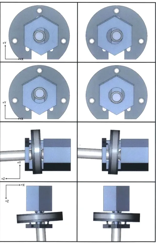
Prior to the functional requirements of Section 2.2 being established, an ampoule-motor interface with similar functionality to the final SAQR was designed. While the purpose of this adapter was not to interface the InjexTM[1] ampoule to the motor, but rather a custom fabricated ampoule, many of the same problems had to be addressed. This adapter is shown in Figure 2-5, Figure 2-6, and Figure 2-7. In this case, the ampoule interface was taken to be a ball end with a slender neck, as seen in Figure 2-7. The adapter is integrated into a pocket machined on the front of the coil former. The internals of the adapter are retained within the pocket by a stainless steel cover, which is bolted to the former with M2 machine screws. The adapter itself consists of two moving components (the retainer and retainer housing) with a spring and a shoulder bolt for actuation. The spring keeps the adapter in the locked position at all time, as seen in Figure 2-7a. When the shoulder bolt, which also acts as an alignment pin for the coil former is pressed radial inwards toward the central axis of the coil, the retainer and retainer housing move downwards to compress the spring and also release the piston, as shown in Figure 2-7b.
The axial force transfer between coil and piston takes two paths, depending on whether load is positive or negative. If load is positive, the ball end of the piston presses directly on the datum plane of the coil. If the load is negative, the ball end of the ampoule presses against the retainer, which presses against the stainless steel cover, which pulls against the machine screws, which in turn pull on the coil former. Though the maximum negative load during normal use is only 10 N, the components were designed to withstand full loading (300 N) in reverse. This was primarily achieved by using high strength materials. A material comparison was done on various high strength materials, with preference given to corrosion resistant materials that allow for sterilization of the entire device. The retainer and cover were designed to be made of 301 Full Hard stainless steel (301 FH), as it is available in precision sheet thickness, has a very high yield strength
(~
0.965 GPa) and canShoulder Bolt Coil Former Retainer Housing Retainer Cover Spring
Figure 2-5: An exploded view of the integrated SAQR adapter design, with all components labeled. The coordinate system used throughout the discussions of the SAQR adapter is also shown.
Locked State, No Piston
Unlocked State, Piston
Figure 2-6: The integrated SAQR adapter in locked and unlocked states. The cover is translucent to show the retainer and its housing in both states. The piston is included in the unlocked state to show its mating features and its relative size. The piston is 4 mm in diameter.
Figure 2-7: Cross section of the integrated SAQR adapter in locked and unlocked states, with the piston engaged with the adapter. The illus-trations labeled A show the adapter in the locked state, with the spring uncompressed. The illustrations labeled B show the adapter in the un-locked state, with the piston still inserted, and the spring in the com-pressed state. The datum plane of the coil former, labeled here as C, is shown in illustration A, with the piston located against it
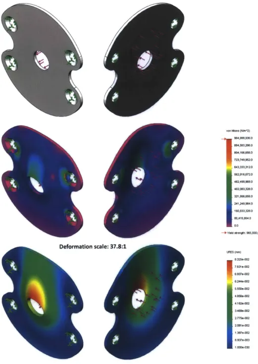
readily be steralized via autoclave. A basic Finite Element Analysis of the retainer and cover were conducted using SolidWorks Simulation. The results are shown in Figure 2-8 and Figure 2-9. For the cover analysis, the faces which meet the M2 screws were assumed fix, and the area where the retainer meets the cover was loaded uniformly with 300 N of force. A set of highly compliant flexures were added to the retainer model to satisfy SolidWorks Simulation constraint requirements. The end of the flexures were defined as fixed, while the desired sliding constraint was given to the actual component, with the portion behind the hole in the cover defined as a free surface. Normal forces were applied'to the retainer faces which result in a net force of 300 N in +Z. As can be seen, the retainer and cover are capable of bearing the full 300 N load in reverse, should the controller fail and apply full power in reverse. The combined predicted displacement of the cover and retainer as also less than 0.09 mm in the axial direction, which would result in volume disparity of less than 0.1 1pL3.
To compensate for radial misalignment of the coil and ampoule, the retainer floats inside of the retainer housing. The retainer can move radially relative to the housing, as well as rotate slightly, as shown in Figure 2-10. While this floating action compen-sates for tX misalignments (see Figure 2-10), it inherently cannot compensate for Y misalignment, as the retainer housing must be capable of pushing the retainer in the +Y direction. If a +Y displaced piston can be fully seated in the retainer, then a -Y displaced piston would seat fully prior to the housing's end of travel. The spring would then apply a +Y load on the piston, nullifying the self-aligning affect. As such, the retention slot on the retainer is elongated such that the piston can be engaged without being fully seated, as shown in Figure 2-11. In this case, a piston displaced to the extreme in +Y seats at the beginning of the retention slot, while a piston diplaced to the extreme in -Y seats at the end of the retention slot. Since radial displacement can be a combination of X and Y displacement, the retainer has the ability to rotate in its housing to aid in aligning the retention slot with the neck of the piston. Angular misalignment is compensated for by the ball end of the piston, as shown in Figure 2-11. Since the end has effectively infinite symmetry, angular
3
assuming a cross sectional area of 1 x 10- in2, as seen on the InjexTM[1] ampoules
von Mims (Nn'2) 964,999,936.0 804,83,296.0 804,16SA M.0 723,749,%52.0 643,333,3120
I562,6972.0
482.499,988.0 402A03,3280 321,6W,856.0 241,249,984.0 160,833,328.0 80,4164660 0,0 -IYIld * n0 9650000000 Deformation scale: 37.8:1 uMS (MM) 8I325-002 7.61e-002 6.937e-002 6244o-002 4.859e-002 41620-002 35.0e-002 27759-002 2.081e-002 1 397e-002 8937e-003 1 000-=03Figure 2-8: Basic finite element analysis of the integrated SAQR cover. The top portion of this figure shows the undeformed fixturing and loading assumptions of the cover. The resulting von Mises stress is shown in the middle, with a deformation scale of 37.8. The lowest safety factor is
1.13 and occurs at the stress risers near the head of the screws. The deformation is shown on the bottom, with a scale of 37.8, and reaches
von--? (N 2) 964,P9S,926.8 884,883,298.8 804,188,6560 723,749,952.0 643,333,32. 582,916,6728 482,499,959.0 402,893,328.0 321 86,6560 241,249,984.0 15,833,328.0 O5,416,664.0 -4Yid *mr t: 9N,00,0000.0 UZ (MM) 5.102.OW 4.5336)03 3.964e003 3 3940-3 2.9206-953 2.256@-=93 1.870-403 1.1170-953 4810-004 .2.116a-005 -5.9040-004 -1.160e-003 -1.7290-003
Figure 2-9: Basic finite element analysis of the integrated SAQR retainer. The top portion of this figure shows the undeformed fixturing and loading assumptions of the cover. The resulting von Mises stress is shown in the middle, with a true deformation scale. The lowest safety factor is 0.85 and occurs at the bottom of the retention slot. Slight localized yielding is undesirable, but acceptable for this worst case scenario. The +Z deformation is shown on the bottom, and reaches 5.1 pm at the edge of the retention slot.
42
Figure 2-10: An illustration of X displacement and rotation of the inte-grated SAQR retainer, showing how the design handles misalignment of the piston relative to the coil former.
misalignments are treated simply as radial misalignments, so long as the neck of the piston does not interfere with the retainer (this happens at ~25', which is much larger than necessary).
Unfortunately, this design has a number of shortcomings. The most substantial of these, given the motivations of the SAQR adapter listed in Section 2.1, is that a custom piston is required. From a robustness standpoint, however, much remains unresolved. While a custom piston could be fabricated, no piston would be perfect, and the integrated design in its current form does not contain a system to compensate for this. If the ball end of the piston were too small, axial play between the coil and piston would result. If the ball end were too large, interference between the retainer and piston would result, and the +Y force needed to lock the adapter would be much greater. It would be very likely that the spring could not provide the requisite force. In such a case, the user would not be immediately aware of this, and an ejection without proper piston-coil coupling could be performed. Additionally, from the perspective of scalability, an integrated adapter such as the one proposed here
Figure 2-11: An illustration of Y and angular misalignment of the inte-grated SAQR piston. The top image shows the piston at the extreme +Y
position, at the edge of the retainer. The middle image shows the piston at the extreme -Y position, near the bottom of the retainer. The bottom image shows the piston at an extreme angle, utilizing the symmetry of piston end to achieve the same retention without added interference.
44
limits the style of piston interface dramatically. This problem is also relevant in the current research device, as the ability to switch piston interfaces without fabricating a new coil former/coil assembly each time is critical. As such, an alternative approach was proposed, as explained in Section 2.3.2.
2.3.2
A Flexure-Based SAQR Adapter
When the functional requirements for the SAQR in Section 2.2 became more explicitly defined, a design which attempted to address the shortcomings of the integrated de-sign of Section 2.3.1 arose. Initially, a dede-sign which simply externalized the integrated design and changed some interface dimensions to comply with the InjexTM[1] piston features was considered. Unfortunately, this would result in an adapter roughly the diameter of the coil former, which would then be mounted to the front of the coil former. This was unacceptable, as the front plate which holds the ampoule is approx-imately the same diameter as the former; this means anything that extends beyond the coil former must be smaller in diameter such that it can fit within the front plate, or stroke must be reduced. Since stroke could not be compromised because of its direct effect on deliverable drug volume, an alternative approach had to be taken.
To resolve the issue of size, it seemed that rearranging the components of the integrated adapter could aid in packaging. Since radial space was the primary limi-tation, but axial space was readily available, packaging more components along the axis of the coil former was a natural approach. The main consumers of radial space in the integrated design are the return spring which engages the retainer with the piston, and the components that prevent the retainer from moving axially: i.e. the fasteners which hold the stainless steel cover, or a snap ring which could serve as an alternative method. The return spring can be replaced with cantilevered beam flex-ures that bend through small angles, allowing radial motion of the retainer through largely axial packaging, as illustrated in Figure 2-12. The cover and its fasteners can be eliminated by changing the way the retainer is constrained to its path. The most apparent way to do this is to use flexures to guide the retainer, rather than sliding surfaces, as illustrated in Figure 2-13.
Unlocked
+Z
iiner Release Pito
Flexure
Figure 2-12: A schematic of a flexure-based SAQR release mechanism, in the locked and unlocked state. These flexures package the release spring
in an axial format, reducing the radial size of the adapter.
Figure 2-13: A schematic of a flexure-based SAQR retainer guide, which forces the retainer into the neutral position. These flexures are only required to provide 0.5 mm displacement and elimate the need for a large cover and fasteners, reducing size.
Ret~
75
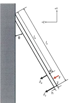
Two possible retainer flexure designs are shown in Figure 14 and Figure 2-15. The first flexure design was derived from the shape of the retention slot in the integrated design, with beam flexures wrapped around the periphery to maximize their length, thus minimizing stiffness. Gaps between the flexures were dictated by the required displacement from nominal (0.5 mm) as well as the capabilities of the in-house wire EDM (electro-discharge machine) [12]. Unfortunately, this design was still 13.4 mm in diameter, without taking into account any mounting features. The flexures also imparted a twisting moment on the retention slot whenever radial displacement occurred.
The second flexure design addressed the size and moment issues of the first by applying reflected symmetry. The flexures were attached to the retention slot across from each other on the centerline of the piston in the locked state. This eliminates any moment. Additionally, to decrease the overall size, the retention slot was short-ened as much as possible. Consequently, all Y misalignment has to be handled by the flexures. To ensure the piston is always in the correct position of the retention slot when it is within the misalignment bounds, the flexures were biased in the +Y direction. This means the retention slot can move 1 mm in the -Y direction and 0 mm in
+Y
from its unloaded state. The size was further reduced by eliminating excess material around the flexures.After some experimentation with flexure layout for the retainer, some exploration was done on the flexure to replace the spring of the integrated SAQR design. The simple beam concept was explored, and the design shown in Figure 2-16 was devised. The slightly tapered beams increase displacement. However, the desired travel of the retainer is so great that a simple beam flexure such as this requires approximately 32 mm of axial length, which is far too great. At this point, an alternative approach to the SAQR problem was sought, which resulted in the floating ring SAQR adapter discussed in Section 2.4.
Figure 2-14: A conceptual design of a potential flexure layout for the retainer.
Figure 2-15: Another conceptual design of a potential flexure layout for the retainer. This design eliminates some excess material and mounts the
Figure 2-16: A conceptual design of a potential release flexure design for the SAQR adapter. The overall length of the flexure is 32 mm when made of 301 FH stainless.
2.4
Design of a Floating Ring SAQR Adapter
2.4.1
The Preload Concept
While the designs discussed in Section 2.3.1 and Section 2.3.2 addressed issues of radial and angular misalignment, they do not sufficiently address issues of piston variability and adapter size. Since the previously proposed designs rely on precise piston geometry, they cease to provide highly repeatable positioning between the piston and coil if this geometry varies. To compensate for variability in the location of piston mating features, axial compliance must be added to the piston retainer. Ideally, the retainer would float freely while the adapter is unlocked, allowing it to fall into place on the piston retaining features. Once locked onto the piston, the retainer would ideally be constrained axially, allowing for misalignment radially and angularly, but restricting axial motion of the piston relative to the coil. Achieving this constraint is complicated by the uncertainty of the retainer's axial position, due to variability in the piston.
One possible solution is to apply an axial preload spring to the retainer once it is engaged with the piston, as shown schematically in Figure 2-17. The spring provides axial compliance, allowing the retainer to be displaced as necessary by the piston, accounting for variations. The spring forces the retainer back towards the datum plane of the adapter, thus locating the back of the piston repeatably each time. The datum plane is the surface which applies the push force directly to the piston, up to 300 N. The pull force is transferred from the piston through the retainer, which loads the preload spring into the fixed reference frame of the adapter body. Since the preload spring is compressed when the adapter is at rest, the force applied by the spring is equal and opposite to the normal force from the datum surface.
As the adapter moves, the requiste force applied to the piston is provided through the differential between the normal force and the preload spring force. When ap-plying a net pull force to the piston, the normal force decreases, while the preload force remains the same. The preload force cannot decrease without the preload spring extending, which would mean the end of the piston must move past the datum plane,
aP,
io
a
a00
Undersized pistonPreload compression springs
Nominal piston Coil Oversized piston
C
Figure 2-17: A schematic of the preload concept for highly repeatable compliant piston coupling. The grooves on the piston are coupled to compression springs mounted rigidly to the coil which allow variation in the piston's axial dimensions while ensuring the end of the piston is located against datum plane C.
which is not possible. The preload force cannot increase without the spring compress-ing further, which can only occur when the piston separates from the datum plane and the normal force goes to zero. As such, so long as the pull force on the piston does not exceed the preload force, the piston does not separate from the datum plane. This principle can be seen in Figure 2-18. The displacement of the preload spring, and thus the preload force, changes with variations between pistons. So long as the minimum preload force, which occurs when the distance between the datum plane and the mating feature of the piston is shortest, is larger than the required pull force, the piston will not separate from the datum plane.
Ideally, the preload force would only be applied once the retainer has completely engaged the piston. Prior to complete engagement, the retainer should float with six degrees of freedom to allow self-alignment. This complicates the preload spring design slightly, as will be discussed in Section 2.4.4.
2.4.2
Floating Ring SAQR Architecture
Before proceeding to explain details of the floating ring SAQR design, it is useful to explain the general architecture and terminology of the system. A simplified version of the SAQR assembly is shown assembled to a simplified version of the current research device in Figure 2-19.
The adapter consists of two main assemblies: the adapter body and the retaining ring. An illustration of the piston insertion and engagement process is shown in Figure 2-20. The piston, with its two molded grooves, is inserted through the body of the adapter while the retaining ring is kept in the release position. Once the piston is fully inserted into the body of the adapter, the retaining ring is pushed radially into its locked state. In the released position, the retaining ring is able to float in six degrees of freedom. During transition, the retaining ring aligns with the grooves on the piston and begins to capture the piston. Once locked, the preload springs, mounted to the adapter body, compress against the retaining ring and load the piston against the body, as discussed in Section 2.4.1. The preload springs act through two points, which in addition to their compliance allows the retaining ring
Preload force= -20 N Normal force= 20 N Net force=0 N Piston at rest Preload force= -20 N Normal force= 10 N Net force=-10 N Piston retracting In contact with coil
Preload force= -20 N Normal force= 0 N Net force=-20 N Piston retracting
Separation from coil begins
+Z
Figure 2-18: A schematic illustrating the forces in piston retraction. As can be seen, so long as the retraction force does not exceed the preload force, the piston cannot move relative to the coil.
Figure 2-19: A version of the floating ring SAQR assembly is shown assembled to a simplified version of the current research device. The hexagonal portion is referred to as the adapter body, while the circular portion around the body is referred to as the retaining ring.