HAL Id: tel-02003494
https://tel.archives-ouvertes.fr/tel-02003494
Submitted on 1 Feb 2019
HAL is a multi-disciplinary open access archive for the deposit and dissemination of sci-entific research documents, whether they are pub-lished or not. The documents may come from teaching and research institutions in France or abroad, or from public or private research centers.
L’archive ouverte pluridisciplinaire HAL, est destinée au dépôt et à la diffusion de documents scientifiques de niveau recherche, publiés ou non, émanant des établissements d’enseignement et de recherche français ou étrangers, des laboratoires publics ou privés.
Cellules solaires organiques à hétérojonction en volume
procédées de solution sur la base de dérivés de
triazatruxene
Tianyan Han
To cite this version:
Tianyan Han. Cellules solaires organiques à hétérojonction en volume procédées de solution sur la base de dérivés de triazatruxene. Electronics. Université de Strasbourg, 2017. English. �NNT : 2017STRAD036�. �tel-02003494�
UNIVERSITÉ DE STRASBOURG
ÉCOLE DOCTORALE Mathématiques, Sciences de l’information et de l’ingénieur
Laboratoire des sciences de l'ingénieur, de l'informatique et de l'imagerie
THÈSE
présentée par :Tianyan HAN
soutenue le : 30 Novembre 2017
pour obtenir le grade de :
Docteur de l’université de Strasbourg
Discipline/ Spécialité
: Physiques des semi-conducteurs et dispositifs organiques
Bulk heterojunction solar cells based on
solution-processed triazatruxene derivatives
THÈSE dirigée par :
M. HEISER Thomas Professeur, université de Strasbourg, France
RAPPORTEURS :
Mme. LUDWIGS Sabine Professeur, université de Stuttgart, Allemagne M. LMIMOUNI Kamal Professeur, université de Lille 1, France
AUTRES MEMBRES DU JURY :
A
CKNOWLEDGEMENTS
I would like to express my gratitude to those who have helped, supported and accompanied me during last three years in ICube.
I would like to sincere thank my supervisor Professor Thomas HEISER for offering me the opportunity to pursue my PhD research in ICube and providing me the guidance and invaluable suggestions throughout my PhD study. I could not finish this thesis without him. He kindly helped me improve my scientific skills and his positive attitude always encouraged me.
I would also like to thank Dr. Patrick Levêque, for sharing his vast knowledge with me, offering valuable help in my writings, and giving enormous support on the charge transport measurements.
Thanks to all my colleagues in ICube: Dr. Sadiara Fall for useful discussions on charge carrier transport and for coffee hours, Dr. Olzhas Ibraikulov for the discussion in scientific and help not only in my work but also in my daily life, Dr. Thomas Regrettier, who finished PhD almost at the same time with me, for his help in capacitance measurements and for all the papers he send to me. As well as Dr. Emilie Steveler for discussions and support.
I also want to thank the technical staff in the lab: Nicolas Zimmermann, Stephan Roques, Sebastian Schmitt, Nicolas Colin and Florent Dietrich for their
kind help and technical support in my work. And Marina Urban for her help in administrative documents.
I am very grateful to Dr. Nicolas Leclerc, who is the head of the chemists in ICPEES, gave me clear explanations for all the questions I have ever asked and guided me to fabricate organic solar cells in the first days of my experiments.
I also want to thank all the colleagues from ICPEES, especially Dr. Ibrahim Bulut, who synthesized all the materials used in this work.
Thanks to Dr. Stephane Méry and Dr. Benoît Heinrich from IPCMS, they offered me enormous help and gave me valuable advice in this thesis work.
Thanks to colleagues from ICS, Dr. Laure Biniek and Dr. Amparo Ruiz-Carretero for the discussions, encouragement and support.
Last but not the least, I would like to thank my parents and my husband Tianyang, who have shown so much understanding and been always there for me.
Tianyan HAN Bonn, Germany 8th January 2018
Tianyan HAN
Bulk heterojunction solar cells
based on solution-processed
triazatruxene derivatives
Résumé
La conception de cellules solaires organiques de type hétérojonction en volume a été proposée pour la première fois en 1990. Ces dispositifs sont composés d’un mélange de polymères conjugués, donneurs d’électrons, et de fullerènes, accepteur d’électrons, et ont pour la première fois permis d’atteindre un rendement de conversion énergétique significatif (de l’ordre de 2%) avec des semi-conducteurs organiques. Dans ce contexte, cette thèse a porté sur l'étude approfondie d’une série de molécules donneurs d’électrons de forme d’haltère, dont le groupement planaire est l’unité triazatruxène (TAT) et le cœur déficient en électrons le thienopyrroledione (TPD). Les molécules de cette série se différencient par la nature des chaînes alkyles, attachées à l’unité centrale et aux unités TAT. Plus précisément, la relation entre la nature des chaînes latérales et les propriétés moléculaires et thermiques de ces molécules en forme d’haltère ont été étudiées en détail. L'impact des chaînes alkyles sur la morphologie en film mince à l’échelle nanométrique a également été étudié. Afin de mieux comprendre l’influence de la microstructure des films minces (constitués soit uniquement des molécules donneuses soit de mélanges molécules/fullerènes), le transport de charge dans le plan du film et perpendiculairement au plan ont été mesurées en fonction de la phase (amorphe, cristalline, …) du matériau. Des cellules solaires BHJ en mélange avec le dérivé de fullerène ont également été réalisées.
Mot-clé : cellules solaires organiques, transport de charges, semi-conducteurs organiques, transistors
organiques à effet de champ, diodes à courant limité à charge spatiale
Résumé en anglais
The prospective conception of electron-donor/electron-acceptor (D/A) bulk heterojunction solar cells was first reported in 1990s, which blended the semiconducting polymer with fullerene derivatives, enhancing the power conversion efficiency. Since then, interests on this domain has been increasing continuously, and the efficiencies of BHJ solar cells have been increased dramatically. In this context, this thesis focuses on the study of a series of dumbbell-shaped small molecule donors, based on a highly planar unit called triazatruxene. The only difference between those molecules is the side-chains attached to central units and TAT units. As a consequence, the relationship between side chains nature and optoelectronic and structural properties of our TAT-based dumbbell-shaped molecular architecture will be investigated in detail. The impact of the alkyl chains on the molecular and thin film properties was also studied, with a particular emphasis put on microstructure and charge transport aspects. In-plane and out-of-plane charge carrier transport, with pure molecules and blend with fullerene, are measured in different systems. BHJ solar cells in blend with fullerene derivatives were also realized.
Keywords: organic solar cells, charge transport, organic semiconductors, organic field-effect
Contents
Contents ... 1
List of variables and abbreviations ... 5
CHAPTER 1 Introduction ... 9
1.1 General introduction ... 9
1.2 The project ORION ... 11
1.3 Thesis structure ... 13
CHAPTER 2 Scientific Background ... 14
2.1 Organic semiconductors ... 14
2.1.1 Origin of semiconducting behavior ... 15
2.1.1.1 Electronic property ... 15
2.1.1.2 Absorption property ... 16
2.1.2 Different types of organic semiconductors ... 18
2.2 Operating principles of organic solar cells ... 19
2.2.1 Light absorption and exciton generation ... 20
2.2.2 Exciton diffusion and dissociation ... 21
2.2.3 Charge transport ... 22
2.2.4 Charge-carrier recombination ... 24
2.2.5 Charge extraction ... 25
2.3.1 Device structures ... 27
2.3.2 Active layer architectures ... 28
2.3.2.1 Single layer structure ... 28
2.3.2.2 Bilayer structure ... 28
2.3.2.3 Bulk heterojunction structure ... 29
2.4 Characteristics of organic solar cells ... 30
2.5 Methods for improving the performance ... 31
CHAPTER 3 State-of-the-art of soluble molecular donors ... 33
3.1 Design strategy of small molecule donors ... 33
3.2 Triazatruxene units for molecule donors ... 37
3.3 Thesis in context ... 40
CHAPTER 4 Materials & Experimental Methods ... 41
4.1 Materials and substrates ... 42
4.2 Experimental methods ... 43
4.2.1 Molecular & bulk material properties ... 43
4.2.1.1 Ultraviolet-visible spectroscopy ... 43
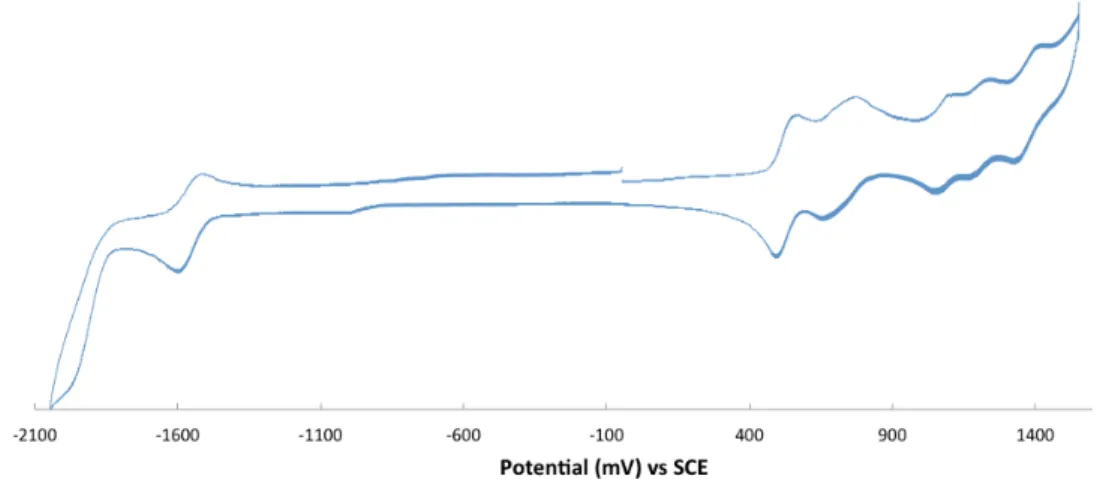
4.2.1.2 Cyclic voltammetry ... 45
4.2.1.3 Differential scanning calorimetry ... 46
4.2.1.4 Small-angle X-ray scattering ... 46
4.2.2 Thin film morphology ... 47
4.2.2.1 Atomic force microscopy ... 47
4.2.2.2 Grazing-Incidence wide-angle X-ray scattering ... 49
4.2.3 Charge transport measurement ... 49
4.2.3.1 Organic field-effect transistors ... 50
4.2.3.2 Space-charge-limited-current diodes ... 54
4.2.4 Photovoltaic properties: organic solar cells ... 57
4.2.4.1 Organic solar cell device elaboration ... 57
4.2.4.2 Solar cells characterization ... 59
CHAPTER 5 Results: Molecular & bulk material properties ... 60
5.2 Optical property: UV-visible spectroscopy ... 62
5.3 Thermal properties: Differential Scanning Calorimetry ... 64
5.4 Structural properties: Small Angle X-ray Scattering ... 65
5.5 Conclusion ... 68
CHAPTER 6 Results: Charge transport measurements ... 69
6.1 Mobilities of TPD-TAT molecules ... 69
6.1.1 In-plane mobility measured by OFETs ... 69
6.1.1.1 As-deposited mobilities ... 69
6.1.1.2 Crystalline state mobilities ... 71
6.1.1.3 Contact resistance ... 72
6.1.2 Out-of-plane mobility measured by SCLC devices ... 74
6.1.2.1 As-deposited mobilities ... 74
6.1.2.2 Crystalline & nematic state mobilities ... 78
6.1.2.3 Corrective factor on thin films with high roughness ... 80
6.1.2.4 Sandwich structural devices with an encapsulated active layer ... 84
6.1.3 Conclusion: charge transport for TPD-TAT molecules ... 87
6.2 Temperature dependent charge transport of TPDC8-TATC8 ... 87
6.2.1 OFET mobilities ... 87
6.2.2 SCLC mobilities ... 89
6.2.2.1 Standard structural devices ... 89
6.2.2.2 Sandwiched structural devices ... 90
6.2.3 Conclusion: temperature dependent charge transport ... 92
CHAPTER 7 Results: Photovoltaic properties ... 93
7.1 Optimum conditions ... 94
7.2 Photovoltaic performances ... 98
7.3 Conclusion ... 100
CHAPTER 8 Results: Thin-film morphology ... 102
8.1 GIWAXS measurements ... 103
8.1.2 TPDC8-TATC8:PC71BM blend films with various weight ratios ... 105
8.1.3 PEDOT:PSS/TPDC8-TATC8 films ... 108
8.1.4 HMDS/TPDC8-TATC8 films ... 110
8.2 AFM measurements ... 112
8.2.1 TPD-TAT:PC71BM blend films ... 112
8.2.2 Pedot:PSS/TPD-TATC8 films ... 113
8.2.3 HMDS/TPDC8-TATC8 films ... 116
8.2.4 Conductive-AFM measurement on TPDC8-TATC8 films ... 118
8.3 Conclusion ... 122
CHAPTER 9 Conclusion ... 123
List of variables and
abbreviations
A Electron acceptor
Abs Absorption
A/D Acceptor/Donor Interface A:D Donor:Acceptor mixture AFM Atomic Force Microscopy
Ag Silver
Al Aluminum
ANR Agence National de la Recherche
Au Gold
AM1.5G The global standard spectrum BHJ Bulk heterojunction
BODIPY Bore-dipyromethene
C60 Fullerene-60
C-AFM Conductive-Atomic Force Microscopy Ci Capacitance of gate dielectric in OFET
CV Cyclic Voltammetry
D Electron donor
Dcol Lateral spacing of TAT columns
DIO 1,8-diiodooctane
DSC Differential Scanning Calorimetry DOS Density of states
Ea Activation energy EA Electron affinity Eg Band gap energy
Eox Potential of oxidation
Ered Potential of reduction
ETL Electron Transport Layer
FF Fill Factor
GIWAXS Grazing Incidence Wide-angle X-ray Scattering
h Plank constant
HTL Hole Transport Layer HMDS Hexamethyldisilazane
HOMO Highest Occupied Molecular Orbital Ids Drain current
LD Exciton diffusion length IP Ionization potential ITO Indium Tin Oxide
J Current density
Jm Current density of point of maximum power
Jsc Short circuit current density
k Boltzmann constant
L Thickness of active layer
LUMO Lowest Unoccupied Molecular Orbital MoO3 Molybdenum trioxide
oDCB Orth-dichlorobenzene
OFET Organic Field Effect Transistor p0 Charge density
P3HT Poly(3-hexylthiophene)
PCBM [6,6]-phenyl-C61-butyric acid methyl ester PCE Power Conversion Efficiency
Pin Power of incident light
Pm Point of maximum power
RC Contact resistance
Rch Channel resistance
Rtotal Total resistance
S Surface of single solar cell SAXS Small-Angle X-ray Scattering SCLC Space-Charge-Limited-Current
Si Silicon
SiO2 Silicon oxide
SVA Solvent vapor annealing
T Temperature
TAT Triazatruxene
Tiso Temperature of isotropic state
TLM Transfer Line Method
UV Ultra-Violet
Vds Drain voltage
Vgs Gate voltage
Vm Voltage of point of maximum power
Vth Threshold voltage
Voc Open circuit voltage
W Channel width
ZnO Zinc oxide
!0 Vacuum permittivity
!r Relative permittivity
" Power Conversion Efficiency
$ Wavelength
% Charge carrier mobility
%0 Mobility at infinite temperature
%lin Linear mobility of OFET
%sat Saturation mobility of OFET
& Conductivity ' Corrective factor
CHAPTER 1
Introduction
1.1 General introduction
Fast economy development, along with the explosive growth of population, has led to a huge energy demand. The International Energy Agency (IEA) reported that in 2014 the total final consumption by fuel was 9425 Mtoea. Among all the energy sources, fossil fuels like oil, natural gas and coal accountfor 66.4 %1. The release of greenhouse gases attributed to the over-consumption of fossil fuels has been considered as one of the main causes of global warming and climate change. In addition, fossil fuels are finite resources, once we use them up, the world will fall into crisis. Nuclear power, another widely used energy source, can reduce carbon emission, however, it requires very careful management of the nuclear plant and nuclear waste, to avoid severe threats to human life. In 2011, the nuclear disaster in Fukushima has led to over 100,000 people evacuated from their hometowns and tons of contaminated water flowing into the Pacific Ocean. Even today, six years after the accident, impacts of nuclear waste still
a
CHAPTER 1.INTRODUCTION
remain in the east Japan. Therefore, tremendous efforts have been devoted to the development and employment of clean and renewable energy technologies, such as solar energy, wind power, hydropower and geothermal energy, etc.
Solar energy is an attractive alternative energy source, because it converts electricity directly by using solar cells, without either producing greenhouse gases or requesting huge power plants. Another advantage of using solar energy is that, the amount of energy provided by the sun per hour to the earth, satisfies the human uses for a whole year.
The process that generates electricity by absorbing light is called photovoltaic effect and was first observed by Alexandre-Edmond Becquerel in 18392. However, the first useable solar cell was fabricated at Bell’s lab only in 19543. Since then, more and more researchers put their efforts into the photovoltaic technology, and designed many types of solar cells, such as silicon, perovskite, dye sensitized, and organic cells. These solar cells can be divided into two catalogues: inorganic and organic. The current solar cell industry is dominated by inorganic solar cells, especially silicon-based solar cells. They have already reached a power conversion efficiency (PCE) of 34 % (GaAs thin film cell), which is the highest efficiency for single-junction terrestrial solar cells to date4. However, electricity supply by inorganic solar cells is still limited by their prohibitive prices, rigidity and fragility drawbacks.
As compared to inorganic solar cells, the organic solar cells, which are relatively new, possess several advantages. First of all, organic semiconductors are inexpensive and can be processed by printing, which further lowers the fabrication cost. In addition, the light-weight, semi-transparency and flexibility suit them more than conventional silicon solar cells to some applications, such as portable cellphone modules, and those where the cells are needed to be attached to windows or curved surfaces, etc.
There are several different types of organic semiconductors among which the π-conjugated polymers are the most widely investigated ones. They were first synthesized by Hideki Shirakawa, Alan G. MacDiarmid and Alan J. Heeger in 1977, three winners of the Nobel Prize in Chemistry in 20005. In 1995, Alan J.
CHAPTER 1. INTRODUCTION
Heeger reported a prospective conception of the so-called electron-donor/electron-acceptor (D/A) bulk heterojunction, which blends semiconducting polymers with C60 (buckminsterfullerene)or its functionalized
derivatives, enhancing the efficiency dramatically6. Through efforts into the molecular design, processing techniques enhancement, morphology control and device architecture improvement in the last two decades, polymer-based solar cells have achieved a PCE over 13 % for laboratory single-junction cells7.
Compared to polymers, π-conjugated small molecules are also promising for the photovoltaic technology. The PCE of small molecule solar cells has been increasing continuously over the last decade and has recently reached the benchmark value of 11% with a single D/A bulk heterojunction (BHJ)8,9. Although the solar cells based on solution-processed small molecules are still less efficient than polymer-based cells, they in principle have several distinctive advantages, such as better control of the molecular structure, easier purification and accordingly lower batch-to-batch variations. Optimization of the chemical structure of the photon absorbing molecules has been a key to this successful endeavor.
1.2 The project ORION
This thesis focuses on the photovoltaic application of soluble small molecules, and it is a part of the project ORION, which was co-funded by the Agence Nationale de la Recherche (ANR) and the Région Alsace. The name ORION stands for <efficient sOluble small molecules foR photovoltaIc applicatiONs>. This multidisciplinary project is being realized by the collaboration of different groups. The group of N. Leclerc from the ICPEESb designed and synthesized all the small molecules investigated in this thesis. Dr. B. Heinrich from the IPCMSc
b
Institut de Chimie et Procédés pour l’Energie, l’Environnement et la Santé, Strasbourg, France
c
CHAPTER 1.INTRODUCTION
worked on structure analysis using Grazing-incidence wide angle X-Ray scattering (GIWAXS). And the group of T. Heiser from the ICubed is specialized in the elaboration and characterization of organic photovoltaic devices.
The objective of the project ORION is to improve the efficiency and the stability of organic solar cells by using bore-dipyromethene (BODIPY) and triazatruxene (TAT) derivatives as electron-donor material (shown in Figure 1-1). The BODIPY derivatives exhibit very high molar extinction coefficients and easily modifiable absorption spectra, which allow efficient photon absorption. And the TAT units exhibit both an optimal solubility due to the alkylation of indole, and a high planarity enabling efficient π-π stacking. In order to obtain a high efficiency, good solubility, wide absorption spectra, matched energy levels and efficient charge transport are essential features for organic semiconductors. Both BODIPY and TAT have been used as constituents of organic semiconductors for photovoltaic applications, and PCE values above 5% have already been obtained with bulk heterojunction devices, and we expect a PCE up to 9 % under optimized conditions10–12. Another goal of this project has been to understand the main factors that limit the efficiency of BODIPY and TAT platforms and to find ways to circumvent them.
As a part of this project, the objective of my thesis work is to improve the efficiency of TAT based small molecules solar cells through the investigation on their molecular structures and charge carrier transport, and understanding the relationships between the molecular structure and the molecular opto-electronic properties. Therefore, a series of TAT-based molecule donors with specific chemical structures (so-called dumbbell-shaped molecules) are in-depth studied. Their molecular and bulk material properties, thin-film properties, charge carrier transport and their applications in bulk heterojunction solar cells have been investigated. Particularly, the charge carrier
d
CHAPTER 1. INTRODUCTION
transport has been studied in detail, since it is a key factor limiting the performance of photovoltaic devices.
Figure 1-1 Chemical formula of BODIPY and TAT.
1.3 Thesis structure
Chapter 2 introduces the scientific background of organic semiconductors and organic solar cells. A detailed literature review is presented and key factors that influence the performance of organic solar cells are discussed.
In Chapter 3, a state-of-art of soluble electron donor small molecules is presented.
Chapter 4 details the molecules and experimental techniques used in this work.
Chapters 5 to 8 report the experimental results including molecular and bulk material properties, thin-film, charge transport and photovoltaic properties.
CHAPTER 2
Scientific Background
This chapter will focus on the introduction of organic semiconductors and on the operation principles of organic solar cells. First, the physics of organic semiconductors are briefly introduced. The next section presents the detailed processes that converts solar energy into electrical energy. Different solar cell device structures are described as well. Then the characterization of organic solar cells and main parameters are recited. The chapter ends with presenting several methods that could promote the performance of the organic solar cells.
2.1 Organic semiconductors
The term “organic semiconductor” refers to organic materials that exhibit semiconducting behaviors. The first studies on organic semiconductors date bake to the early 20th century, when the photoconductivity of anthracene crystals was investigated13. Later, electroluminescence was discovered in the 1960’s, which encouraged many researchers to investigate molecular crystals. In the 1970’s, another important class of organic semiconductors, conjugated polymers, was successfully synthesized14. However, reasonably efficient photovoltaic performances could not be achieved until the demonstration of
CHAPTER 2. SCIENTIFIC BACKGROUND
bulk heterojunction solar cells that incorporated donor and electron-acceptor materials in the 1990s6.
The driving force to study devices based on organic materials comes from potential advantages over silicon or other traditional semiconductors: organic semiconductor devices can be fabricated with bottom-up approaches instead of top-down methods, and open the possibility to produce devices with reduced costs. Moreover, as the physical and electronic properties of organic semiconductors depend on factors like conjugation length or the presence of electron-donating or withdrawing groups, their optoelectronic properties can be tuned by chemical methods: the researchers can design and synthesize new organic semiconductors with desired properties 15,16.
2.1.1 Origin of semiconducting behavior
2.1.1.1 Electronic property
Organic semiconductors are also called π-conjugated materials, because their electronic and optical properties are caused by the π-orbitals of sp2-hybridized carbon atoms. One carbon atom has six electrons, its ground-state electron configuration expresses as 1s22p22s2, where s and p represent the atomic subshells. The sp2-hybridization leads to double covalent bonds between carbon atoms. In this case, three sp2-orbitals are formed by mixing 2s with 2px and 2py orbitals, while one pz-orbital remains unchanged. The three sp2-orbitals are co-planar and point towards the corners of a triangle at an angle of 120°. The overlap of the sp2-orbitals of two neighboring atoms forms a σ-bond. And the electrons in σ-bonds are localized along the axes bridging both atoms. One the other hand, the overlap of the remaining pz-orbitals lead to delocalized molecular orbitals or bonds. An electron in this state is referred to as π-electron (illustrated in Figure 2-1a).
The distance between two neighboring atoms (in one π-conjugated molecule) changes periodically by a few percent due to the periodic distortion of molecular bond length. This situation is represented as an alternation between single and double bonds (as shown in Figure 2-1b), whereas an overlap of the π-orbitals
CHAPTER 2. SCIENTIFIC BACKGROUND
exists within all neighboring C atoms. Therefore, the conjugation of π-bonds gives rise to delocalized π-electron states that support intramolecular charge transport, and result in high electronic polarizability17.
Figure 2-1: (a) two sp2 hybridized carbon atoms showing overlapping of p orbitals; (b) π-conjugated carbon chain: alternating single and double bonds.
2.1.1.2 Absorption property
According to the molecular orbital (MO) theory, the overlap of two pz-orbitals forms two molecular orbitals: π-orbital and π*-orbital (shown in Figure 2-2). The electrons in the pz orbitals are stabilized by occupying the lower energy π orbitals. In the ground state, the occupied orbitals are also known as bonding orbitals, whereas unoccupied orbitals are known as antibonding orbitals. The bonding orbitals have lower in energy than the antibonding orbitals.
The benzene molecule (C6H6) which includes 6 pz and 18 sp2 hybridized orbitals can be considered as an example. The 6 pz orbitals form three occupied π molecular orbitals and three unoccupied π* molecular orbitals. At the same time, 18 sp2 hybridized orbitals form nine occupied & molecular orbitals and nine unoccupied &* molecular orbitals. All the twelve bonding orbitals are fully occupied by 24 valence electrons (illustrated in Figure 2-2a). For more complex conjugated molecules (like conjugated polymers), the long chain of C atoms lead to more occupied and unoccupied molecular orbitals.
CHAPTER 2. SCIENTIFIC BACKGROUND
In the solid state, the energy bands corresponding to the occupied states are referred to as “Highest Occupied Molecular Orbital (HOMO) band” (or “Valence band”), and those corresponding to the unoccupied molecular orbitals are referred to as “Lowest Unoccupied Molecular Orbital (LUMO) band” (or “Conduction band”) (Figure 2-2b). The HOMO and LUMO bands are characterized by two key parameters: the electron affinity (EA) and the ionization potential (IP). EA is the amount of energy released when an electron transfers from vacuum to the lowest energy level in the conduction band, and IP is defined as the least energy spent to release an electron from the LUMO band. The energy gap between the HOMO and LUMO bands is generally close to the optical energy band gap (Eg), which can be estimated from the optical absorption measurements edge. However, this approximation does not take into account the exciton binding energy (see §2.2.1). Under illumination, photons with energy higher than Eg can be absorbed by exciting electrons from the
LUMO band to the HOMO band. For π-conjugated molecules, Eg is generally
low enough for photons of the visible light to be absorbed (i.e. Eg of an organic semiconductor is typically below 3 eV).
Figure 2-2: Diagram of the molecular orbitals of a π-conjugated molecule. The electron at HOMO will excite to LUMO when it absorbs energy higher than Eg.
CHAPTER 2. SCIENTIFIC BACKGROUND
2.1.2 Different types of organic semiconductors
There are two major classes of organic semiconductors: polymers and small molecules. Generally speaking, small molecules have lower molecular weight than polymers and they are mono-disperse18. At present, polymeric semiconductors are the most widely investigated organic semiconductors and have already achieved over 13% efficiencies7. Solar cells based on solution-processed small molecules lag behind polymer-based solar cells in terms of PCE, but benefit in principle from several distinctive advantageous: better control of the molecular structure, easier purification and therefore lower batch-to-batch variations19–21. Figure 2-3 shows several examples of some important conjugated polymers and small molecular semiconductors.
Organic semiconductors are also often classified into “p-type” and “n-type” based on the relative location of their HOMO and LUMO bands. P-type semiconductors are electron-donor materials (D) and are characterized by relatively high lying LUMO and HOMO levels in comparison to N-type semiconductors.
The currently most widely used electron-acceptors for solar cells, are methyl [6,6]-phenyl-C61-butyrate, also called PC61BM, and [6,6]-phenyl-C71-butyrate,
named PC71BM. Due to the symmetrical shape of C61 fullerene, PC61BM has a
much weaker optical absorption coefficient than PC71BM, Both fullerene
CHAPTER 2. SCIENTIFIC BACKGROUND
Figure 2-3: molecular structures of some prototypes of organic semiconductors.
2.2 Operating principles of organic solar cells
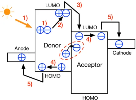
Organic solar cells are composed of a photo-active layer sandwiched between two electrodes with different work functions. The active layer is formed of an electron donor material (D) and an electron acceptor material (A). Both organic semiconductors are differentiated by their respective frontier orbital energy positions: the molecule possessing the lowest ionization potential is referred to as the electron donor (it has a higher HOMO level). On the contrary, the electron-accepting molecule corresponds to the organic semiconductor having the lowest LUMO level and therefore highest electronic affinity. There are several architectures of the active layer, which will be discussed in more detail in section 2.3.
Converting solar energy into electricity includes five steps (summarized in Figure 2-4):
1) Light absorption and exciton generation; 2) Exciton diffusion to donor/acceptor interface; 3) Exciton dissociation;
CHAPTER 2. SCIENTIFIC BACKGROUND
4) Free charge transport or charge recombination; 5) Charge collection at the electrode.
Each process involved in the photovoltaic effect will be discussed in more detail below.
Figure 2-4: Energy level diagram of donor and acceptor in an organic solar cell: six steps of photovoltaic effect.
2.2.1 Light absorption and exciton generation
The first step is to absorb light by the semiconducting layer, leading to the generation of singlet excitons (see Figure 2-4 step 1). The generation of excitons occurs only when photons with energy equal to or higher than the optical band gap of the organic semiconductor are absorbed. As mentioned in section 2.1.1, the energy band gap of organic semiconductors must be below 3 eV to absorb in the visible to near infra-red spectrum. Moreover, according to Shockley-Queisser theory, the optimal energy band gap for single junction solar cells is around 1.3 eV for a theoretical maximum efficiency of 33%24 (shown in Figure 2-5).
CHAPTER 2. SCIENTIFIC BACKGROUND
Figure 2-5: The Shockley-Queisser limit for the efficiency of a solar cell. Adapted from https://en.wikipedia.org/wiki/Shockley–Queisser_limit
Organic semiconductors have often very high absorption coefficients in comparison to inorganic semiconductors and can exceed 105 cm-1. Thus, the photo-active layer can be as thin as 100 – 200 nm and still ensure sufficient light absorption17.
Excitons can be considered as strongly bounded electron-hole pairs, which cannot be separated due to the poor screening of the strong coulombic interactions (low dielectric constant). The excitons can be divided into Wannier-Mott or Frenkel types depending on the properties of medium materials. For the materials with high dielectric constants (inorganic semiconductors, !r > 10), the binding energy is low (in the order of 0.01 eV), such excitons are called Wannier-Mott excitons25. In crystalline silicon for example, the electron-hole binding energy is as low as 14 meV. On the other hand, in the materials of low dielectric constant, such as organic semiconductors, )r is around 3 and the exciton binding
energy is significantly larger, of the order of ~0.3-0.5 eV. This kind of exciton is noted as Frenkel excitons. The thermal energy at room temperature (~26 meV) is insufficient to separate the electron-hole pair.
2.2.2 Exciton diffusion and dissociation
During the short lifetime of photo-generated excitons (in the range of nanoseconds), they may diffuse towards the donor/acceptor interface (see Figure 2-4 step 2), and dissociate into free charges through a charge transfer process at the D/A interface. The transfer process is induced by the energy offsets between the LUMO bands and HOMO bands (HOMOD – HOMOA).
CHAPTER 2. SCIENTIFIC BACKGROUND
When an exciton generated in the D material reaches the D/A interface, it may transfer the excited electron to the acceptor molecule, since the latter provides an energetically favorable environment, whereas the hole remains on the electron donor. This phenomenon is called intermolecular charge transfer (CT). This process is ultrafast, on the order of tens of femtoseconds (fs) and competes efficiently with exciton recombination (that takes place in the ns range). For instance, for the most used donor:acceptor combination Poly(3-hexylthiophene):PC61BM (or P3HT:PC61BM), the charge transfer process has
been reported to take place in less than 120 fs26,27. To guarantee that excitons can reach the D/A interface, the exciton diffusion length LD must be long enough (of the order of the average domain size). LD of organic semiconductors are typically in the range of 5-20 nm28–34. For structurally ordered organic semiconductors,
LD can be very high28. For instance, LD values as high as 68 nm have been reported for copper phthalocyanine (CuPc) derivatives.32
After a successful charge transfer progress, electrons and holes reside on different molecules. However, they are still Coulomb bounded. Although less strongly bounded as the initial exciton, the charge transfer state has to be separated to participate to the photocurrent. To date, the physical origin that allows for the very efficient charge generation observed experimentally, is still under discussion. An in-depth review of charge generation in donor-acceptor blends can be found in reference [35–37].
2.2.3 Charge transport
After the dissociation of excitons, the separated charges can drift or diffuse towards the respective electrodes (see Figure 2-4 step 4). The latter are characterized by their respective work functions, which in turn depend on the Fermi-level (or chemical potential) position in the metal. When a solar cell system is in thermal equilibrium, it tends to get the chemical potentials to be the same across the whole system. Therefore, the system will tend to have some charge redistribution increasing the chemical potential of anode while decreasing the potential of cathode. As a result, a built-in electrical field
CHAPTER 2. SCIENTIFIC BACKGROUND
appears, which will make photo-generated electrons and holes drift towards the cathode and the anode, respectively.
In crystalline inorganic semiconductors with 3D crystal lattice, the atoms are strongly coupled via covalent bonds, that form the conduction band (CB) and valance band (VB). The charge carriers are in delocalized states and their transport is characterized by high mobility values (above 1 cm2/Vs). Such charge carrier transport is called band transport mechanism38,39 and shows a temperature dependence which follows a power law :
% ∝ +,- ./0 1 = 1 … 3 ( 2-1 )
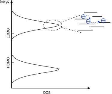
One the other hand, the intermolecular interactions of organic semiconductors are weak van der Waals forces and charge carriers are generally highly localized. The charge carrier transport occurs mostly by hopping between localized states, whose density of the states (DOS) is often described by Gaussian distribution (Figure 2-6).40–42.
The mobility determines the drift velocity of charge carriers under an electric field and is an important factor influencing the performances of solar cells. If the mobilities are too low, electron-hole recombination limits the charge collection and leads to poor power conversion efficiency. The charge carrier mobilities of organic semiconductors are often lower than 10-3 cm-2 V-1 s-1, which is orders of magnitude less than the mobilities of crystalline inorganic semiconductors (1 to 104 cm-2 V-1 s-1)43–45. Instead of a power law temperature dependence, they show an activated behavior which follows the Arrhenius expression:
% ∝ 678(−;<
=+) ( 2-2 )
where Ea is the activation energy and k is the Boltzmann constant.
In organic semiconductors, the hopping transport is highly influenced by the intermolecular interactions and structural order.
CHAPTER 2. SCIENTIFIC BACKGROUND
Figure 2-6: Gaussian Density of States and charge carriers transport by hopping.
2.2.4 Charge-carrier recombination
When charge transport is not efficient, opposite charges may recombine, leading to poor solar cells performances (see Figure 2-4 step 5).
Two different processes of charge-carrier recombination can be distinguished. If the charge transfer state (i.e. the still bound electron-hole pair generated after exciton dissociation) decays to the ground state before dissociation, this is considered as geminate recombination46.
In contrast to geminate recombination, the non-geminate recombination refers to the recombination of electron and holes, which were created by different absorbed photons. The dissociated opposite charges recombine with each other on their way towards the electrodes. The amount of charges in the device depends on the external electrical field, thus, non-geminate recombination strongly depends on the applied voltage due to its impact on the current flow and charge carrier density. The studies on polymer and small molecule based solar cells have shown, that both non-geminate47 and geminate losses48,49 can have a strong impact on the device performance, depending mainly on the photoactive material.
CHAPTER 2. SCIENTIFIC BACKGROUND
Non-geminate recombination of free charge carriers in materials with low mobility can be described with the Langevin recombination rate, established by Paul Langevin in 190346. The recombination rate R is given as:
? = '18 ( 2-3 )
where n, p are the electron and hole concentrations, and ϒ is the Langevin recombination constant.
' =@
!(%A+ % ) ( 2-4 )
where q is the elementary charge, ) represent the effective dielectric constant and %e, %h the mobility of electrons and holes respectively.
Non-geminate recombination is found to be one of the limiting factors of the open-circuit voltage50,51, and the fill factor52 of many solar cells. However, charge recombination is still not fully understood, and further investigations are needed to reduce these losses in solar cells.
2.2.5 Charge extraction
Finally, the photo-generated charges are extracted at the electrodes (see Figure 2-4 step 6).
The free charges will be collected by their respective electrodes to complete the process of solar energy conversion. As presented in the previous section, the electrons will be collected at the cathode and holes will be collected at the anode because of the built-in electrical field. Moreover, at the maximum power point, the electrical field is very low, and carrier diffusion has also a very strong impact on charge collect. Therefore, selective electrodes, which favor either electron transfer or hole transfer, are needed and presented below.
The selection of electrode materials is crucial for charge extraction. The electrode materials must have a proper work-function which needs to be close to the HOMO level of the electron donor material and the LUMO level of the acceptor material, respectively, and avoid the appearance of an energy barrier Φ.
CHAPTER 2. SCIENTIFIC BACKGROUND
A large barrier Φ lowers the extraction rate, leads to charge accumulation near the contact, and results in a low fill factor (FF) and low device performance53,54. Electrode materials for the anode (electron collecting contact) of organic solar cells require low work-function, such as Aluminum (Al), Calcium (Ca). Whereas for the cathode (hole collecting contact), materials with high workfunction like silver (Ag) and gold (Au) are preferred. Bottom electrodes have to be transparent, or at least partly transparent for the good light absorption. Therefore, transparent conducting layers like Indium Tin Oxide (ITO), comprising 90% Indium oxide (In2O3) and 10% Tin oxide (SnO2) with a large
bandgap of 3.7 eV and workfunction of 4.4 – 4.9 eV are used. ITO on glass or plastic substrates, covered by a thin hole transport layer such as Poly(3,4-ethylenedioxythiophene):poly(4-styrenesulfonate) (or PEDOT:PSS), is widely used as electrodes.55,56.
When the solar cell operates at the maximum power point condition, the build-in electric field is significantly reduced, build-increasbuild-ing the risk that the charges are collected at the wrong electrodes.57. To overcome this issue, an electron transport layer (ETL) and/or a hole transport layer (HTL) are used as interlayers between the active layer and the respective electrodes. ETL has a high electron affinity and high electron mobility, it allows electrons to flow across the layer, while holes cannot pass through. On contrast, HTL allows holes to flow through while electrons cannot pass37,58–60. Thus, charge extraction efficiency is increased and bimolecular recombination is reduced at the electrodes. PEDOT:PSS is the most commonly used organic hole transport layer, other materials, such as oxides (i.e. Molybdenum trioxide or MoO3), also have potential for anode interlayer. On the other hand, oxides like Zinc oxide (ZnO) and Titanium oxide (TiOx), and organic interlayer such as 80% ethoxylated polyethylenimine (PEIE)
CHAPTER 2. SCIENTIFIC BACKGROUND
2.3 Device structure and active layer architectures of
organic solar cells
2.3.1 Device structures
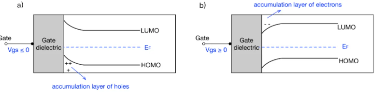
The two most investigated structures of organic solar cells: the standard structure and the inverted structure are shown in Figure 2-7. In the standard structure, electrons are collected at the top electrode and holes are collected at the transparent ITO/glass substrate. Thus, metals with low work-function like Al or Ca/Al, are used as top electrodes. These metals are however easily oxidized in air resulting in poor device stability (in the absence of efficient encapsulation). PEDOT:PSS is commonly used as HTL between ITO and active layer. It blocks electrons and reduces the surface roughness of the ITO layer.
On the other hand, in an inverted structure, electrons are collected at the transparent conducting substrate and holes are collected at the top electrode. For devices with an inverted structure, the anode is on the top, so metals with a high work-function like Ag and Au are used, along with MoO3 as the HTL. In this thesis, we use PEIE, a non-conjugated polymer bearing ionic groups (i.e. a poly-electrolyte), as ETL. It forms a layer of electrical dipoles that reduce the workfunction of ITO and turns ITO into cathode. It also blocks hole transfer efficiently, although the underlying mechanism is still poorly understood.
CHAPTER 2. SCIENTIFIC BACKGROUND
2.3.2 Active layer architectures
The basic structure of a photovoltaic device shown in Figure 2-7 above consists of an active layer sandwiched between two electrodes. In the following part, an overview of possible active layer architectures is presented.
2.3.2.1 Single layer structure
The first organic solar cells consisted of a single polymer layer sandwiched between two electrodes of different work function (simplified schematic shown in Figure 2-8a)61–63. As presented previously, because of the low exciton diffusion length and high binding energy in organic semiconductors, the charge dissociation only occurs at the interfaces between the active layer and the electrodes. As a result, the photovoltaic efficiency is quite low (PCE ~ 0.1 %)64,65.
2.3.2.2 Bilayer structure
The limitation of poor charge dissociation was overcome by Tang’s group in 1986 who introduced the concept of bilayer solar cell. The bilayer heterojunction architecture consists of an electron donor (D) layer and an electron acceptor (A) layer (shown in Figure 2-8b). In this case, exciton dissociation occurs at the D/A interface because of the energy offset of the frontier energy levels between donor and acceptor. At the same time, both electrons and holes diffuse to their respective electrodes in separated domains so that the recombination of the photo-excited charges is reduced. However, the photo-generation of charges is still limited because of the low D/A interface area.
Tang reported a bilayer heterojunction solar cell fabricated from copper phthalocyanine (CuPC) and a perylene tetracarboxylic derivative (PV). The structure of the cell was therefore as follow: ITO/CuPc/PV/Ag. A power conversion efficiency of about 1 % has been achieved with a fill factor as high as 0.6566.
In the early 1990’s, S. N. Sariciftci and A. J. Heeger demonstrated the transfer of ultra-fast photo-inducted electrons (on the order of the picosecond) in the solid state between a donor polymer,
poly[2-methoxy-5-(2-ethylhexyloxy)-1,4-CHAPTER 2. SCIENTIFIC BACKGROUND
phenylenevinylene] (MEH-PPV) and an acceptor fullerene, C60. A two-layer
system involving these two semiconductors allowed them to achieve the efficiency of 0,04%.67 Just a year before, Yoshino et al. demonstrated the same type of phenomenon between poly (3-hexylthiophene) (P3HT) and C6067. P3HT
later became a standard electron-donor material.
2.3.2.3 Bulk heterojunction structure
A bulk heterojunction (BHJ) architecture consists of a blend of donor and acceptor materials for which spontaneous phase separation leads to a nanostructured morphology. Such a blend creates a bi-continuous interpenetrating network of D and A domains. Therefore, the D/A interface is increased and more excitons can be dissociated (Figure 2-8c)6,68. As a result, the power conversion efficiency increases. However, the bulk heterojunction devices are highly sensitive to the morphology of the active layer, which governs charge separation, recombination and transport.
Solution-processed BHJ solar cells were first reported by A. J. Heeger in 1995. They blended MEH-PPV with fullerenes derivative. The PCE increased by more than two orders of magnitude in comparison to a solar cell composed of pure MEH-PPV (single layer solar cell)6. Since this innovative work, the development of new organic semiconductors for BHJ applications has given rise to numerous studies. It is also with this bulk heterojunction architecture that the photovoltaic devices were realized in this thesis.
Figure 2-8: Simplified schematic of (a) single layer, (b) bilayer heterojunction and (c) bulk heterojunction architecture.
CHAPTER 2. SCIENTIFIC BACKGROUND
2.4 Characteristics of organic solar cells
Figure 2-9 shows a current-voltage (J-V) characteristic measured under dark and illumination of a solar cell investigated in this thesis. The main parameter that describes the performance of an organic solar cell is the power conversion efficiency (PCE), denoted as ". " is determined by the ratio between the useful electrical power output Pm and the power of incident light Pin.
" (%) = DE
DF- ( 2-5 )
Figure 2-9 Dark and illuminated J–V characteristics of an organic solar cell investigated in this thesis. The point of maximum power (Pm), as well as the two characteristic parameters,
the short circuit current density Jsc and the open circuit voltage Voc are marked in yellow.
The parameters that influence the efficiency are:
i) Jsc.
Jsc represents the current density obtained by solar cells under short circuit
condition (V= 0 V). It is determined by the amount of charge carriers that are collected at the electrodes, hence, it is also related to the number of photons absorbed in active layer. Optimization of the light absorption can increase Jsc.
Another factor than can influence Jsc is the morphology of the active layer, since
both the surface of D/A interface and the domain size have an impact on the amount of photo-generated charge carriers.
CHAPTER 2. SCIENTIFIC BACKGROUND
ii) Voc.
The theoretical maximum value of Voc is determined by the effective energy gap
(Eg) defined as the difference between the HOMO of the donor (HOMOD) and
the LUMO of the acceptor (LUMOA)69–71. However, the experimental value of Voc
is always lower due to loss mechanisms:
GHI =1
6(;J− ;KHLL) ( 2-6 ) where Eloss is an empirical factor of losses in solar cells. Scharber et al. analyzed the relationship between Voc and Eg for over 26 different BHJ solar cells made of
different donor or acceptor materials, and found that Eloss in BHJ solar cell using fullerene derivatives as acceptor is generally around 0.3 eV72.
iii) FF.
The maximum power point (Pm) of the solar cells corresponds to the voltage
(Vm) and current (Jm) that maximizes electrical power output (DE = GE∙ NE). The solar cell fill factor FF is defined by:
OO = GE∙ NE
GHI∙ NLP
( 2-7 )
Thus, according to equation 2-5 and 2-7 power conversion efficiency " can be expressed as:
" = GHI∙ NLI∙ OO
DF- ( 2-8 )
High charge carrier mobilities and efficient charge extraction are necessary to minimize charge recombination, achieve a high FF, thus a high PCE.
2.5 Methods for improving the performance
To date, the highest efficiency for single junction organic solar cells is around 13 %24,73–75 7 . These promising results are the outcome of the synthesis of new organic materials and of the improved device architectures. In recent years, the better understanding of the solar cell operation mechanisms led to numerous
CHAPTER 2. SCIENTIFIC BACKGROUND
discussions about breaking the limits of the power conversion efficiency. It is important to be aware of the maximum attainable efficiencies in order to find the factors that limit the efficiency and formulate relevant strategies for reaching the limits.
To improve the performance of organic solar cells, several approaches have been suggested. Enhancement of light absorption by increasing further the absorption width of the conjugated molecules is still possible.
Increasing Voc by controlling the LUMO and HOMO energy levels of donor and
acceptor materials is also crucial for improving the PCE.
A better controlled nanomorphology of the BHJ active layer by choosing for instance proper solvents and post-processing methods can improve the efficiencies of the BHJ solar cells as well. Thermal annealing is a common strategy to improve the morphology of BHJ active layer. Another approach is solvent vapor annealing, by placing the solar cell samples in a solvent saturated environment.76–78 Using processing additives, i.e. introducing small amounts of a solvent into the host solvent to solubilize the active materials, is another approach to control the BHJ morphology.
CHAPTER 3
State-of-the-art of soluble
molecular donors
The last two decades have seen remarkable progress in the development of organic bulk heterojunction (BHJ) solar cells. During this period, the power conversion efficiency (PCE) of polymer-based organic solar cells (P-OSC) has reached 13 %7, while small-molecule-based organic solar cells (SM-OSC) exceeds 10%73,74. This rapid progress was made possible through improved molecular design, reformative device architecture and better control of morphology.
In this chapter, I will give a short overview of the design strategies of small molecule donors that have been followed worldwide to improve the efficiency of SM-OSC devices.
3.1 Design strategy of small molecule donors
A most common strategy to design a small molecule donor is to associate electron-rich and electron-deficient moieties, referred to as donor (D) and acceptor (A) units, respectively, along the conjugated backbone in order to tune its frontier orbital energy levels and approach optimum values79–81. As shown in
CHAPTER 3. STATE-OF-THE-ART OF SOLUBLE SMALL MOLECULE DONORS
Figure 3-1, when D and A units are associated together, the new hybrid HOMO level is close to (generally slightly higher than) the HOMO of the D unit while the new LOMO level is close to (or slightly deeper) than the A unit. As a result, the energy band gap can be adjusted.
Figure 3-1: Illustration of the hybridization of energy levels of a conjugated molecule alternating donor (D) and acceptor (A) units.
Generally, these molecules are axisymmetric, that is, donor-acceptor (D-A) structures are symmetric about the central core, such as A-D-A, D-A-D, A-D1-D2-D1-A or D1-A-D2-A-D1 structures. An advantage of these structures is that the optoelectronic and molecular properties can be tuned by varying one of the moieties without changing the overall structure. The symmetry of the structures also assists the molecular self-assembly and often leads to well-developed ordered structures and correspondingly high photovoltaic performance.
The study on oligothiophene based molecule donors by Chen’s group show that adding electron-withdrawing end-groups such as dicyanovinyl82, alkylcyanoacetate or indenedione83 to build A-D-A molecules improves the photovoltaic performance. The highest PCE results were obtained using dicyanovinyl-substituted rhodamine (RCN) as electron-withdrawing group (chemical structures shown in Figure 3-2). The results show that molecules with axisymmetric chemical structures (DRCN5T, DRCN7T, DRCN9T in Figure 3-2) exhibit much higher Jsc values (14-16 mA cm-2) and thus higher PCEs than those
with centrosymmetric chemical structures (DRCN4T, DRCN6T, DRCN8T) (Jsc~11 mA cm-2). Maximum PCE of 10.08 % for DRCN5T and 9.4% for DRCN7T
CHAPTER 3. STATE-OF-THE-ART OF SOLUBLE SMALL MOLECULE DONORS
have been obtained, which are among the highest PCE values for small molecule based BHJ solar cells obtained so far. Moreover, according to morphological investigations of the active layers by transmission electron microscopy (STM) and grazing incidence X-ray diffraction (GIXD), molecules with axisymmetric chemical structures exhibit more well-developed fibrillar networks, which is beneficial for charge carrier transport, and lead to high Jsc and FF84.
Figure 3-2: Chemical structures of DRCN4T - DRCN8T, adapted from Reference [84].
Table 3-1: Average OPV performance parameters for DRCN5T-DRCN9T BHJ devices under the optimized conditions. Adapted from Reference [84].
Molecules Voc (V) Jsc (mA cm-2) FF PCE (%)
DRCN5T 0.92 -15.66 0.68 9.8
DRCN6T 0.92 -11.45 0.58 6.1
DRCN7T 0.90 -14.77 0.68 9.1
DRCN8T 0.86 -10.80 0.68 6.4
DRCN9T 0.81 -13.77 0.68 7.6
Similar work has been done by Zhang et al. to synthesize A-D-A molecule using BDD units with strong electron-withdrawing ability. A quite deep HOMO level of -5.12 eV was obtained, as presented in Chapter 2, Voc equals to the difference
between HOMO level of the donor and the LUMO level of the acceptor, thus a deep HOMO level of the donor material leads to a high Voc. Here, for BDD
based molecules, a Voc as high as 0.96 V has been obtained and a maximum PCE of 9.53 was achieved73.
Another important approach has been to address the molecular self-assembly in solid state by adding highly planar units. The planar units are expected to
CHAPTER 3. STATE-OF-THE-ART OF SOLUBLE SMALL MOLECULE DONORS
increase intermolecular forces and allow a better charge extraction through improved charge carrier mobilities.
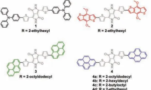
The investigation on the influence of highly planar units in molecule donors has been done first by Lee and co-workers85. They attached different electron-rich end-groups onto an electron-withdrawing core. Those end-groups have varying degrees of planarity (chemical structure shown in Figure 3-3). Molecule 1 has non-planar triphenylamine (TPA) as end-groups, while end-groups of
molecules 2 is benzo[1,2-b;4,5-b’]dithiophene (BDT), which contains a planar
fused ring but has no-coplanar alkoxy substituents. Molecule 3 and 4 has highly planar pyrene end-groups, but the sites of pyrene substituents are different.
Figure 3-3: Chemical structures of molecules with DPP core moiety flanked by different electron-rich end-groups. Adapted from Reference [85].
The average OPV performances of BHJ devices are summarized in Table 3-2, and show that the molecule with highly planar end-groups (molecule 4 in Figure 3-3) have higher PCEs than non-planar end-groups. Because planar end-groups facilitate favorable end-to-end π-π interactions (illustrated in Figure 3-4), hence, charge transport between adjacent molecules and photovoltaic efficiencies are enhanced85.
The comparison of molecule 3 and 4a indicates that the end-group symmetry can also have significant influence on PCE. Further variation of alkyl side chains on the DPP core moiety showed that the side-chains can affect the intermolecular spacing and OPV performance (molecule 4a, 4b and 4c).
CHAPTER 3. STATE-OF-THE-ART OF SOLUBLE SMALL MOLECULE DONORS
Figure 3-4: Illustration of molecular self-assembly through end-to-end π-π stacking. Adapted from Reference [85].
Table 3-2: Average OPV parameters for molecule 1-4. Adapted from Reference [85].
Molecule Voc (V) Jsc (mA cm-2) FF PCE (%)
1 0.73 -4.3 0.31 1.0 2 0.81 -6.2 0.30 1.3 3 0.73 -3.2 0.29 0.7 4a 0.77 -5.7 0.55 2.4 4b 0.76 -8.3 0.58 3.7 4c 0.78 -6.6 0.48 2.4
3.2 Triazatruxene units for molecule donors
The same design strategies are employed to molecule donors investigated in this thesis. In our ORION project,
10,15-dihydro-5H-diindolo-[3,2-a:3’,2’-c]carbazole units, also called triazatruxene (TAT), are used as π-stacking
platform (shown in Figure 3-5).
Figure 3-5: Chemical structure of the triazatruxene (TAT), showing its complete numbering. Functionalized triazatruxene derivatives are interesting organic electronic materials because of their unique optoelectronic properties. The first TAT unit was synthesized by Sweden chemists Jan Bergman and Nils Eklund in 198086,87. It is a C3 symmetric planar π-extended conjugated structure, and can be considered as an overlapping framework of three carbazole units fused together, thus, resulting in an electron-donating unit. The planar character of TAT moieties promotes π-orbital overlapping, leading to a strengthened molecular
CHAPTER 3. STATE-OF-THE-ART OF SOLUBLE SMALL MOLECULE DONORS
stacking behavior and charge transport. In addition to its planarity, the TAT units can also be made highly soluble because of three amine groups (position 5, 10 and 15) that are able to carry alkyl chains. For instance, TATC8 shown in Figure
3-6 is an alkylated triazatruxene unit which has been investigated by Gallego-Gómez et al.88. It can be self-assembled into ordered nanostructures in solution-processed cast films. in addition, face-to-face molecular packing in a columnar crystalline phase provided a significant π-π stacking and therefore good charge transport88.
Figure 3-6: Chemical structure of TATC8.
TAT units can also be functionalized to build more complex molecular architectures (through position 2, 3, 7, 8, 12, or 13), such as star-shaped molecules89–91, dumbbell-shaped molecules11,12,92,93, D-π-A linear molecules92, etc.
Bura et al. reported a series of TAT functionalized D-π-A linear molecules which show large absorption coefficients and fluorescence quantum yields as well as interesting electrochemical properties due to the introduction of TAT units92. Molecules TAT-Bodipy2 in this series reaches a Voc of 0.83 V, Jsc of 3.6 mA/cm2
and the a promising PCE of 0.9 %.
Figure 3-7: Chemical structures of TAT-linked Bodipy derivatives. Adapted from reference [92].
CHAPTER 3. STATE-OF-THE-ART OF SOLUBLE SMALL MOLECULE DONORS
Huaulmé et al. further synthesized a family of star-shaped molecules with TAT as the core and DPP as the branches to broaden the photo-absorption region and reduce the band gap (Figure 3-7).91 All the molecules exhibits strong and wide absorption in the near-UV and visible region of the solar spectra (400 -750 nm), with intramolecular cascade energy transfer enabling photo concentration and fluorescence at approximately 740 nm.
Figure 3-8: Chemical structures of the mono-, bis-, and tris- DPP substituted TAT based star-shaped panchromatic absorbing dyes. Adapted from reference [91].
Our group has previously used TAT units as end-groups attached onto electron acceptor units such as DPP to build dumbbell-shaped molecules11. Both, good planarity and solubility were achieved. The TAT units promoted end-to-end π-π stacking and lead to favorable transport properties. Promising Voc above 0.6 V,
Jsc around 14.6 mA cm-2 and a PCE of 5.3 % were obtained.
Figure 3-9: Chemical structures of TAT based dumbbell-shaped molecules with different central cores.
Moreover, by varying the electron-attracting central moiety, the electrochemical properties could be tuned without changing significantly the chemical
CHAPTER 3. STATE-OF-THE-ART OF SOLUBLE SMALL MOLECULE DONORS
structure. Indeed, a series of dumbbell-shaped molecules, with benzo[2,1,3]-thiadiazole (Btz), pyridal[2,1,3]-benzo[2,1,3]-thiadiazole (Pytz), or thieno[1,2,5]-benzo[2,1,3]-thiadiazole (Ttz) as electron-withdrawing cores, respectively, and triazatruxene end-cappers were investigated.11,12,92,93 The HOMO levels were similar for all the compounds, while the LUMO levels decreased from 3.6 eV (Btz) to 3.8 eV (Pytz), and to -3.9 eV (Ttz), respectively. The relationship between chemical structure and electronic properties remains hard to predict, because a slight change in the molecular assembly can have a strong influence on charge transport and morphology (in particular in a donor/acceptor blend). For instance, the position and nature of alkyl side chains are nowadays well known to strongly impact the structural properties of π-conjugated materials, whether polymers or small molecules94,95, which possibly affects the material optoelectronic properties.
3.3 Thesis in context
To further understand how the presence of alkyl chains on the TAT unit may influence the optoelectronic properties, we have studied in depth a series of TAT-based dumbbell-shaped molecule donors and their behavior in BHJ solar cells. The molecules were based on an identical π-conjugated backbone, made up of a thieno[3,4-c]pyrrole-4,6-dione) (or TPD) central chromophore and two TAT units. A series of molecules with different combinations of side chains were investigated (molecules will be presented in detail in chapter 4). The TPD unit is an electron-withdrawing group that can decrease the FMO energy levels of molecule donors. In addition, the relatively compact and planar structure of TPD could facilitate the electron delocalization and enhance the intermolecular interactions.
In this thesis, the charge transport, microstructure and optoelectronic properties of these molecules have been studied in-depth and the effect of TAT units on molecular organization, charge transport and photovoltaic performances have been explored both, in pure materials and in blends with PCBM.
CHAPTER 4
Materials & Experimental
Methods
A series of organic semiconducting molecular electron donors were investigated in this thesis. In order to understand the material properties as much as possible, different types of experimental techniques were employed. In this chapter, the experimental details of the procedures used throughout this thesis are summarized.
First, a brief description of the materials and substrates will be given. Then the experimental methods for investigating molecular and bulk material properties are presented, followed by the characterization of thin-film morphologies. The next section introduces the in-plane and out-of-plane charge carrier transport measurements. Elaboration procedures and analytical expressions used to extract the carrier mobilities are also detailed. The final section of this chapter presents the elaboration procedures of inverted organic solar cell devices and also the characterization methods.