RESEARCH OUTPUTS / RÉSULTATS DE RECHERCHE
Author(s) - Auteur(s) :
Publication date - Date de publication :
Permanent link - Permalien :
Rights / License - Licence de droit d’auteur :
Bibliothèque Universitaire Moretus Plantin
Dépôt Institutionnel - Portail de la Recherche
researchportal.unamur.be
University of Namur
Integration of Legacy and Heterogeneous Databases
Thiran, Philippe; Hainaut, Jean-Luc
Publication date:
2002
Link to publication
Citation for pulished version (HARVARD):
Thiran, P & Hainaut, JL 2002, Integration of Legacy and Heterogeneous Databases. Institut d'Informatrique -LIBD, Namur.
General rights
Copyright and moral rights for the publications made accessible in the public portal are retained by the authors and/or other copyright owners and it is a condition of accessing publications that users recognise and abide by the legal requirements associated with these rights. • Users may download and print one copy of any publication from the public portal for the purpose of private study or research. • You may not further distribute the material or use it for any profit-making activity or commercial gain
• You may freely distribute the URL identifying the publication in the public portal ?
Take down policy
If you believe that this document breaches copyright please contact us providing details, and we will remove access to the work immediately and investigate your claim.
InterDB Project
Integration of Legacy and
Heterogeneous Databases
Philippe Thiran (report author), Jean-Luc Hainaut (project leader), Stéphane Bodart, Abdelmajid Chougrani,
Arnaud Deflorenne, Olivier Dumoulin, Jean-Marc Hick University of Namur - Institut d’Informatique rue Grandgagnage, 21 z B-5000 Namur (Belgium)
[email protected] - http://www.info.fundp.ac.be/libd
InterDB Project III
Credits
This text is based on the results of the InterDB project supported by the Belgian Région Wal-lonne (Direction Générale des Télécommunications, de la Recherche et de l’Energie).
InterDB Project
The InterDB Project is a research, development and technology transfer programme in data integration engineering, undertaken at the Institute of Informatics of the University of Namur since September 1995. The InterDB project is dedicated to the integration and the in-teroperability of heterogeneous and distributed information systems. It directly profits from research and development results that have been developed in the DB-MAIN research project.
Research Aspects of InterDB
Though some aspects of the databases integration can now be considered as fairly well un-derstood, some complex problems and processes still are unsolved at the present time, despite an increasing interest of the scientific community. Such is the case of semantic recovery and semantic integration. The InterDB project is intended to contribue to solving these problems by concentrating on their database aspects first.
The technical material of InterDB has been described in about ten scientific papers published in the main international conferences and journals since 1995. The basic principles has been decribed in the three papers:
• Ph. Thiran, J-L. Hainaut, S. Bodart, A. Deflorenne, J-M. Hick, "Interoperation of Inde-pendent, Heterogeneous and Distributed Databases. Methodology and CASE Support: the InterDB Approach" in Proceedings of CoopIS'98, IEEE, New York, August 1998. • J-L. Hainaut, Ph. Thiran, J-M. Hick, S. Bodart, A. Deflorenne, "Methodology and CASE
tools for the development of federated databases", International Journal of Cooperative Information Systems, 8(2-3), pp. 169-194, World Scientific, June and September 1999. • Ph. Thiran, J-L. Hainaut, "Wrapper Development for Legacy Data Reuse", in
Procee-dings of WCRE’01, IEEE, Stuttgart, October 2001.
The InterDB approach of the database inegration has been presented in several main interna-tional conferences:
• Main conferences: IFCIS International Conference on Cooperative Information Systems, 1998 New York City; Database and Expert System Applications Conference, 1999 -Florence; International Workshop on Engineering Federated Information Systems, 2000 and 2001 - Dublin and Berlin; and IEEE Working Conference on Reverse Engineering, 2001 - Stuttgart.
• Main foreign universities: EPFL, Magdeburg Universität, Laboratoire d’Informatique de Paris VI, Université de Lyon I, Université de Lausanne and Universiteit van Tilburg.
Development Aspects of InterDB
The scientific material that is developed in research activities is implemented as software and CASE tool components. They transform the research results into practical methods and tech-niques that can be most helpful for practitioners. In that way, the InterDB materials have been used by two joint projects: the Data Migration Project [Delcroix, 2001] and the Administra-tive Database Integration Project (with the City Council of Namur).
Technology Transfer of InterDB
As an academic institution, the University of Namur, and particularly the Institute of Infor-matics, is strongly committed to making knowledge available to as large as possible an audi-ence. Accordingly, the InterDB results are translated into educational materials such as case studies, lectures and training seminars, mainly intended to the industrial partners.
InterDB Team
The InterDB tream comprises research associates: Stéphane Bodart, Abdelmajid Chougrani, Arnaud Deflorenne, Olivier Dumoulin, Jean-Marc Hick and Philippe Thiran. The manage-ment and scientific direction of the InterDB project is carried out by professeur Jean-Luc Hainaut.
The first materials of the InterDB project have been tested and improved by several students: Renaud Denis [Denis, 2002], Bernard Noël [Noel, 2001] and Sybille Radulescu [Radulescu, 2001].
Acknowledgments
We thank Jean-Luc Hainaut for his support, his supervision and his very useful advices. With-out him, nothing would have been possible. We also thank Jean-Marc Hick for his rereading of this report.
À Mon Hélène Philippe
InterDB Project V
Summary
Accessing and managing data from several existing independent databases pose complex problems that can be classified into platform, DMS, location and semantic levels. The plat-form level copes with the fact that databases reside on different brands of hardware, under different operating systems, and interacting through various network protocols. Leveling these differences leads to platform independence. DMS level independence allows program-mers to ignore the technical details of data implementation in a definite family of models. It can also hide the model that the DMS implements by providing a more abstract model. Lo-cation independence isolates the user from knowing where the data reside. Finally, semantic level independence solves the problem of multiple, replicated and conflicting representations of similar facts.
The InterDB project proposes a general architecture, a methodology and a CASE environ-ment intended to address the problem of providing users and programmers with an abstract interface to independent, heterogeneous and distributed databases.
Architecture. The architecture comprises a hierarchy of mediators that dynamically trans-form actual data into a virtual homogeneous database. Each layer of mediators provides a cer-tain kind of independence. DMS independence is provided by wrappers dedicated to each database. Location and semantic independence’s are ensured by a mediator. Finally, platform independence is ensured by both the wrappers and ad hoc middleware such as commercial ORB.
Methodology. Such an architecture involves controlling complex mappings. The problem is complicated by the fact that the databases have been developed independently, and naturally suffer from sever problems of replication and semantic conflicts. In addition, most legacy da-tabases have no documentation any more, just like programs. Recovering the conceptual schemas form an existing database is the main goal of database reverse engineering, an im-portant software engineering that can now be considered mature. Solving the syntactic and semantic conflicts of independent schemas has long been studied in the database realm. How-ever, coping with conceptual schemas form populated databases brings new problems. A complete methodology, encompassing conceptual schema recovery and database integration is provided to practitioners.
Case support. Deriving a common, abstract and conflict-free image of independent databas-es and defining the mappings between the specification layers are complex tasks. Building the wrappers and the mediators are also two complex and error-prone activities. All these pro-cesses are supported by the DB-MAIN CASE tool. This graphical, repository-based, software engineering environment includes, among others, a sophisticated reverse engineering toolkit, schema mapping specification facilities and a generator development environment.
Table of Contents
Chapter 1 - Introduction
Part I: Generic Integration Framework Chapter 2 - Integration Architecture Chapter 3 - Generic Data Model Chapter 4 - Mapping Definition Part II: Wrapper Technology
Chapter 5 - Wrapper Architecture
Chapter 6 - Wrapper Development (Methodology) Chapter 7 - Wrapper Development Support Part III: Mediator Technology
Chapter 8 - Mediator Architecture
Chapter 9 - Mediator Development (Methodology) Chapter 10 - Meditator Development Support References
The InterDB Project (1995-2002) has been supported by the Belgian Région Wallonne
(
Direction Générale des Télécommunications, de la Recherche et de l’Energie) z Report Edition 1.1 z November 2002InterDB Project VII
Detailed Table of Contents
Chapter 1
Introduction... 1
1.1 Introduction ...1
1.2 Problem and Context of InterDB...2
1.2.1 Legacy Data Systems...2
1.2.2 Distribution ...2
1.2.3 Autonomy ...3
1.2.4 Heterogeneity...3
1.2.5 Mediation ...4
1.2.6 Mediation and Legacy Databases ...4
1.2.7 Database Integration ...6
1.3 Scope and Overview...8
1.3.1 Scope...8
1.3.2 Overview...8
Part I - Generic Integration Framework
Chapter 2
Integration Architecture... 13
2.1 Introduction ...13
2.2 Overview of integration architectures ...13
2.2.1 Global Schema Systems...15
2.2.2 Multidatabase Languages ...15 2.2.3 Federated Architecture...16 2.3 InterDB Architecture ...18 2.3.1 Hierarchy Architecture ...18 2.3.2 Component Architecture...19
Chapter 3
Generic Data Model ... 21
3.1 Introduction ...21
3.2 Generic Data Model ...22
3.2.1 Main concepts ...22
3.2.2 Meta concepts ...24
3.3 Federation Data Models ...26
3.3.1 Legacy Data Models ...26
3.3.2 Canonical Data Models...28
3.3.3 Object-oriented Model...30
Chapter 4
Mapping Definition ... 33
4.1 Introduction ...33 4.2 Mapping Baselines ...33 4.3 Definition...34 4.3.1 Reversibility...354.3.2 Structural Analysis of a Transformation...36
4.3.3 Signature of a Transformation ...36
4.3.4 Schema Transformation Sequence...37
4.3.5 Schema Integration ...38
4.4 Some Popular Transformations ...39
4.5 Transformation History ...40 4.5.1 Structure of a History...40 4.5.2 History Subset...41 4.5.3 Independent Histories ...42 4.5.4 Equivalent Histories...42 4.5.5 Minimal History...43 4.6 Model Transformation...44
Part II - Wrapper Technology
Chapter 5
Wrapper Architecture ... 49
5.1 Introduction ...49
5.2 Legacy Data Wrapper Definition ...51
5.2.1 Overview...51
5.2.2 Definition ...51
5.2.3 Functionality ...51
5.2.4 Legacy Issues...52
5.2.5 Motivations and Objectives ...54
5.3 Architecture ...55
5.3.1 General Framework ...55
5.3.2 Wrapper Interface ...57
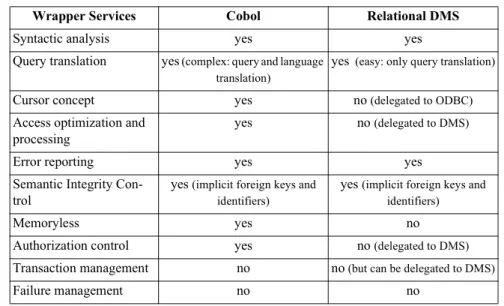
5.4 Wrapper Services...60
InterDB Project IX
5.4.2 Error Reporting ...62
5.4.3 Functionality Emulation ...62
5.4.4 Query Processing ...66
5.4.5 Semantic Integrity Control...70
5.5 InterDB Prototypes ...74 5.5.1 Logical Wrapper ...76 5.5.2 Object Wrapper...80
Chapter 6
Wrapper Development ... 83
6.1 Introduction ...836.2 Wrapper Development Baselines ...84
6.2.1 Observations ...84
6.2.2 Wrapper Dimensions ...84
6.2.3 Wrapper Models and Schemas ...86
6.2.4 Wrapper Mapping ...87
6.2.5 Logical Wrapper Architecture ...88
6.3 Methodology for Logical Wrapper Development ...91
6.3.1 Overview...91
6.3.2 Development Baselines...92
6.3.3 Wrapper Definition ...92
6.3.4 Logical Wrapper Definition...94
6.3.5 Wrapper Packaging...95
6.3.6 Generator Application and Maintenance ...95
6.4 Methodology for Instance Wrapper Generation...95
6.4.1 Data-centered Reverse Engineering...96
6.4.2 Catalog of Implicit Constraints and Constructs...100
6.4.3 Wrapper Schema Definition ...104
6.4.4 Mapping Definition...105
6.5 Methodology for Upper Wrapper Development ...106
Chapter 7
Wrapper Development Support ... 107
7.1 Introduction ...107
7.2 CASE Tool Requirements ...108
7.2.1 General Support ...108
7.2.2 Support of the Data-centered Reverse Engineering...108
7.2.3 Support of the Mapping Definition...109
7.3 DB-MAIN...109
7.3.1 User Interface...109
7.3.3 Voyager 2...111
7.3.4 Transformation Toolkit...112
7.3.5 Text Analysis and Processing ...113
7.3.6 Assistants ...114
7.3.7 History ...118
7.4 InterDB Tools...119
7.4.1 History Analyzer...121
7.4.2 Wrapper Encoders...123
Part III - Mediator Technology
Chapter 8
Mediator Architecture... 127
8.1 Introduction ...127 8.2 Mediator Definition ...127 8.3 Architecture ...129 8.3.1 General Framework ...129 8.3.2 Mediator Interface...130 8.4 Mediator Services...134 8.4.1 Query Analysis ...134 8.4.2 Query Processing ...135 8.4.3 Security Management ...1388.4.4 Global Semantic Integrity Management ...139
8.4.5 Transaction Management...140
8.5 InterDB Prototype ...143
8.5.1 Mediator Architecture...143
8.5.2 Object Mediator and DB-MAIN Repository ...144
8.5.3 Algorithm Principle of the Object Mediator...147
Chapter 9
Mediator Development ... 149
9.1 Introduction ...149
9.2 Framework for Schema Integration...150
9.2.1 Integration Strategies ...151
9.2.2 Pre-integration ...151
9.2.3 Correspondence Identification...153
9.2.4 Schema Integration ...153
9.2.5 Mapping Definition...154
9.3 Schema Integration Issues ...155
XI InterDB Project
9.3.2 Interschema Conflicts ...158
9.4 InterDB Approach ...160
9.4.1 InterDB Principles ...160
9.4.2 Practical InterDB Methodologies ...164
Chapter 10
Mediator Development Support ... 167
10.1 Introduction ...167
10.2 CASE Tool Requirements ...168
10.3 DB-MAIN...169
10.3.1 DB-MAIN Repository ...169
10.3.2 Integration Assistants...170
10.3.3 History ...174
10.4 InterDB Tools...175
10.4.1 InterDB Extension of the DB-MAIN Repository ...175
10.4.2 History Analyzer...181
10.4.3 Java Access to the DB-MAIN Repository...182
Chapter 1
Introduction
In which the reader is introduced to integration of legacy databases by first giving its main issues. The terms legacy, autonomy, heterogeneity and mediation are introduced, and a short overview of the InterDB approach is given.
1.1
Introduction
Most large organizations maintain their data in many distinct independent databases that have been developed at different times on different platforms and DMS (Data Management Sys-tems).
The new economic challenges force enterprises to integrate their functions and therefore their information systems including the databases they are based on. In most cases, these databases cannot be replaced with a unique system, nor even reengineered due to the high financial and organizational costs of such a restructuring. Hence the need for interoperation frameworks that allow the databases to be accessed by users and application programs as if they were a unique homogeneous and consistent database, through an architecture called federated data-bases.
1.2
Problem and Context of InterDB
1.2.1 Legacy Data Systems
The presence of legacy data systems is one of the major obstacles in the use of integrated in-formation.
A legacy IS is any IS that significantly resists modifications and changes. Typically, a legacy IS is big, with millions of lines of code, and more than 10 years old. [Brodie 1995]
Legacy data systems are very large. They are written in old programming language like CO-BOL or PL/1. Such systems are usually mission critical to the day-to-day operation of oper-ation of corporoper-ations and are thus very valuable from a business point of view. However, they are inflexible in nature and expensive to maintain or to change [Bouguettaya,1998]. Legacy data systems must be kept as they are for several reasons [Umar, 1997]. First, they provide vital services that are very risky to disrupt. Second, many users and support staff are trained on how to operate these systems and to use them. Third, many legacy systems are very reliable and perform very well, contrary to the common belief. Fourth, the administrative sup-port of mainframe-based legacy applications (e.g., backup/recovery, change management, se-curity) has matured over the years. Finally, there is some emotional attachment to legacy applications among senior staff because these systems have survived through years of funda-mental changes in business practices and technologies.
However, something must be done about these systems. First, legacy applications are becom-ing increasbecom-ingly expensive to maintain and operate (it takes months to introduce a change). Second, these applications do not satisfy the flexibility and growth requirements of modern organizations. Third, many off-the-shelf C/S packages with nice GUI are becoming available. Finally, new employees don’t want to work on legacy systems.
Dealing with such systems is very costly because of the complexity of understanding data se-mantics which are either buried in application programs or were never documented by origi-nal designer. The incompleteness of their specifications leads to ambiguities of the interpretation of the data schema. The hardest case is when data resides in files, but under-standing unmormalized and poorly documented relational databases also is very difficult ([Hainaut, 1996], [Parent, 1998]).
1.2.2 Distribution
In many environments and applications, existing data are usually stored in multiple legacy databases, managed by different DMS. These databases may be stored on one or more com-puter systems that are either centrally located or geographically distributed.
1.2 Problem and Context of InterDB 1-3
1.2.3 Autonomy
Legacy database systems were typically designed to support local requirements imposed by a local environment, and without considering a possible cooperation with other systems. In other words, databases are usually under separate and independent control. The different as-pects of autonomy are summarized as follows [Sheth, 1990]:
• Design autonomy. The databases have their own data model, query language, semantic interpretation of data, constraints, etc.
• Communication autonomy. The databases have the ability to decide when and how to respond to requests from other databases.
• Execution autonomy. The execution order of transaction is controlled by the legacy data-bases. They don't need to inform any other system of the execution order of local or external operations.
• Association autonomy. The legacy databases are able to decide whether participate or not in one or more federations, as well the possibility of its dissociation of a federation. It is desirable to preserve the autonomy of the legacy databases. First, because a legacy data-base was originally an independent datadata-base system, it may have had many application pro-grams developed on it. Such applications should continue to be executable in a legacy database. Second, legacy databases often belong to different organizations that maintain full control over their data. It is desirable for these organizations to retain a high degree of control of their legacy databases.
1.2.4 Heterogeneity
A major obstacle to interoperability of legacy databases is their heterogeneity. Heterogeneity among legacy databases is caused by the design autonomy of their owners in developing such systems. Legacy systems were typically designed to support local requirements, under con-straints imposed with a given system. We can distinguish several types of heterogeneity [Thi-ran, 1998]: the platform, DMS, location and semantics level. The platform level copes with the fact that databases reside on different brands of hardware, under different operating sys-tems, and interacting through various network protocols. Leveling these differences leads to platform independence. DMS level independence allows programmers to ignore the technical detail of data implementation in a definite family of models or among different data models. Representing data with different data models creates heterogeneity because of the inheriting expressive powers and limitations of DMS data models [Ozsu, 1991]. Location independence isolates the user from knowing where the data reside. Finally, semantic level independence solves the problem of multiple, replicated and conflicting representations of similar facts. Current technologies such as de facto standards (e.g., ODBC and JDBC), or formal bodies proposals (e.g. CORBA, EJB), now ensure a high level of platform independence at a reason-able cost, so that this level can be ignored from now on. DMS level independence is effective for some families of DBMS (e.g. through ODBC or JDBC for RDB), but the general problem
is still unsolved when several DMS models, including legacy ones, are to cooperate. Location independence is addressed either by specific DBMS (e.g. distributed RDBMS) or through distributed object managers such as CORBA middleware products. Despite much effort spent by the scientific community, semantic independence still is an open and largely unsolved problem ([Aslan, 1999], [Härder, 1999]).
1.2.5 Mediation
To address the problem of interoperability of information systems in general, the term medi-ation has been defined in [Wiederhold, 1995] as a service that links data resources and appli-cation programs. A mediator is a software module that exploits encoded knowledge about some sets or subsets of data to create information for applications [Wiederhold, 1992]. Tasks involved in mediation include [Vermeer, 1996]: (1) accessing and retrieving relevant data from multiple heterogeneous sources, (2) transforming retrieved data to be integrated, (3) in-tegrated the homogenized data, (4) managing the instance and structural conflicts, and (5) re-ducing the integrated data by abstraction. Several prototype mediator systems have been developed (e.g., [Garcia, 1995], [Vermeer, 1996]).
1.2.6 Mediation and Legacy Databases
A legacy database federation can be seen as a special case of mediation, where all data sourc-es are legacy databassourc-es (i.e., heterogeneous and autonomous) and the mediator offers a virtual and integrated view of the underlying legacy databases.
A legacy database federation performs mediation by using a hierarchy of mediators that dy-namically transform queries based on a federated schema into physical queries based on the physical schema of the legacy database sources (Cf. Figure 1).
1.2 Problem and Context of InterDB 1-5
Figure 1-1: A general architecture of database federation.
Hierarchy architecture
The hierarchy architecture of a federation in general has been described in [Sheth, 1990]. It consists of a hierarchy of data descriptions that ensure independence according to different dimensions of heterogeneity. According to this framework and according to the legacy nature of the database source, each local database source is described by its own physical schema (LPS) from which a semantically rich description called conceptual schema (LCS), is
ob-tained through a database reverse-engineering process. From this conceptual view, a subset called export schema (LES) is extracted. All the export schemas are merged into the federated
schema (FCS). The federated schema as well as the conceptual and export schemas are
ex-pressed in a canonical data model (CDM) which is independent of the underlying
technolo-gies.
Component architecture
The function of a mediator is to provide integrated information, without the need to integrate the data resources. A mediator hides details about the location and representation of relevant data to applications.
On top of each legacy database is a wrapper. A wrapper is a software component that per-forms the translation between the export schema and the physical schema of the database [Pa-pakonstantinou, 1995]. That is, the wrapper (1) offers an export schema in the canonical data model (2) accepts queries against the export schema and translates them into queries under-standable by the underlying database, and (3) transforms the results of the local queries into a format understood by the application. Wrappers and mediators relies on schema descrip-tions and mappings to translate queries and to form the result instances.
Integrates Wrapper DB LPS LCS LES Mediator Integrates FCS In tegrat e d V iews Local Vi e w s
Heterogeneity issues
The architecture model depicted in Figure 1-1 provides an adequate framework for solving the heterogeneity issues discussed above [Thiran, 1998]. DMS and local semantic indepen-dence is guaranteed by the wrappers. Location and global semantic indepenindepen-dence is ensured by the mediators. It provides data federated access irrespective of their location and resolves semantic conflicts. Finally, platform independence is ensured by both the wrappers and ad hoc middleware such as commercial ORB.
1.2.7 Database Integration
The current methodologies developed for building a database federation are generally based on a database integration approach (e.g., [Batini, 1986], [Schmitt, 1996], [Parent, 1998], [Hainaut, 1999]).
Referring to [Parent, 1998], the database integration is made up of four main processes: (1) preparing the database schemas; (2) integrating them; (3) defining the mappings and (4) building the architecture components.
Figure 1-2: A general methodology for building a database federation.
Preparation
In this phase, schemas that correspond to the information sources being integrated are trans-lated into schemas using the canonical data model. It includes two main tasks [Parent, 2000], namely, syntactic rewriting and semantic enrichment.
Syntactic rewriting. Local schemas are translated into a canonical data model. This allows for resolving syntactic heterogeneity that is the result of different data models.
Component Definition LPS Schema Definition FCS Preparation Integration Mapping Def.
Mapping Def. Mediator
Wrapper LCS
Mapping
1.2 Problem and Context of InterDB 1-7 Semantic enrichment. This is the process that aims at augmenting the knowledge about the semantics of data. Extracting a semantically rich description from a data source is the main goal of the data reverse engineering process (DBRE). Reverse engineering relies on the anal-ysis of whatever information is available: schema specifications, index definitions, data, que-ries in existing programs. Combining these analysis makes it possible to recover hidden structures and constraints [Hainaut, 1996].
Integration
The integration is the process of identifying similar components in export schemas, identify-ing and solvidentify-ing the conflicts in these schemas, and finally, mergidentify-ing export schemas into a fed-erated one.
Conflicts fall into three possible categories: syntactic, semantic and instance. Besides the usu-al conflicts related to synonyms and homonyms, a syntactic conflict occurs when the same concept is presented by different object types in local schemas. For instance, an OrderDetail
can be represented by an entity, by an attribute value and by a relationship. A semantic con-flict appears when a contradiction appears between two representations A and B of the same
application domain concept or between two integrity constraints. Solving such conflicts uses reconciliation techniques, generally based on the identification of set-theoretic relationships between these representations: A = B, A in B, A and B in AB, etc. It is based on set-theoretic
relations existing among the instances of data types, and that may conflict with semantic rec-onciliation. Instance conflicts are specific to existing data. Though their schemas agree, the instances of the databases may conflict. As an example, common knowledge suggests that
USER be a subtype of EMPLOYEE. However, data analysis shows that inst(EMPLOYEE) ⊇ inst(USER), where inst(A) denotes the set of instances of data type A. This problem has been
discussed in [Vermeer, 1996]. This process is highly knowledge-based and cannot be per-formed automatically.
Solving the conflicts occurring in heterogeneous databases has been studied in numerous ref-erences, by e.g. [Spaccapietra, 1991], [Batini, 1986] and [Vermeer, 1996]. It is important to note that most conflicts can be solved through three main techniques that are used to rework the local schemas before their integration: renaming, transforming and discarding. Heuristics exist to cope with this problem [Spaccapietra, 1991].
Defining the mappings
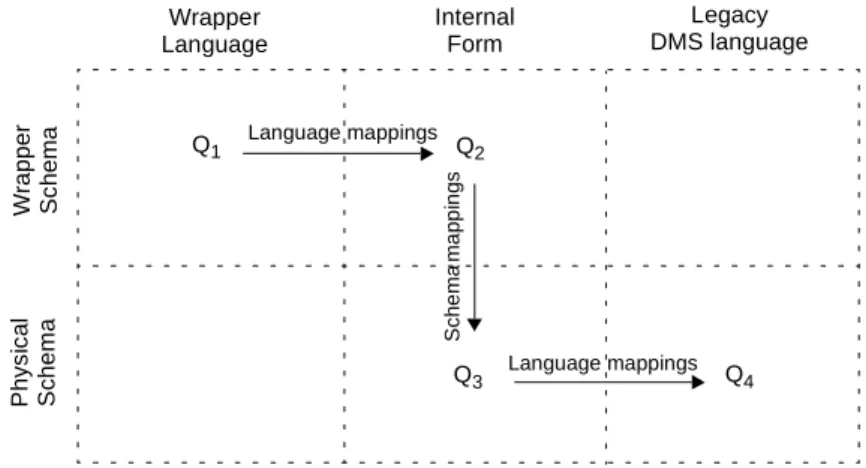
An analysis of the schema recovery and integration processes shows that deriving a schema from another one is performed through techniques such as renaming, translating, solving con-flicts, which basically are schema transformations. Most data-centered engineering processes can be formalized as a chain of schema transformations. This is the case for RDBE and inte-gration [Hainaut, 1999].
Both queries translation and results building rely in mappings and schemas description. The mappings are pure transformational functions that cannot be immediately translated into
ex-ecutable procedures in 3 GL. However, it is fairly easy to produce procedural data conversion programs [Thiran, 1999].
1.3
Scope and Overview
1.3.1 Scope
The InterDB project proposes a general architecture, a methodology and a CASE environment intended to address the problem of providing users and programmers with an abstract inte-grated view to independent, heterogeneous and distributed databases.
1.3.2 Overview
We distinguish three main tasks addressing the InterDB scope: (1) defining a generic integra-tion framework intended to express all the federaintegra-tion components, schemas and mappings; (2) building the wrappers for legacy source databases; and (3) defining a meta-mediator in-stantiated for federated schema.
Defining a generic integration framework
This issue is discussed in Part I of this report. It involves defining a unique and generic frame-work intended to express all the federation components, schemas and mappings.
In Chapter 2, we introduce the general architecture of database federations. We provide an overview of existing database federation architectures. We then introduce the main baselines of the InterDB architecture.
In Chapter 3, we present the generic data model intended to express the schema hierarchy of database federations. It is an abstract formalism from which the federation models can be de-rived by specialization. In short, physical schemas, conceptual schemas, export schemas as well as federated schemas are expressed into an unique and generic entity/object-relationship model. Besides the standard concepts, the meta-model includes some meta-objects which can be customized according to specific needs. These features provide dynamic extensibility of the generic model. For instance, new concepts such as correspondence types can be represent-ed by specializing the meta-objects.
In Chapter 4, we define the mappings as schema transformations. We present the concepts and properties of schema transformations. An inventory of useful transformations is present-ed. We finally introduce the notion of schema history.
Building wrappers for legacy databases
1.3 Scope and Overview 1-9 a CASE support for developing legacy data wrappers.
In Chapter 5, we present and develop the technology of legacy data wrappers. We discuss their main roles and services they provide. In particular, we show the close link between re-verse engineering and such wrappers. The architecture of an operational data wrapper - the InterDB wrapper - is then presented.
In Chapter 6, we present a generic and complete methodology for building legacy data wrap-pers. The methodology includes the schema recovery through a reverse engineering approach and the mapping building.
In Chapter 7, the methodology is supported by the DB-MAIN CASE tool that gives users an integrated toolset for reverse engineering and inter-schema mapping definition and process-ing. Wrapper generators for Cobol files and relational databases have been written as add-ons to DB-MAIN.
Defining the mediator
This issue is discussed in Part III of this report. We present an architecture, a methodology and a CASE support for developing mediators.
In Chapter 8, we present and develop the technology of data mediators. As for the wrappers, we start by discussing the main roles and services mediators provides. This chapter shows, among others, how queries against a federated schema can be processed in terms of queries against the underlying wrappers. Finally, the architecture of the InterDB mediator is present-ed.
In Chapter 9, we present an overview of the database integration methodology. The issues are raised and the approaches that have been proposed to tackle the problem are discussed. The InterDB approach is then presented and its main characteristics are outlined.
In Chapter 10, we present the DB-MAIN tools that are intended to support the mediator de-velopment. In particular, this chapter presents the extension of the DB-MAIN repository that describes both the schema hierarchy and the mappings between them.
Part I
Chapter 2
Integration Architecture
In which an overview of classical integration architecture of databases is given. The InterDB architecture is then presented and its main characteristics are outlined.
2.1
Introduction
Database systems that provide interoperation and varying degrees of integration among dis-tributed existing databases have been termed multidatabase systems ([Hurson, 1994], [Lit-win, 1986], [Lit[Lit-win, 1994]), federated databases ([Heimbigner, 1985], [Sheth, 1990]), and more generically, Heterogeneous Distributed Database Systems (HDDBS) [Bougettaya, 1998]. An attempt to relate some of the frequently used terms, using the fundamental dimen-sions of distribution, heterogeneity and autonomy has been presented in [Sheth, 1990]. The chapter is organized as follows. First, we present a taxonomy that classifies the existing solutions into three categories: global schema integration, federated databases and mutlidata-base language approach. Second, we describe the InterDB architecture
2.2
Overview of integration architectures
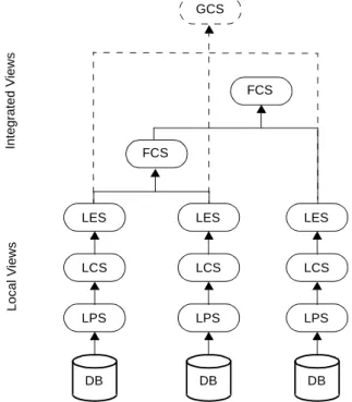
In [Sheth, 1990], a reference HDDBS architecture has been presented (Cfr. Figure 2-1). This architecture is based on mappings between schemas on 5 levels.
• Physical schema (LPS). A physical schema represents data in a data source. There is one physical schema for each data source. The physical schemas are expressed using a local data definition language and a local data model, if such exist.
• Component schema (LCS). A component schema is a CDM1 representation of a local schema. The local schema is translated into a CDM representation if the CDM is differ-ent than the local data model, otherwise the local and the compondiffer-ent schemas are the same.
• Export schema (LES). In some architectures, each data source decides the portion of the data that are going to be available for non-local access. The export schema models the view of the component schema visible non-locally. It is also expressed in the CDM. • Federated or Global schema (FCS or GCS). A federated (global) schema is an
integra-tion of all export schemas. Depending on the particular framework applied, this schema can be called either global or federated. The term global schema is used when there is only one such schema. There can be more than one federated schema.
• External schema. An external schema represents a subset of the global schema tailored for a particular user or group of users.
Figure 2-1: A Generic integration architecture. For simplicity, the export schemas have been
ig-nored.
1. Canonical Data Model.
LCS LES FCS In tegrat ed V iews Loc al V iews DB LPS LCS LES DB LPS FCS GCS LCS LES DB LPS
2.2 Overview of integration architectures 2-15 Depending on the level of integration, integration architectures can be classified into 3 cate-gories: global schema systems, multidatabase language systems and federated databases. These categories reflect design efforts to accommodate the conflicting requirements of achieving an efficient and usable systems by larger level of sharing on one side, and preserv-ing the autonomy of the data sources, on the other. On the one extreme of this spectrum are the systems that are closed to the distributed databases in building a global integrated schema of all the data in the sources. The opposite side represents systems that provide just basic in-teroperation capability and leave most of the integration problem to the user. The rest of this section overviews the features of each of these categories.
2.2.1 Global Schema Systems
A straightforward approach to building an HDDBS is the approach where the export schemas of multiple databases are integrated into a single view (global) schema [Spaccapietra, 1994]. In [Batini, 1986], a thorough survey on schema integration is provided and twelve methodol-ogies are compared.
The user is not aware of the distribution and the heterogeneity of the integrated data sources. Multiple databases logically appear as one single database to users. Furthermore, if the sche-ma does not change frequently, it can be stored locally, at the client, for faster access. Never-theless, this approach has been shown to exhibit the following problems [Bouguettaya,1998]: • Since the general problem of integrating even only two schema is undecidable, the pro-cess of integration of multiple schemas is very hard to automate. Global schema integra-tors must be familiar with all the naming and structure conventions of all the data sources and integrate them into a cohesive single schema without changing the local schemas. • There are two basic approaches to integrating the component schemas into a global
schema. In the first, the component schemas are integrated pair-wise. A hierarchical application of the integration leads to a schema integrating all component schemas. The other approach is to integrated all the component schemas at once. Both approaches have problems. The first one could produce different results when different integration orders are used, while the other one is usually too difficult.
The global schema integration is not suitable for frequent dynamic changes of schemas as the whole process of integration may need to be redone. As a result, it doesn't scale well with the size of the database networks.
2.2.2 Multidatabase Languages
This approach does not provide any type of global schema. The only means of accessing the data in the data sources is by language primitives for specification of queries over data stored in multiple sources. Information stored in different sources may be redundant, heterogeneous and inconsistent. These problems occur when component system are strongly autonomous.
The aim of a multidatabase language is to provide accesses involving several databases at the same time. Such language has features that are not supported in traditional languages. For in-stance, a global name can be used to identify a collection of databases. Queries can specify data from any local participating database (example: MSQL [Litwin, 1994]).
The main criticism of the multidatabase language approach is the low level of transparency provided to the user. The user is responsible for finding the relevant information, understand-ing each database schema, detectunderstand-ing and resolvunderstand-ing the semantic conflicts, and finally, build-ing the required view of the data in the sources. The advantages of the approach are that it is not intrusive against the autonomy of the data sources and there is no global/federated schema maintenance and access overhead.
2.2.3 Federated Architecture
In the federated MDBMS (FDBS), the export schema are only a subset of the component schemas. The federated schema does not need to be an integration of all the export schemas. It can be integrated only portions of the export schemas of interest to the users using the fed-erated schema. More than one fedfed-erated schema can be defined according to users require-ments. Each user can then further refine its export schema to fit his own requirerequire-ments. The aim of this architecture is to remove the need for static schema integration. It allows each local database to have more control over its sharable information. It should be noted that FDBS is a compromise between no integration and total integration. A typical FDBS archi-tecture would have a common data model and an internal command language.
The level of integration and services in a FDBS depends on how tightly/loosely coupled the component DMS are.
Tightly coupled systems
In a tightly coupled FDBS, federation administrators have full control on the creation and maintenance of federated schemas and access to export schemas. The aim is to provide loca-tion, replication and distribution transparency. This approach supports one or more federated schemas.
A federation repository keeps the mappings between the different schemas and helps main-tain uniformity in the semantic interpretation of multiple integrated components of data. The size of the repository can grow dramatically as the number of data sources and users in-crease. It can also become a performance bottleneck when accessed by a large number of us-ers. These problems are reminiscent of the problems of maintaining a global schema described above.
Once a federated schema is created, it is rarely changed; that is, it is static. This, it does not support dynamic changes of export/component schemas.
2.2 Overview of integration architectures 2-17
Loosely coupled systems
Loosely coupled systems do not have a centralized administrator. The user creates and main-tains his own integrated schema in the form of a local view. Creating a federated schema cor-responds to creating a view against the relevant export schemas. In that respect, each user must be knowledgeable about the information and structure of the relevant export schemas in order to create views. Federated schemas here are dynamic and, as a result, can be created and dropped on the fly. Multiple federation schemas are supported. The maintenance problems noted above disappears.
A possible drawback of this approach is that more than one user might need to perform the same view modeling, without the possibility of reusing the definitions. Furthermore, a change in an export schema affects all the users who have a view dependent on it.
A solution to the problems noted above is to allow a gradual transition from the federated into export schemas by a hierarchy of small intermediate schemas. This approach breaks the re-pository into smaller and more maintainable units, while allowing reuse of the view specifi-cation and modularity in the view definition and change.
Mediation architecture
To address the problem of interoperability of information systems in general, the term medi-ation has been defined in this context [Wiederhold, 1995] as a service that links data resources and application programs. The function of a mediator is to provide integrated information, without the need to integrate the data resources. A mediator hides details about the location and representation of relevant data to applications. Several prototype mediator systems have been developed ([Wiederhold, 1992], [Tomasic, 1996], [Garcia, 1997]).
Figure 2-2 shows the basic architecture of information processing using mediators. Compared to the client/server architecture, mediation introduces an additional layer in the architecture of information systems.
Figure 2-2: Wrappers/mediators architecture.
Wrapper DB LPS LCS LES Mediator FCS Wrapper DB
Mediation and databases
A database federation offers a virtual, integrated view of the underlying component databas-es. Queries issued against this view are translated into queries against the underlying compo-nent databases.
A legacy database federation performs mediation using at least two important components [Vermeer, 1997]: wrappers and mediators.
The function of a mediator is to provide integrated information, without the need to integrate the data resources. A mediator hides details about the location and representation of relevant data to applications.
Above each legacy database is a wrapper. A wrapper is a software component that performs the translation between the export schema and the physical schema of a source [Papakonstan-tinou, 1995]. That is, the wrapper (1) offers an export schema in the canonical data model (2) accepts queries against the export schema and translates them into queries understandable by the underlying database, and (3) transforms the results of the local queries into a format un-derstood by the application.
Wrappers and mediators relies on schemas descriptions and mappings to translate queries and to form the result instances.
2.3
InterDB Architecture
InterDB is a mediator/wrapper system for integrating pre-existing heterogeneous, distributed and legacy databases. It provides users with an unified federated schema and a single, high-level object-oriented interface to access data from any of the integrated local databases. Local databases remain fully autonomous.
2.3.1 Hierarchy Architecture
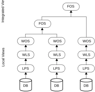
The InterDB hierarchy architecture is based on the five levels federated architecture [Sheth, 1990] with some simplifications (Figure 2-3). It comprises four schema levels:
• Local Physical Schema (LPS). It describes the physical data structure of the database as
they are implemented by the data manager. It holds structures and constraints explicitly declared in the DDL schema declaration or in data dictionaries.
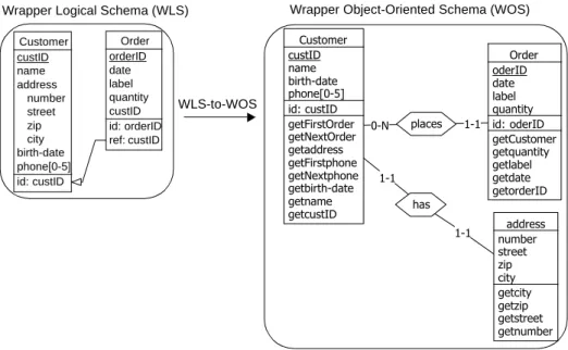
• Wrapper Logical Schema (WLS). It is the description of the data structures perceived by
users and programmers. In other words, it is the legacy database view offered by the wrapper. In the InterDB approach, the wrapper logical schema also includes implicit constraints, that is, data properties that have not been explicitly declared, but that are managed by, say, application programs.
2.3 InterDB Architecture 2-19 • Wrapper Object-oriented Schema (WOS). It is the object-oriented definition of a logical
schema. A wrapper logical schema is translated into an object-oriented schema through one-to-one mappings that convert entity types into object types and attributes into meth-ods.
• Federated Object-oriented Schema (FOS). It is an object-oriented federated view that
integrates the local objects of WOS. WOS and FOS are represented in the same
object-oriented formalism.
Figure 2-3: InterDB hierarchy architecture: local physical schemas, wrapper logical schemas,
wrap-per object schemas and federated object schemas.
2.3.2 Component Architecture
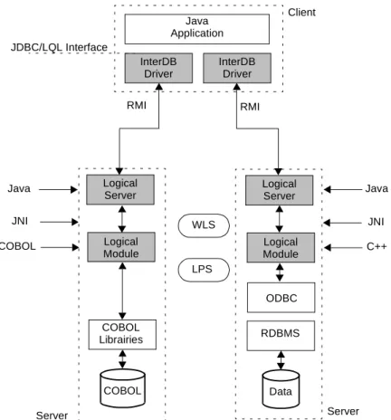
The InterDB architecture, shown in Figure 2-4, is close to standard proposals. It comprises a hierarchy of mediators, namely the legacy data wrapper dedicated to each database and a me-diator based on the federated object schema (FOS). These mediators offer remote Java objects
that hide the data distribution and the federation heterogeneity.
We have used the RMI system to manage the communications between the wrappers and the mediators.
Wrapper. A wrapper is in charge of managing the physical/object conversion of each local database. It comprises two components, namely the logical wrapper and the object wrapper. The logical wrapper hides the syntactic idiosyncrasies and the technical details of the DMS
WLS WOS FOS In te grat ed V iews Loc al V iews DB LPS WLS WOS DB LPS FOS WLS WOS DB LPS
of a given model family. In addition, it makes the implicit constructs and constraints explic-itly available. For instance, relational databases and flat COBOL files appear as similar log-ical structures. A loglog-ical wrapper dynamlog-ically transforms queries (top-down) and data (bottom-up) from this logical model to the actual physical model. In particular, it emulates implicit constructs such as foreign keys in COBOL files or multivalued fields in relational DB. The object wrapper provides a remote object-oriented view of a local logical database. It appears as a remote object server that offers a unique abstract interface to Java programs. For performance reason, we have decided to develop the wrappers as program components dedicated to a local database. In particular, the logical/physical and object/logical mapping rules are hardcoded in the modules rather than interpreted from mapping tables.
Figure 2-4: The InterDB component architecture of a federated database. To simplify the figure,
ex-port and view schemas have been ignored.
Mediator. The mediator offers an object-oriented interface based on the FOS. It provides
global remote objects that hide data distribution across the different sites. For flexibility rea-son, the mediator is based on the DB-MAIN repository that describes the federated object-oriented schema, the local object-object-oriented schema of each wrapper, its location, and the rela-tionships between local and global schemas. Information concerning data replication, seman-tic conflicts and data heterogeneity allows the server to interpret and distribute the global objects, and to collect and integrate the results sent back by the local wrappers.
The architecture model depicted in Figure 2-4 provides an adequate framework for solving the heterogeneity issues discussed in Chapter 1. DMS and local semantic independence is guaranteed by the local wrappers. Location and global semantic independence is provided by the mediator. This module provides data global access irrespective of their location and re-solves semantic conflicts. Finally, platform independence is ensured by both the local wrap-pers, Java and RMI as a middleware.
Wrapper DB LPS Mediator FOS Wrapper DB Repos Logical Wrapper Object Wrapper WLS WOS
Chapter 3
Generic Data Model
In which the generic data model of the federation is presented. The generic model is able to describe data structures at different levels of abstraction, ranging from physical to conceptual, and according to various modeling paradigms.
3.1
Introduction
Over the year, several data modelings have been used as legacy data models: hierarchical, network, relational, semantic and object-oriented models. Schemas that correspond to these legacy data models are translated into schemas using a Canonical Data Model (CDM). This allows for resolving syntactic heterogeneity that is the result of different data models. For ex-ample, in the Multibase system, the legacy DMS are relational and network systems, and the CDM follows the functional model.
It is usually expected that the modeling power of the CDM is richer than the legacy data mod-els. The relational model has frequently been used as the CDM with relational, hierarchical and network databases. Since the entity-relationship model has been the overwhelming tool for conceptual modeling, early efforts in data modeling translation research focused on the transformation to and from the ER model. Next, there has been a shift to using the object-oriented model as the focal model through which other models have to be translated to or from ([Urban, 1991], [Vermeer, 1996], [Roantree, 2001]). The shift has been spurred on by the fact that the object-oriented model can be used as a tool for both design and implementa-tion. The current tendency is to use XML as the CDM ([Manolescu, 2001], [Gardarin, 2002]). This is advocated for interoperable systems because of the ease of representing both struc-tured and semi-strucstruc-tured data. Another reason for choosing XML as a standard for
informa-tion interchange is its flexibility, portability and simplicity [Manolescu, 2001]. An interesting discussion on the different models used as CDM can be found in [Elmagarmid, 1999]. In the InterDB approach, we define a high-level generic data model, namely the generic data model, such that it is possible to represent the constructs whatever their underlying data model and their abstraction level. As we will see in the next sections, the generic data model can be used as a unifying model for any legacy and canonical data models.
3.2
Generic Data Model
The generic data model is an abstract formalism intended to express data structures indepen-dently of the implementation technologies. For methodological reason, we propose a unique generic model from which several abstract submodels can derived by specialization. In short, physical schemas, wrapper logical schemas as well as object-oriented schemas are expressed into an unique and generic entity/object-relationship model (Figure 3-1).
Figure 3-1: The data model hierarchy.
Besides the standard concepts, the generic data model includes some meta-objects which can be customized according to specific needs. These features provide dynamic extensibility of the generic model. For instance, new concepts such as correspondence types can be represent-ed by specializing the meta-objects.
3.2.1 Main concepts
The main concepts of the generic model are illustrated graphically in Figure 3-2. Figure 3-3 summarizes the six major constructs of the generic data model. The central construct is that of entity type, or object type (Customer), that represents any homogeneous class of
concep-tual, component or physical entities, according to the abstraction level at which these entities are perceived. Entity types can have attributes (CustCode, Price, UnitPrice), which can be
LPS WOS FOS OO Data Model Wrapper Logical Model Legacy Data Model WLS Generic Model Canonical Data Models
3.2 Generic Data Model 3-23 atomic (QtyOH) or compound (Price), single-valued (Name) or multivalued (Price),
manda-tory (Name) or optional (Phone). Cardinality [i-j] of an attribute specifies how many values
(from i to j) of this attribute must be associated with each parent instance (entity or compound value). The values of some attributes, called reference attributes (DETAIL.ItemCode), can be
used to denote other entities (i.e., they form some kind of foreign keys). Relationship types (places, has) can be drawn between entity types. Each of their roles (places.ORDER) is
char-acterized by a cardinality constraint [i-j], stating that each entity must appear in i to j relation-ships. Additional constraints such as identifiers made of attributes and/or roles as well as existence constraints (coexistence, exclusive, at-least-one, etc.) can be defined. Constructs such as access keys (ITEM.{Name}), which are abstractions of such structures as indexes and
access paths, and storage spaces (File_DOC) which are abstractions of files and any other
kinds of record repositories, are components of the generic model as well. A processing unit (CUSTOMER.Remove) is the abstraction of a program, a procedure or a method, and can be
attached to an entity type, a relationship type or a schema.
Figure 3-2: An illustration of the generic model. This schema includes entity types, relationship
types, attributes, identifiers and processing units. It also includes foreign keys, access keys and storage spaces. This hybrid schema includes constructs from different levels of abstraction.
1-1 0-N has 1-1 0-N places ORDER OrdNum OrdDate id: OrdNum Record() Archive CreateInvoice ComputeAmount ITEM ItemCode Name QtyOH Price[0-5] MinOrdQty UnitPrice id: ItemCode acc acc: Name Is_Available()? ComputeUnitPrice() DETAIL SeqNum Qty ItemCode id: has.ORDER SeqNum ref: ItemCode Record() Remove ChangeItem() CUSTOMER CustCode Name Address Phone[0-1] id: CustCode Register() Remove CheckPayment File_DOC DETAIL ORDER CUSTOMER
Figure 3-3: The six main concepts of the generic data model.
3.2.2 Meta concepts
Besides the main concepts, the generic data model includes some meta objects which can be customized according to specific needs.
• Meta-property: user-defined property of a construct, in addition to built-in properties such as name, type, length, semantic, etc.
• Stereotype: a specific category of a construct; an instance of a construct can belong to zero, one or several stereotypes; a stereotype can be given specific properties and spe-cific behaviour.
These features provide dynamic extensibility of the generic model. For instance, new con-cepts such as organizational units, servers, or geographic sites can be represented by meta-properties. Following [Busse, 1997], we can distinguish the following kinds of meta-proper-ties:
• Mapping meta-property describes the correspondence between constructs of two differ-ent schemas.
• Technical meta-property describes information regarding the technical access mecha-nisms of components, such as the protocol, speed of connection, cost of queries, query capabilities and so on. It is used to bridge technical and interface heterogeneity.
• Semantic meta-property is information that helps to describe the semantic of concepts. In particular, ontologies and thesauri are used for this purpose. All domain-specific descrip-tions belong to this class.
• Quality-related meta-property describes source-specific properties of information sys-tems regarding their quality, such as reliability, update frequency, actuality, comprehen-siveness, etc. This is used for ranking or optimization.
Entity/object type Category of similar data/information units
Attribute Common property of the entities of a given type; atomic/ compound, single-valued/multivalued, optional/manda-tory, value/entity-based
Relationship type Type of aggregate comprising roles and attributes Group List of attributes/roles attached to a parent (entity type,
rel-type, compound attribute); can be given functions: identifier, existence constraint, access key, etc.
Inter-group rela-tionship
dependency between groups; example: foreign key, functional dependency, inclusion constraint
3.2 Generic Data Model 3-25 • User-related meta-property describes responsibilities and preferences of users of the
information systems, e.g. user profiles.
3.2.3 Model specialization
This generic model can be specialized into the legacy data model, the wrapper data model and the canonical data model. These models are built by selecting generic constructs and struc-tural constraints, and by renaming constructs to make them comply with the concept taxono-my of the specialized model. Figure 3-4 shows some common interpretation of the generic constructs. For example, the relational model, considered as a legacy data model, can be pre-cisely defined as follows (IMS, Cobol or OO models can be defined in the same way): • Selecting constructs. We select the following constructs: entity types, attributes,
identifi-ers and reference attributes.
• Structural constraints. An entity type has at least one attribute. The valid attribute cardi-nalities are [0-1] and [1-1]. An attribute must be atomic.
• Renaming constructs. An entity type is called a table, an attribute is called a column, an identifier, a key and a group of reference attributes, a foreign key.
In the same way, an object-oriented data model (e.g., a variant of the UML class model) can be described as follows:
• Selecting constructs. We select the following constructs: entity types, IS-A relations, processing units, attributes, relationship types, identifiers.
• Structural constraints. An entity type has at least one attribute. A relationship type has 2 roles. An attribute is atomic. The valid attribute cardinalities are [0-1] and [1-1]. An identifier is made up of attributes, or of one role + one or more attributes. Processing units are attached to entity types only.
• Renaming constructs. An entity type is called a class, a relationship type is called an association, a processing unit is called an operation, an attribute is an attribute, the cardi-nality of the opposite role is called multiplicity and an identifier comprising a role is called a qualified association.
Figure 3-4: Some common interpretations of the generic concepts.
3.3
Federation Data Models
The federation data models include the legacy data models supported by the legacy databases and the canonical data models. In this section, we present these models and illustrate them by a small common example. These models are interpreted as specializations of the generic mod-el described above.
3.3.1 Legacy Data Models
Over the years, several data modelings have been used to design universes of discourse: re-lational model, network model (CODASYL DBTG), hierarchical model (IMS), shallow model (TOTAL, IMAGE), inverted file model (DATACOM/DB), standard file model (CO-BOL, C, RPG, BASIC) or object-oriented model.
Due to the large variety of model families, it is not easy to propose an exhaustive description of their own constructs and constraints. As far as the InterDB project is concerned, we will consider two popular legacy data models only: the COBOL model and the relational model.
COBOL data model
The COBOL data model imposes few constraints on attribute structures (Figure 3-5). The most important one concerns multivalued attributes, which can be represented through list at-tributes only. In addition, optional atat-tributes are not explicitly represented except as multiva-lued attributes.
An example of a COBOL schema is shown in Figure 3-6. In this model, record types have
Generic ER Relational COBOL
Entity/object type
Entity type Table Record type
Attribute Attribute Column Field
Relationship type Relationship type Group Identifier Constraint Primary key Foreign key Index Record key
3.3 Federation Data Models 3-27 only one record key (e.g. Customer has one attribute that plays the role of identifier and
ac-cess key). Attributes are atomic or compound (e.g. address) or multivalued (e.g. phone). All
the attributes are mandatory. Names are formed according to the COBOL language syntax.
Figure 3-5: Concepts and constraints of the COBOL data model.
Figure 3-6: COBOL structure example.
Relational data model
The attribute structure in the relational data model is particularly poor (Figure 3-7): an at-tribute must be single-valued and atomic. It can nevertheless be optional. Moreover, the rela-tion data model introduces the concept of foreign key that is not defined in the COBOL data
Generic Model COBOL Model Constraint
Entity/object type Record Type
Attribute Field Mandatory
Single-value atomic attribute Single-value elementary field Mandatory
Compound attribute Compound field Mandatory
Multivalued attribute ... occurs N times Mandatory
Identifier + access key Record key, alternate record key
Only one attribute Non-identifier access key Alternate record key with
du-plicates
Only one attribute
Collection Files Order orderID date label quantity ORD-custID id: orderID acc Customer custID name address number street zip city birth-date phone[5-5] array id: custID acc F-Customer Customer F-Order Order
model.
Figure 3-7: Concepts and constraints of the relational data model.
An example of a relational data schema is shown in Figure 3-7. In this model, tables have pri-mary and unique keys (e.g. Customer has two identifiers: primary and secondary). All the
at-tributes are atomic and single-valued. Atat-tributes can be mandatory or optional (e.g. phone).
Tables can have one or several foreign keys (e.g. custID is a referential attribute of Order. It
references custID attribute of Customer). Names are formed according to the relational
lan-guage syntax.
Figure 3-8: Relational schema example.
3.3.2 Canonical Data Models
A canonical data model is designed to express all the semantics of the local schemas [Sheth, 1990]. As a result, it is usually expected that its modeling power is richer than the data models
Generic Model Relational Model Constraint
Entity/object type Table
Attribute Column Single-valued, atomic
Optional attribute nullable column Single-valued, atomic
Primary identifier Primary key Must be an index
Secondary identifier unique (column/table predi-cate)
unique index
Must be an index
Referential key Foreign key
Access key Index
Collection Tablespace, DBspace, etc.
Order orderID date label quantity custID id: orderID acc ref: custID acc Customer custID name address birth_date phones[0-1] id: custID acc
3.3 Federation Data Models 3-29 followed by the legacy databases. A canonical data model must therefore include at least all the structures and constraints of any underlying legacy data schemas based on the legacy data models.
In InterDB, we propose two canonical data models: the wrapper logical model associated with a common data manipulation language close to SQL and the object-oriented model that offers object methods for accessing read-only data.
Wrapper logical model
The Wrapper Logical Model (WLM) hides the syntactic idiosyncrasies and the technical
de-tails of the DMS of a given model family. Since we only consider the COBOL and relational data models as legacy data models, we defined WLM as a model that includes all the structures
and constraints that exist explicitly in these two data models (Figure 3-9). As a result, WLM
comprises entity types and attributes (that can be mono- or multi-valuated; atomic or com-pound, mandatory or optional) as constructs; identifiers and referential attributes as con-straints.
An example of a schema of this model is shown in Figure 3-10. In this model, entity types may have one or two identifiers constituted of one or more attributes or roles (e.g. Customer
has one identifier constituted of one attribute). Attributes are atomic or compound (e.g. ad-dress). Attributes may be mandatory (e.g. name attribute of Client) or optional (e.g. birth-date
attribute of Customer). Attributes may also have several values (e.g. phone attribute of Cus-tomer). Entity types may have one or several referential attributes (e.g. custID is a referential
attribute of Order. It references custID attribute of Customer). Names are formed according
to host language syntax.
Figure 3-9: The wrapper logical model: constructs and constraints.
Constructs Constraints
ET Attributes: any number
Identifier: any number
Attribute Atomic / compound
card: [1-1],[0-1], [0-i] Attribute Domain Char(n), Num(n), Num(n,m)
Identifier n level-1 attributes
Referential attributes n level-1 attributes
Figure 3-10: Wrapper logical schema example.
3.3.3 Object-oriented Model
The object-oriented model (Figure 3-11) provides rich data structuring possibilities, which enables them to express all the semantics of the wrapper logical schemas. Moreover, it mits the specification of behaviours (through the processing units), which can be used to per-form complex mappings among the schemas of a database federation. Thus, we can use this model for modeling both the local and global schemas.
An object type (named entity type in the generic model) definition is structured in three tions: the structure section, in which for instance, attributes can be defined, a constraint sec-tion in which constraint groups are defined, and a method secsec-tion in which operasec-tions on objects are defined.
Figure 3-11: The object-oriented data model: constructs and constraints.
Constructs Constraints
ET Attributes: any number
Identifier: any number
Attribute Atomic / compound
card: [1-1],[0-1], [0-i] Attribute Domain Char(n), Num(n), Num(n,m)
Identifier n level-1 attributes
Relationship type one-to-one, one-to-many Processing unit (method)
Names Host language compliant
Order orderID date label quantity custID id: orderID ref: custID Customer custID name address number street zip city birth-date phone[0-5] id: custID