HAL Id: hal-02480070
https://hal.archives-ouvertes.fr/hal-02480070
Submitted on 14 Feb 2020
HAL is a multi-disciplinary open access
archive for the deposit and dissemination of
sci-entific research documents, whether they are
pub-lished or not. The documents may come from
teaching and research institutions in France or
abroad, or from public or private research centers.
L’archive ouverte pluridisciplinaire HAL, est
destinée au dépôt et à la diffusion de documents
scientifiques de niveau recherche, publiés ou non,
émanant des établissements d’enseignement et de
recherche français ou étrangers, des laboratoires
publics ou privés.
The behavior of a building using RES energy and A
control strategy of DC microgrid
Mouna Abarkan, Byou Abdelilah, Nacer K M’Sirdi, El Hossain Abarkan
To cite this version:
Mouna Abarkan, Byou Abdelilah, Nacer K M’Sirdi, El Hossain Abarkan. The behavior of a
build-ing usbuild-ing RES energy and A control strategy of DC microgrid. 2019 International Conference of
Computer Science and Renewable Energies (ICCSRE), Jul 2019, Agadir, Morocco.
�10.1109/ICC-SRE.2019.8807673�. �hal-02480070�
The behavior of a building using RES energy and
A control strategy of DC microgrid
Mouna ABARKAN
Laboratory Signals, Systems and Components (LSSC) Faculty of Science and Technical of
Fez, USMBA, P.O. Box:2202
Fez Morocco [email protected]
Byou Abdelilah
Laboratory Signals, Systems and Components (LSSC) Faculty of Science and Technical of
Fez, USMBA, P.O. Box:2202
Fez Morocco [email protected]
El Hossain Abarkan
Laboratory Signals, Systems and Components (LSSC) Faculty of Science and Technical of
Fez, USMBA, P.O. Box:2202
Fez Morocco [email protected]
N.K.M’Sirdi
Laboratory of Sciences Information and Systemes (LSIS), Polytechnique ,AMU Aix Marseille
University, IC STAR
Marseille, France [email protected]
Abstract— The building is the largest consumer of energy, before the transport and industry. It also accounts for 25% of emissions of carbon dioxide on the national level, it consumes a lot of energy for the production of domestic hot water (DHW) and the heat and cold production. For this reason, the building is considered a huge reservoir of potential energy savings, hence the existence of numerous research studies on this topic, [1]. So to reduce this consumption we thought to integrate renewable sources of energy (RES) using a control strategy of DC building. The objective of this paper is to present a model of a building equipped with RES, different electrical loads, and behavior of the energy consumption of a building in real time using multi-physics description software package known as Simscape and we propose also a 230V DC microgrid which consists of a 20 KWp photovoltaic panel, batteries and DC loads and also a hierarchical control strategy to ensure balance power of the DC microgrid and the maintenance of common DC bus voltage is presented.
Keywords—Building, PV, Batteries, DC microgrid, hiearchicl control and a droop control method.
I. INTRODUCTION
Currently, many countries have been promoting low-energy buildings and zero energy buildings each building have promoted the development of DC loads such as differents loads for exemple LEDs lighting, washing machine, TV,refrigerators,electric vehicul, etc…, and renewable energy sources (PV,Batteries…). Corresponding with this change, many studies have indicated that DC microgrids are more suitable for the distribution system in buildings than AC distributed grids. The main advantages of DC microgrids are high energy efficiency and much easier integration with distributed energy sources and storage systems.
The objective of this paper is to develop a reliable model of a building composed by four apartments and each apartment is composed by four rooms (two rooms with isolation which are the bedroom, living room and two room without
isolation which are the kitchen and bathroom) which are the bedrooms and living room that have under floor heating and radiators to heat through, a bathroom that includes a heater to heat the towels and a kitchen which includes a heated floor. It also includes the various electrical loads such as washing machine, freezer, refrigerator and some electrical power demands. In order to develop optimized solutions for multiple sources used in urban areas, we develop a real-time simulation model of an example of a realistic system and we present also a hierarchical control strategy for the reliable and economical operation of a grid-connected DC microgrid supplying an office building.
In the first section we will present our building and then go to the second section from which we will show the models of the plant subsystems. The house considered here is equipped by four rooms and each room is equipped by four walls, a ceiling, doors and a windows with double glazing and each room is connected to an under floor heating and a complementary electric heater to control the house temperature. The objective of this section is to be able to simulate the thermal model of the house using Simscape to get close to reality, [6].
In the third section we present the model of the renewable energies transformation (PV, Batteries...) and simulation of the dynamics and time variations of the sources.
In the fourth section we describes the configuration and control strategy of DC microgrid in various typical conditions and the simulation results are displayed in Section five and finally a conclusion that summarizes our works.
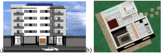
The Figure 1 shows the model of the building or our Apartment, in a) the building with different RES, and in b) the house with four rooms.
2
a) b)
Fig. 1. Model of the building a) the building with different RES, b) The house with four rooms.
II. MODEL OF THE BUILDING
There are a large number of modeling methods whether physical and numerical models. In this paper, we chose the physical model to approach a reality, to get one will present in this section the model of our building is composed by 4 apartment and each apartment consists four rooms and each room is connected to an under floor heating and a complementary electric heater to control the house temperature using Simscape.
A. Simulation model of building component
The objective of this section is to be able to simulate the thermal model of the apartment using Simscape. The different models of the components of this as the walls, windows, ceiling, floor, etc., will be developed and simulated using Simscape. The hypotheses considered are the following [3,4,5]:
-The temperature of a ceiling or a floor is uniform, -The temperature measurement is instant (no delay), low noise,
For the simulation of the whole model in Simscape we use: -Two sensors for measuring the temperature and the heat flux,
-A temperature source and a source heat flow,
-A conduction exchange unit, which represents the transfer by conduction between two layers of the same material, -An exchange unit by convection, which transfers heat between two bodies
-A thermal mass block representing the thermal inertia. This studied is divided into different sub-components for each room we consider: the four walls, the windows, the door, the heater, and the ceiling (the floor is simulated coupled with the heating subsystem).
The model of the wall
The model of a wall with isolation is illustrated in figure 2 . It consists of three layers: an outer parpain wall, an isolation layer and an inner wall (often in brick or drywall),
Fig. 2. The wall model with isolation
The model of the window with double glazing
The figure 3 shows the model of the window with a double glazed [3].
Fig. 3. The windows model with isolation.
B. The Models of the thermal heating Systems
The models of the thermal heating systems is compound of the under floor heating, electric radiator, the heat pump (HP) and the storage model.The aim goal of this subsection is to present the model of the thermal heating for our model using an under floor heating system, heat storage and electric radiator [3,4,5,6,7].
Model of the under floor heating
The model of an under floor heating system is presented in figure 4, we used the same blocks mentioned earlier by adding two sources that are the sources of temperature and of heat flow.
Fig. 4. Model of the under floor heating.
Heat Storage Model
The model used here is a storage tank that stores the solar thermal energy. It is defined as follows see [4,5]:
The Electric radiator Model
The model of heater is presented as follows (in Figure 5) where Theater= 50 °C:
Fig. 5. Model of the under floor heating.
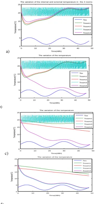
The figure 6 shows the variation of the external and internal temperature in different state in the 4 rooms for two days [3].
a) Shows the result of temperature when the under floor heating is active in the bedroom, living room and the kitchen, the electrical heater is activate in the bathroom.
b) Shows the result of temperature, when we active the under floor heating in the bedroom and in the living room, in the kitchen(without isolation) we not activate the under floor heating , the electrical heater is activate in the bathroom.
c) Shows the result of temperature, when we active the under floor heating in bedroom, in the kitchen(without isolation) and in the living room(with isolation) we not activate the under floor heating , the electrical heater is activate in the bathroom.
d) Shows the result of temperature, when we not active the heater in all in the house.
a) 0 10 20 30 40 50 0 5 10 15 20 25 Time(48h) Te m pe ra tu re (° C )
The variation of the internal and external temperature in the 4 rooms
Tex Troom1 Troom2 Troom3 Troom4 0 10 20 30 40 50 0 5 10 15 20 25 Time(48h) Te m pe ra tu re (° C )
The variation of the temperature
Tex Troom1 Troom2 Troom3 Troom4 b) c) 0 10 20 30 40 50 0 5 10 15 20 25
The variation of the temperature
Time(48h) Te m pe ra tu re (°C ) Tex Troom1 Troom2 Troom3 Troom4 0 10 20 30 40 50 0 5 10 15 20 25 Time(48h) Te mp era tur e(° C)
The variation of the temperature Tex Troom1 Troom2 Troom3 Troom4 d)
Fig. 6. The variation of the external and internal temperature in different state in the 4 rooms for two days
III. THE RESMODELS
A. Model of the PV
The combination of several PV cells in series and / or parallel result in a photovoltaic generator that has a characteristic non-linear current-voltage having, according to its polarization, a maximum power point of output.
The simulated system consisting of a PV panel, boost type converter, a battery and a control system. The control system ensures the regulation and management of energy as well as the search for maximum power point. The battery is integrated into the PV array. It allows the storage of solar electricity for single systems and serves as a power conditioner.The MPPT control varies the duty cycle of the converter such that the power supplied by the generator is the Pmax provided at its terminals. However, the MPPT control is generally based on the variation of the duty cycle (D) of the converter, for have a PPM (the maximum power point) we have chosen a duty cycle equal to 0.5% ,as we shows the figure 7 and the figure 8 present the simulation of duty cycle [6,10].
Fig. 7. Model of the PV in the Matlab/Simulink
Fig. 8. The simulation result of a duty cycle of the PV
B. Model of the battery
The energy storage on batteries is necessary despite that we consider immediate use of the produced power. PV sources do not produce electricity during night and power production during the day may exceed the demand.
We can then place the exceeding quantity of energy on batteries to allow further use. The operation of the energy storage is always associated with the reverse operation of recovering the energy stored. The figure 9 shows a generic and dynamic simple model of a battery used to represent the most commonly used batteries. The internal resistance is assumed to be constant during charging cycles and discharge, and does not vary with the magnitude of the current. Parameters of the model are derived and discharge characteristics are assumed to be the same for the load. Note that more complex models can also be used, this one has been chosen in a first step for simplicity [8,9,10].
4
Fig. 9. Matlab Battery simple model
The table 1 present the parameters of pv panels with their value and unit and the table 2 present the parameters of a battery with its value and unit.
TABLE I. PARAMETERSOFPVPANELS
Parameter Value Unit
Number of cells of one panel 96 - Number of parallel panels 16 -
Number of series panels 4 -
Rated power 20 KW
Fig. 10. Parameters of PV panels
TABLE II. PARAMETERSOFABATTERY
Parameter Value Unit
Number of series batteries in a
bank 20 -
Number of parallel banks 2 -
Nominal voltage 240 V
Nominal discharge current 56.52 A
Rated capacity 130 Ah
Fig. 11. Parameters of a Battery
IV. SYSTEM CONFIGURATION AND COTROL STRATEGY
A. Configuration of DC Microgrid:
The principale of a direct current building is based on the fact that most electrical appliances in buildings are direct current, such as computers, televisions, telephones, light-emitting diodes (LEDs) and efficient direct current motors require a direct current source. In addition to internal electrical appliances, the number of electric vehicles (EVs) is growing rapidly. In addition, energy sources (e.g. PV panels) and building storage systems are based on DC technology. This proves that the DC building seems to be a good solution.
It is supposed that the design of a DC microgrid for a building is configured as in Figure 12. This
DC microgrid
is composed by a photovoltaic panels on the roof of the building, battery bank and DC loads. The PV panels work in MPPT mode to extract the maximum power. The objective of the proposed control strategy is to ensure load sharing power and maintaining system stability.
Fig. 12. Layout of a DC microgrid supplied by a PV-battery.
B. Control strategy
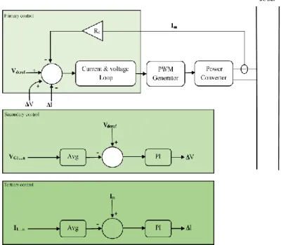
To avoid the conflict between voltage regulation and load distribution, a mixed compensation method has been proposed in the literature can be found in [11] and illustrated in Figure 13. The DC bus voltage can be restored by the global voltage compensation generated by common voltage or current information, while load balancing requires common current information. This type of compensation uses the shared voltage information to generate a global voltage compensation.
Fig. 13. The control procedure for the proposed method.
V. SIMULATION RESULTS
the simulation is performed in the Matlab/Simulink environment to validate the proposed control strategy, under the following conditions: The nominal voltage of the DC bus Vdcn was set to 230 V. A variable load curve of the apartment. A model of a PV panel was built in the Matlab/Simulink environment. The nominal power of the PV was 20 kW peak.
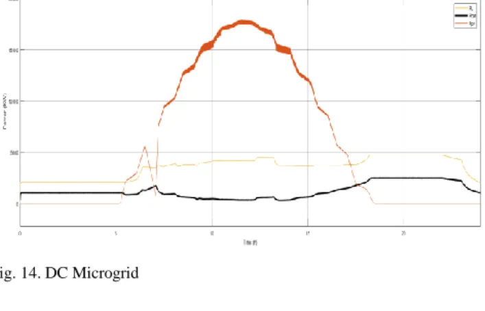
The figures 14 and 15 shows the simulation results of the DC microgrid and the voltage changes of the DC bus and other sources of energy for 1 day( 24 hours).
Fig. 14. DC Microgrid
Fig. 15. DC Bus voltage
From 0 am to 6 am, the PV power is zero, the batteries are charged to supply the charges of the apartment and the DC bus voltage is stable. from 8h the PV power increases so the charges will be supplied by the PV source and the batteries are charged to absorb the remaining power. In the evening, there is no PV power. As a result, the bus voltage decreases and the batteries go into discharging mode to power the load. The battery discharge power from 0h to 8h in the morning is lower than between 17h and midnight due to the varying consumption of the apartment. These simulation results validate the control strategy presented in this paper.
I. CONCLUSION
In this paper, we presented a study to model and simulate the energy behaviour of a building using Simscape. The system includes a building, a photovoltaic generator and a battery storage system to adapt energy production from renewable sources according to the required load and we also present a hierarchical control strategy to ensure power sharing between the different elements of the DC microgrid and maintenance of DC bus voltage. Finally, the feasibility and performance of the control strategy presented for the effective operation of the stand-alone DC system was tested in the Matlab/Simulink environment.
REFERENCES [1] http ://www2.ademe.fr.
[2] Mouna Abarkan, Nacer K.M'Sirdi, F. Errahimi. ―Analysis and Simulation of the Energy Behavior of a Building equipped with RES in simscape‖ Elseiver, journal Energy Procedia en Science Direct. Energy Procedia 2014, Volume 62, 2014, Pages 522-531.
[3] Mouna Abarkan , Fatima Errahimi , N. K. M'Sirdi " Modélisation et Simulation d’un Système hybride pour l’exploitation des énergies renouvelables dans un bâtiment " Workshop WOISA'13,Mai Taza.
[4] Mouna Abarkan, Nacer K.M'Sirdi, Fatima Errahimi. Modélisation et Simulation d'un Système de production d'énergie renouvelable Multi-sources et Multi-utilisateurs. Revue Méditerranéenne des Télécommunications (RTM), 2014, Volume 4, 2014, Pages 9-13.
[5] User’s Guide Matlab Simulink, 2007-2010 by the MathWorks.
[6] A.W.M. (Jos) van Schijndel and M.H. (Martin) de Wit, Advanced simulation of building system and control with Simulink, 8th International IBPSA Conference Eindhoven, Netherlands, August 11- 14, 2003.
[7] Mouna Abarkan, Fatima ERRAHIMI, NacerK.M’Sirdi, Aziz NAAMANE " Analysis of Energy Consumption for a Bulding using wind and solar Energy Sources. " Elseiver, journal Energy Procedia en Science Direct. Energy Procedia 2013, Volume 42, 2013, Pages 567-576.
[8] Tremblay, O.; Dessaint, L.-A.; Dekkiche, A.-I., A Generic Battery Model for the Dynamic Simulation of Hybrid Electric Vehicles, Vehicle Power and Propulsion Conference, 2007. VPPC 2007. IEEE 9-12 Sept. 2007, pp. 284-289
[9] C. M. Shepherd, Design of Primary and Secondary Cells - Part 2. An equation describing battery discharge, Journal of Electrochemical Society, Volume 112, Jul. 1965, pp. 657-664 [10] Huang, P.H.; Xiao, W.; El Moursi, M.S. A practical load
sharing control strategy for DC microgrids and DC supplied houses. In Proceedings of the IECON 2013—39th Annual Conference of the IEEE Industrial Electronics Society, Vienna, Austria, 10–13 November 2013; pp. 7124–7128. [11] Ma, T.T.H.; Yahoui, H.; Vu, H.G.; Siauve, N.; Morel, H. A
Control Strategy of DC Building Microgrid Connected to the Neighborhood and AC Power Network. Buildings 2017, 7, 42.