Design and Feedback Control of Self-folding
Untethered Miniature Origami Robots
by
Steven Paul Guitron
S.B., Massachusetts Institute of Technology (2015) Submitted to the Department of Mechanical Engineering in partial fulfillment of the requirements for the degree of
Master of Science in Mechanical Engineering at the
MASSACHUSETTS INSTITUTE OF TECHNOLOGY June 2017
@
Massachusetts Institute of Technology 2017. All rights reserved.A uthor ... ... . . . . . . . . . . . . . . . . . . . . . . . . . . . . . irt nt of Mechanical Engineering
AT 12 2)017 C ertified by ... ... ... ... Daniela Rus Professor Thesis Supervisor Certified by... Accepted by ... MASSASTTS INSTITUTE OF TECHNOLOGY
JUN 2 1 2017
LIBRARIES
Sangbae Kim Professor sis Sup. .. . .. . . ... . . . .. . . .. . . .. . .. . . . .. . . .. . . . .
...
Rohan Abeyaratne Chairman, Committee on Graduate Students Graduate Officer... ... n.
Design and Feedback Control of Self-folding
Untethered Miniature Origami Robots
by
Steven Paul Guitron
S.B., Massachusetts Institute of Technology (2015) Submitted to the Department of Mechanical Engineering in partial fulfillment of the requirements for the degree of
Master of Science in Mechanical Engineering at the
MASSACHUSETTS INSTITUTE OF TECHNOLOGY June 2017
@
Massachusetts Institute of Technology 2017. All rights reserved.Author...
Certified by ...
Certified by...
Signature redacted
Depart nt of Mechanical Engineering
3ignature
redacted
Signature redacted
May 12, 2017 Daniela Rus Professor Thesis Supervisor Sangbae Kim Professor Accepted by...MASSA RTUR1ETS INSTITUTE OF TECHNOLOGY
JUN 2 12017
LIBRARIES
r-% A 'Jesis Supervhir,...
Signature redacted
Rohan Abeyaratne Chairman, Committee on Graduate Students Graduate OfficerDesign and Feedback Control of Self-folding Untethered Miniature Origami Robots
by
Steven Paul Guitron
Submitted to the Department of Mechanical Engineering on May 12, 2017, in partial fulfillment of the
requirements for the degree of
Master of Science in Mechanical Engineering
Abstract
Small robots that can be manufactured rapidly and inexpensively have numerous scientific applications. Current manufacturing processes for robots are made specific to the robot, with little application beyond the shape and size of the target robot. The idea of magnetically-controlled, self-folding origami robots has been proposed to enable universal robot construction on this scale.
This thesis continues the investigation into miniature magnetic origami robots by exploring specifically the design and control of such robots. We detail our heat-activated self-folding process and its thermal constraints. We further explore design principles for robots using this self-folding strategy, culminating in the design and per-formance of an untethered, walking, swimming robot. We develop a control method for the robots utilizing a novel electromagnetic coil system that does not enclose the workspace of the robot. We model the magnetic field of the robot and the gener-ated field from the electromagnetic coil system, and we explore their influences on the frequency and speed response of the robots due to induced motion. We develop a manual and autonomous controller to drive the robot through oscillitory walking motion. We develop a novel method of localization using Hall effect sensors to enable position feedback control as well as vision-based localization and path planning. Fi-nally, we examine magnetically-controlled assembly using special exoskeleton robots as well as medical applications within the gastrointestinal system.
Thesis Supervisor: Daniela Rus Title: Professor
Thesis Supervisor: Sangbae Kim Title: Professor
Acknowledgments
I would like to thank my advisor, Professor Daniela Rus. She has offered so much guidance and leadership throughout this project, and I am truly grateful for her advice. I am inspired by Prof. Rus's leadership and her grand vision of a robot for every task.
I want to thank Shuhei Miyashita for being one of my most important mentors
throughout my undergraduate and graduate life. Much of this work was guided by vision from you, and I am truly thankful for your advice, comments, mentorship, and trust. I look forward to seeing more exciting research emerge from your lab in York,
UK, and I truly wish you the best of luck.
I'd like to thank Shuguang Li for his guidance and determination. Shuguang has
also acted as a great mentor for me in the Distributed Robotics Laboratory. I see such passion in you that I know will guide you to success in robotics.
Concerning the content in this work, I would also like to make the following acknowledgements:
" Chapter 3 is based on [1]. I want to thank all of the contributors to this
paper, including Shuhei Miyashita, Marvin Ludersdorfer, Cynthia Sung, and Prof. Daniela Rus.
" Chapter 4 is based on [2]. I want to thank all of the contributors to this paper,
including Anubhav Guha, Shuguang Li, and Prof. Daniela Rus.
" Chapter 5 is based on [3]. I want to thank all of the contributors to this paper,
including Shuhei Miyashita, Shuguang Li, and Prof. Daniela Rus.
* Chapter 6 is based on [4]. I want to thank all of the contributors to this paper, including Shuhei Miyashita, Prof. Kazuhiro Yoshida, Shuguang Li, Dana D. Damian, and Prof. Daniela Rus.
I also appreciate and am very thankful for the generous support of the National Science Foundation in funding this work.
Away from the lab, I want to thank my apartment roommates and friends: Daniel Gonzalez, Tyler Hamer, Jeremy Wright, Jordan Ugalde, Erica Waller, and Jaswanth Madhavan. It's been a lot of fun living with you all, and I have enjoyed being your friends over the past few years.
I would also like to thank my parents and brother for supporting me throughout my 6 year career at MIT. Their motivation and support has enabled me to achieve my dreams and push further in pursuing my deepest passions.
Finally, over the course of my studies there have been many people who have been unnamed in these acknowledgements. Regarding their influence on my life, just know that I am eternally grateful. All of these people have shaped me. Some have made even more wonderful impressions on my life. Without you, all of you, never would I have turned into the person that I am today. Thank you all so much. How could I complete this stage in my life without you?
Contents
1 Introduction 25
1.1 Motivation . . . . 25
1.2 A Cambrian Explosion of Robotics . . . . 26
2 Related Work 29 2.1 Self-Assembling Robots . . . . 29
2.2 Self-Folding Robots . . . . 31
2.3 Magnetic Actuation and Sensing . . . . 32
2.4 Thesis Contributions . . . . 33
2.5 Thesis Outline . . . . 35
3 Origami Robot Design 37 3.1 Self-Folding Process . . . . 37
3.1.1 Fabrication of Self-Folding Sheet . . . . 38
3.1.2 Thermoelectric Module Heating . . . . 41
3.2 Design Process . . . . 44
3.2.1 Best Design Practices . . . . 45
3.3 An Untethered, Self-folding, Walking, Swimming Robot . . . . 51
3.3.1 Robot Design . . . . 51
3.3.2 Task Performance . . . . 53
3.4 Conclusion . . . . 53
4 Origami Robot Control 55
4.1 Electromagnetic Coil System . . . .
4.1.1 Model of Magnetic Field . . . .
4.2 Modeling of Stick-Slip Motion . . . . 4.2.1 Robot Kinematics . . . .
4.2.2 Frequency Response . . . .
4.3 Magnetic Feedback Control . . . .
4.3.1 Magnetic Field at the Sensor . . . .
4.3.2 Trilateration . . . .
4.3.3 Localization Algorithm . . . .
4.3.4 Hall Effect Sensor Array . . . .
4.3.5 Approximating Voltage to Distance . . . .
4.3.6 Two-phase Operation . . . .
4.3.7 Controller . . . .
4.3.8 Accuracy and Autonomous Locomotion . . . .
4.4 Improving Magnetic Localization Using Machine Learning
4.4.1 Formulation as a Machine Learning Problem . . .
4.4.2 D ata . . . . 4.4.3 Methods . . . .
4.4.4 Kernel Selection . . . .
4.4.5 Predictive Accuracy . . . .
4.5 Visual Feedback Control . . . .
4.5.1 Implementation . . . . 4.5.2 Motion Planning . . . . 4.6 Conclusion . . . . 5 Application of Exoskeleton 5.1 Untethered Assembly . . . . 5.2 Walk-bot . . . . 5.3 Docking Module . . . . 5.4 Scaled walk-bot . . . . 8 . . . . . . . . 55 57 64 66 71 74 76 77 80 81 82 83 84 85 87 89 91 94 95 96 101 102 103 109 111 111 112 114 115
5.5 Wheel-bot . . . . 119
5.6 Boat-bot . . . . 122
5.7 Glider-bot . . . . 124
5.7.1 Launching Ramp . . . . 127
5.8 Conclusion . . . . 129
6 Application to Gastrointestinal System 131 6.1 Medical Motivation . . . . 131 6.2 Stomach Simulator . . . . 132 6.3 Robot Design . . . . 133 6.3.1 Material Selection . . . . 133 6.3.2 Reconfigurable Design . . . . 133 6.4 Experimental Results . . . . 135 6.4.1 Battery Removal . . . . 135 6.4.2 Drug Delivery . . . .. . . 137 6.5 Conclusion. . . . . 137 7 Conclusion 139 7.1 Future Work . . . . 140
7.1.1 Improving the Fabrication Process . . . . 140
7.1.2 Miniaturization . . . . 140
7.1.3 New Materials . . . . 141
7.1.4 Sensing More Degrees of Freedom . . . . 141
7.1.5 Reversability . . . . 142
7.1.6 New Applications . . . . 142
7.2 Final Remarks . . . . 143
A Origami Robot Designs 159 B Fabrication of Origami Robots 167 B.1 Self-folding Sheet Fabrication Process . . . . 167
B.2 Origami Robot Fabrication Process . . . . 174
List of Figures
3-1 Structure of the self-folding sheet. The layered sheet is made from a rigid structural material (Mylar), a heat-sensitive layer that shrinks when exposed to high temperature (polyvinyl chloride), and silicone adhesive, which holds the structure together. For a given fold, the mountain fold corresponds to a cut in the structural layer. The valley fold corresponds to a gap in the structural layer. . . . . 38
3-2 Fabrication process for self-folding structure. (1) A protective layer, silicone adhesive, structural layer, and a supportive layer are combined into one 4-layered structure. (2) A laser cuts the pattern into the sheet. The protective layer prevents the silicone adhesive from becom-ing destroyed. Both a positive and negative of the pattern are cut side-by-side on the sheet: for every moutain fold on one side, the laser cuts a valley fold on the other side, and vice versa. (3) The gap ma-terial and surrounding mama-terial are removed. The protective layer of the structure that we want in our final design is removed to expose the silicone adhesive. (4) The hesensitive actuation layer, PVC, is at-tached to one side of the pattern, either positive or negative. This half of the pattern is removed from the supportive layer. (5) The removed pattern is aligned with the other side of the design and affixed. The completed self-folding structure is removed, ready to be self-folded. . 39
3-3 Folding mechanism. When the unfolded sheet is exposed to heat, the heat-sensitive layer shrinks. This pulls the gap between the rigid layers on the valley fold side closed. The cut on the mountain fold side prevents the build up of stress within that rigid layer, which allows for more effective folding. .. . . . . 40
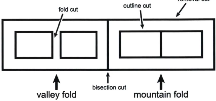
3-4 Example pattern to be laser cut. A positive and negative pattern corresponding to the front and back of the origami design is cut into a self-folding sheet. Fold cuts are designed to allow self-folding to commence in the proper areas. Outline cuts are the outer extremes of the self-folding structure. The bisection cut divides the positive and negative pattern. The removal cut aids in removing the post-cut pattern from the self-folding sheet. It also aids in alignment when both sides of the pattern are combined together. . . . . 41
3-5 Folding mechanism. When the unfolded sheet is exposed to heat, the heat-sensitive layer shrinks. This pulls the gap between the rigid layers on the valley fold side closed. The cut on the mountain fold side prevents the build up of stress within that rigid layer, which allows for more effective folding. . . . . 42
3-6 Experiment to confirm thermal boundary layer. To enable each robot to self-fold, we heat the robot with a thermoelectric module (Peltier element) from below. To test the limits of the distance a fold can be from the module to still self-fold, we arranged several self-folding latches in a line above the module. Each latch is around 4 mm in width. After about 3 minutes, we see that only the bottommost latch self-folds completely. Only the base of the next latch begins to self-fold, which could also be from conduction through the Mylar pylon holding all of the latches together. . . . . 44
3-7 An experimental robot self-folds. (a) The thermoelectric module is turned on. The magnet keeps the robot in place as it folds and acts as the base of the robot. This segment will always remain in contact with the thermoelectric module. (b) The pattern begins to fold. At first, all folds activate at roughly the same time. (c) Folds attached to the base folds are lifted into the air, outside of the self-folding temperature boundary. As the thermoelectric module continues to heat the air, the self-folding temperature boundary increases in distance from the thermoelectric module up to a point limited by the thermal boundary layer from convection. (d) The self-folding temperature boundary ex-pands enough to cause the rest of the robot to self-fold. (e) The robot finishes self-folding once all folds have spent adequate time within the
self-folding temperature boundary . . . . . 45
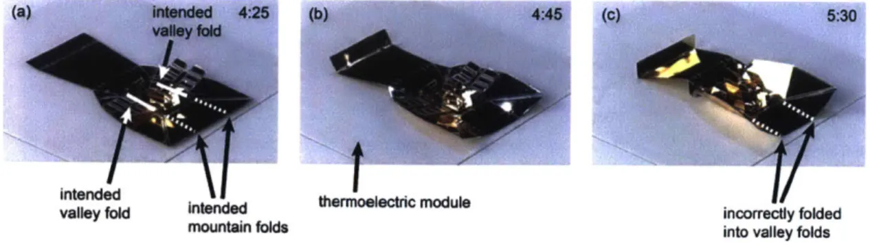
3-8 A robot self-folds incorrectly due to colinear mountain and valley folds.
(a) Wider valley folds are placed colinearly to smaller mountain folds.
(b) During self-folding, the valley folds exert a more powerful torque
about the colinear axis than the mountain folds, causing the mountain
fold to fold in reverse. (c) The robot buckles and folds incorrectly.
Additional heat only exacerbates the problem. . . . . 46
3-9 A robot self-folds incorrectly due to multiple successive valley folds. (a)
This robot is designed to self-fold into a wheel shape by rolling up from a flat sheet. (b) Each valley fold causes its attached segment to lift up, raising other valley folds up from the thermoelectric module. Even-tually, the successive valley folds escape the self-folding temperature boundary and are not able to heat up to the self-folding temperature.
(c) (d) and (e) show the folding sequence. . . . . 47
3-10 An example of controlled successive folds. (a) A wheel robot
pat-tern sits on a thermoelectric module. (b) The bottommost folds self-fold first, raising the topmost self-folds above the self-self-folding temperature boundary. (c) The bottom portion of the wheel completes folding while the top portion remains unfolded. (d) The wheel rolls over such that the topmost folds are closer to the thermoelectric module. (e) The topmost folds are now within the self-folding temperature boundary, allowing them to fold. (f) The wheel is finished self-folding. . . . . 48
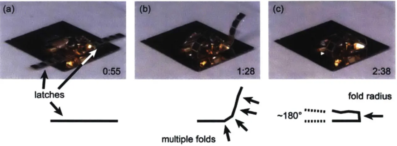
3-11 Implementing an approximately 1800 fold. (a) Our goal is to have the
latches fold completely around the center. (b) While 180' folds are difficult to implement using one fold, using multiple folds can result in an approximation of a 1800 fold for certain applications. (c) However, this results in a fold radius that is equal to the segment length. A certain segment length is needed to allow enough shrinkage from the heat-sensitive actuation layer. . . . . 49
3-12 An untethered, self-folding, walking, swimming robot. (a) The
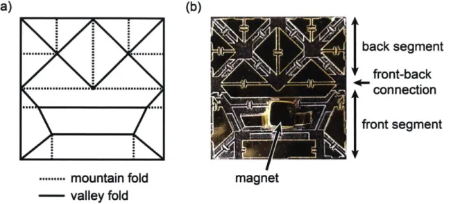
un-folded and un-folded states of our robot. The two front projections aid in walking and picking up objects. (b) A magnet is used for untethered actuation. (c) The front-back connection is one continuous fold, but it is bent at the centroid of the robot to secure the front half of the robot with the back half. This allows for the structural stability necessary for walking and carrying load. . . . . 50 3-13 (a) Origami pattern for our untethered, self-folding, walking, swimming
robot. (b) Self-folding translation of the origami pattern. The magnet is attached for actuation. . . . . 52
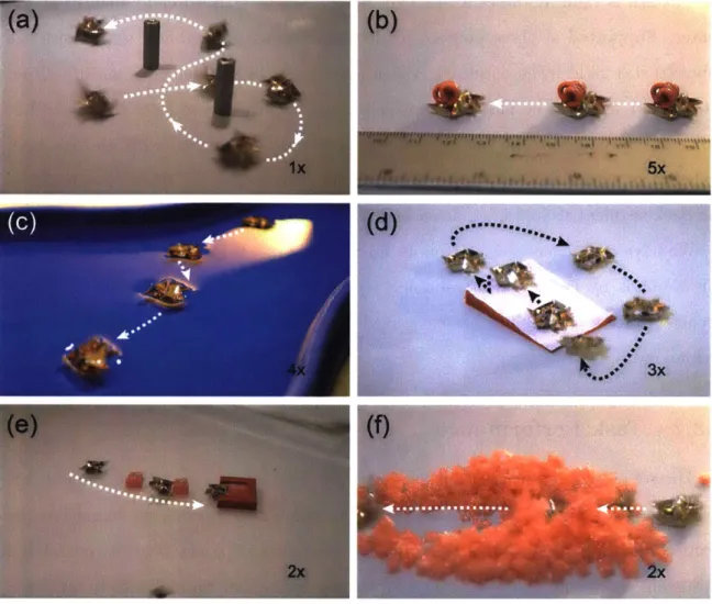
3-14 Task performances. (a) Walking around two pillars in a figure 8 pat-tern. (b) Carrying a load double its body weight. (c) Swimming in a pool of water. (d) Climbing a slope repeatedly. (e) Guiding a block to a goal. (f) Digging through a stack of blocks . . . . 54
4-1 Comparison between conventional robot and origami robot. (a) Con-ventional arm robot. The motor is made up of a magnet and copper coils. (b) Origami robot. The magnet and coils are seperated for
wire-less actuation. . . . . 56
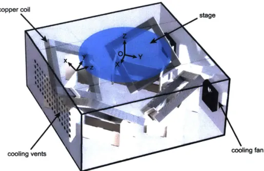
4-2 Electromagnetic coil system. The setup consists of 4 coils whose
cur-rents can be independently controlled to produce precise
electromag-netic fields in the stage above. . . . . 57
4-3 Layout of the system. . . . . 58
4-4 Single round loop of wire. The magnetic fiux density can be determined
at P by using Equation 4.2. . . . . 59
4-5 Diagram of the side of the electromagnetic coil setup labeled to
high-light the measurements required to derive the currents needed to
pro-duce a particular electromagnetic field at point P. . . . . 60
4-6 Diagram of the top of the electromagnetic coil setup labeled to highlight
the measurements required to derive the currents needed to produce a
particular electromagnetic field at point P. . . . . 61
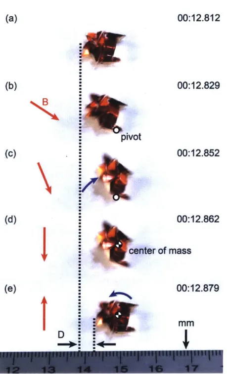
4-7 Stick-slip motion. (a) The robot in its resting position. (b) Magnetic field is applied at a low angle to slowly rotate the robot about its front
pivot. (c) A slightly higher angle magnetic field is applied, further
rotating the robot. (d) The robot is fully elevated. (e) A magnetic field is applied to rotate the robot counterclockwise. This causes the robot to slip from its front pivot, rotating instead about its center of mass. This completes one cycle of walking in which the robot has
moved a distance D from its original location. By repeating these
phases at high frequency, the robot is able to controllably walk on a
plane. . . . . 65
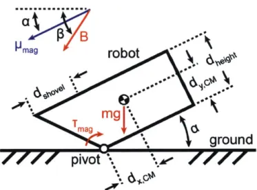
4-8 Diagram of robot during the first phase of slip-stick motion. In this phase, the center of mass of the robot moves forward; in the second phase, the robot rotates in the opposite direction about the center of mass, effectively moving forward the distance that the center of mass
has traveled in the first phase. . . . . 66
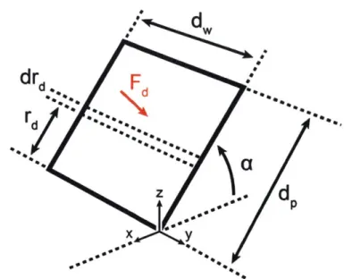
4-9 Approximated drag profile of robot. The drag force acting on the robot
occurs along its length as the body rotates about the front pivot. The robot can be modeled as a flat plate, and using integration, we can
find the total drag torque acting on the robot. . . . . 67
4-10 Robot Angle (degrees) vs Time (at 1 Hz and 1.25 mT applied magnetic field strength). The robot slowly inclines so that it rotates about its front pivots while sticking to the ground. The sudden decrease in angle causes the robot to rotate about its center of mass, completing a cycle of stick-slip motion. The high frequency components are the natural frequencies of the robot oscillating due to the applied magnetic force
(like a pendulum ). . . . . 71
4-11 Robot Angle (degrees) vs Time at (a) 10 Hz and 1.25 mT magnetic field strength. The applied magnetic frequency is in phase with the natural oscillations of the robot, resulting in clean stick-slip motion at
10 Hz. This results in a walking speed of 4.03 cm/s. (b) 20 Hz and
1.25 mT magnetic field strength. The applied magnetic frequency is too high to account for the natural oscillations and frequency response of the robot. Although a frequency of 20 Hz is applied, an apparent frequency of about 10 Hz is apparent, resulting in a walking speed of
6.63 cm /s. . . . . 73
4-12 Walking Speed vs Applied Magnetic Frequency (at magnetic field strength
of 0.5 m T ). . . . . 74
4-13 A magnet oriented in the direction of a linear mono-axial Hall effect
sensor. ... ... 75
4-14 Relation between x distance from sensor (with y = 0 and z = 15 mm) and the magnetic strength recorded from a Hall effect sensor. This data was used to verify calibration readings from the sensors as well as find the distance of a magnet from the sensor given the sensor readings. 76
4-15 Localization using Hall effect sensors. (a) There are 33 Hall effect
sensors that offer a 60 mm by 75 mm detectable area. The pattern allows trilateration to be performed within any of the triangles in the array. (b) Each sensor outputs a voltage proportional to the magnetic
field at the sensor. The voltages can be used to find the radii RA, RB,
and RC with which the location of the magnet can be found. . . . . . 79
4-16 Speed response of the robot given current input. Using this data, we were able to create a controller for the robot that applied appropriate
effort to the system . . . . . 83
4-17 Measured location vs actual location of the robot across the detectable area. The red crosses indicate the actual location of the robot. The blue dots represent 10 successive measurements of the estimated po-sition of the robot. The enlarged area at the top right of the graph shows a more detailed view of the spread of recorded measurements. The dotted grey circle is centered at the average of the 10 successive location measurements and has radius equal to the standard deviation
of the measurements. . . . ... . . . 85
4-18 Autonomous setpoint-based trajectory following. (a) Experiment 1: The robot navigates to a point at (10, 10) on the platform in 22 seconds.
(b) Experiment 2: The robot travels through 4 setpoints, tracing out
a diamond with corners at (40, 15), (65, 40), (40, 65), and (15, 40). . . 86
4-19 Using 3 Hall effect sensors, the magnet's position x and y as well as
its orientation 0 with respect to the sensors can be determined. Other
3D rotations are not considered, and the z position is kept fixed. . . . 88
4-20 Graph of the average test error at different points in the sensor trian-gle. The diameter of each red circle corresponds to the average error detected at that point. The points with the most error lie outside of
the triangle formed from the positions of our sensors. . . . . 97
4-21 Layout of the vision-based feedback control loop. . . . . 102
4-22 Autonomous movement around a circle. . . . . 103
4-23 Autonomous movement around an obstacle. A camera recognizes a placed object between the starting position of the robot and a pro-grammed goal. Using an RRT, the robot can navigate around the
obstacle to the goal autonomously. . . . . 107
5-1 Exoskeleton approach with untethered assembly. A single magnet and
Walk-bot exoskeleton can be combined into one Walk-bot using only electromagnetic control and heat-activated self-folding. Walk-bot can be combined with other exoskeletons to form different robots. Walk-bot can interface with one exoskeleton at a time, but Walk-bot can escape
from the exoskeleton by detaching through water-activated dissolving. 112
5-2 Walk-bot. (a) Unfolded exoskeleton with types of folds listed. (b)
Photo of unfolded exoskeleton. (c) Dimensions of Walk-bot. (d) Photo
of W alk-bot. . . . . 113
5-3 Walk-bot folding. (a) A magnet is rolled onto Walk-bot exoskeleton
using electromagnetic control. (b)-(f) Walk-bot self-folds. . . . . 114
5-4 Scaled walk-bot. (a) Unfolded exoskeleton with types of folds listed.
(b) Photo of unfolded exoskeleton. (c) Dimensions of Scaled walk-bot.
(d) Photo of Scaled walk-bot. . . . . 116
5-5 Full cycle of exoskeleton concept with Walk-bot and Scaled walk-bot. (a) A magnet is guided to the first exoskeleton. (b) The magnet is aligned. The exoskeleton encloses the magnet to become Walk-bot, which then walks off to the second exoskeleton. (c) Walk-bot aligns on top of the second exoskeleton. This exoskeleton's docking module latches onto Walk-bot while the exoskeleton self-folds. This results in a transformation into Scaled walk-bot. (d) Scaled walk-bot walks to a water pool and dives in. After about 5 min, the docking module dissolves. bot escapes the discarded exoskeleton intact. (e) bot emerges from the pool and walks to the center of the stage. Walk-bot is now capable of using other exoskeletons to grant it a variety of
on-demand capabilities. . . . . 117
5-6 Wheel-bot. (a) Unfolded exoskeleton with types of folds listed. (b)
Photo of unfolded exoskeleton. (c) Dimensions of Wheel-bot. (d)
Photo of W heel-bot. . . . . 120
5-7 Wheel-bot folding. (a) Walk-bot is guided to Wheel-bot exoskeleton
using electromagnetic control. (b)-(e) Wheel-bot partially self-folds.
(f) Wheel-bot is rolled so that its top segments can self-fold. (g)
Fin-ished W heel-bot. . . . . 121
5-8 Boat-bot. (a) Unfolded exoskeleton with types of folds listed. (b)
Photo of unfolded exoskeleton. (c) Dimensions of Boat-bot. (d) Photo
of B oat-bot. . . . . 122
5-9 Boat-bot folding. (a) Walk-bot is guided to Boat-bot exoskeleton using
electromagnetic control. (b)-(e) Boat-bot self-folds. (f) Boat-bot uses
slip-stick motion to walk to a pool, where it can swim and float. . . . 123
5-10 Glider-bot. (a) Unfolded exoskeleton with contraction gaps listed. (b)
Photo of unfolded exoskeleton. (c) Dimensions of Glider-bot. (d)
Photo of Glider-bot. . . . . 125 19
5-11 Glider-bot folding. (a) Walk-bot is guided to Glider-bot exoskele-ton with electromagnetic control. (b) Self-contracting tendons cause Glider-bot to bend into the appropriate wing shape. (c) Finished Glider-bot, ready for flight . . . . 126
5-12 Wing profile of Glider-bot. Self-contracting tendons pull a flat sheet of Mylar into a rigid wing structure . . . . 127 5-13 Test flight of Glider-bot. . . . . 128
6-1 Reconfiguration of the origami robot. (a) The robot begins in a com-pact pill form for easy swallowing and transportation to the stomach via ingestion. (b)-(e) The ice pill melts, revealing the inner robot. (f) The deployed robot completely unfolds from the pill. Its deployed form enables it to walk and cover a large area for targeted drug delivery. . 134
6-2 Removing the battery. The pill with the enclosed robot is swallowed and travels down the esophagus into the stomach. The pill is rolled to the button battery and attaches via magnetic attraction. The button battery is 'pulled out of the wound, preventing any more serious burning from occuring. . . . . 135 6-3 Delivering a targeted drug. After the robot from Figure 6-2 is removed
from the body, another pill-encased origami robot is swallowed. The pill melts inside the stomach, deploying the full origami robot. The robot walks to the wound site via stick-slip motion and sits on the wound. There, the included drug delivery layer in the robot's structure dissolves, aiding the healing of the wound. . . . . 136 A-1 Untethered origami robot that can walk and swim. (Top Left) Design
pattern. (Top Right) 3D view. (Bottom) 6 views of the robot. . ... 160 A-2 Walk-bot. (Top Left) Design pattern. (Top Right) 3D view. (Bottom)
6 views of the robot. . . . . 161 A-3 Scaled walk-bot exoskeleton. (Top Left) Design pattern. (Top Right)
3D view. (Bottom) 6 views of the robot. . . . . 162
A-4 Boat-bot exoskeleton. (Top Left) Design pattern. (Top Right) 3D
view. (Bottom) 6 views of the robot. . . . . 163
A-5 Wheel-bot exoskeleton. (Top Left) Design pattern. (Top Right) 3D
view. (Bottom) 6 views of the robot. . . . . 164
A-6 Glider-bot exoskeleton. (Top Left) Design pattern. (Top Right) 3D
view. (Bottom) 6 views of the robot. . . . . 165
List of Tables
4.1 Sample of Pre-Processed Data Points . . . . 92
4.2 Training Error for Each Kernel . . . . 99
4.3 Validation Error for Each Kernel . . . . 99
4.4 Testing Error for Each Kernel . . . . 99
4.5 Sample of Predicted Test Data . . . . 100
4.6 Predicted Special Data . . . . 101
5.1 Scaled walk-bot experimental successes and failures (5 trials) . . . . . 118
5.2 Wheel-bot experimental successes and failures (5 trials) . . . . 121
5.3 Boat-bot experimental successes and failures (5 trials) . . . . 124
5.4 Glider-bot experimental successes and failures (5 trials) ... 127
Chapter 1
Introduction
1.1
Motivation
The example of biology has provided humankind with the inspiration to develop technology that can meet and even overcome biology's advanced state of being with our shared environment. People were inspired to fly from the birds and insects who have soared through the air for millions of years. Art and aesthetics has taken example from the symmetry and chaos of life on Earth. In the present day, we seek to imitate life itself through the advancement of robotics, in effect creating artificial animals responsive to their environment with the ability to perform complex sets of tasks.
An animal can walk through the woods without knowing the complexity of a single step, yet the amount of research that humankind has engaged in to discover these secrets has been profound. As the complexity of robotics approaches the example of biology, scientists and researchers have relished in the success of advancement while still wondering why we are still so far away.
Millions of species of life exist on earth in the present day, and millions more have existed throughout the course of history. Each of these organisms evolved to be contrastingly robust in the face of uncertainty, yet specific in its manipulation of the surrounding environment. Even organisms amongst the same species have phenotypic diversity in response to the environment in which they reside. In biology, life is almost trivial to create. In robotics, it is still of the utmost difficulty.
At the present moment, biology still has a fundamental advantage in its sheer distributed nature. While technology has augmented biology and advanced our ma-nipulation of the environment around us in ways that biology simply cannot, the means to produce technology, and subsequently robots, is still far behind its source. To attain replication, the ability to disperse technology over space, technology still re-lies on a process that is hundreds of years old: manufacturing. Biology has provided an example whose robustness has been proven over hundreds of millions of years:
self-replication, or the ability to self-assemble.
In humans, self-assembly allows a single cell to transform into trillions of cells, each with specialized purposes coordinated with each other to survive as a single, complex organism. Animals have evolved relatively quickly because of the ease of their manufacture. So, what if robotics could achieve this same feat? How can robots achieve this same degree of specialty to environment in a world of technology that prioritizes mass production and scale?
1.2
A Cambrian Explosion of Robotics
514 million years ago, the Cambrian explosion gave rise to most major animal phyla throughout Earth, including most phyla present today. Before this period of roughly 80 million years, life had existed only as unicellular and simple multicellular lifeforms for nearly 4 billion years [5]. To this day, a range of theories exist to explain why this event occured. One prominent theory [61 proposes that, during this period, animal development advanced such that a wide variety of phenotypes could be ex-plored from a relatively small level of base genes and materials. Despite using the same cells, a great variety of animal body plans were generated through the evolution of development itself.
Thus, we ask the question: could a Cambrian explosion-like event occur again, except this time in the field of robotics?
Our motivation lies in advancing the developmental process of robots. Currently, robots are very specificly made. Many robots are designed painstakingly around a very
specific task in a very specific environment. Custom robotic parts are meticulously machined, and they're unique physical characteristics such as weight, dimensions, and inertial properties are diligently recorded for use in inverse kinematics, path planning, and programming.
How can we learn from the example of biology?
One answer is that we could create robots from universal parts, just as animals
are created from universal cells. Our goal would be to make robot development
trivial such that robotic applications could explode in use. Many methods have been proposed to do this: 3D printing is one avenue that has made manufacturing custom
parts easy from a universal plastic. But when multiple parts are created for one
assembly, how can that assembly be put together?
Once again, we look at the example of biology, specifically developmental biology. Cells self-replicate and self-categorize, giving rise to different structures on the animal that are all coordinated as one organism. We could apply this same idea of self-assembly to robotics, allowing a robot to be made from a universal material and subsequently self-assemble on-the-spot for use in its predisposed task.
Making it easier to develop complex robots rapidly and inexpensively may allow robotics to flourish in the future, just as animals flourished in the past. In this work, we propose one method to do this: create robots that can be made from a universal material and self-fold into structures that can be controlled to do tasks specific to their 3D morphology.
In the next chapter, we explore related work in the fields of robotic self-assembly and control. We subsequently show how this leads to the development of our own method, which we will detail at length in this thesis.
Chapter 2
Related Work
The concept of origami robots arose as one of many areas of research in the field of self-assembly, which in turn was influenced by the origins of life. Complex structures and dynamic lifeforms emerge from simple molecules, modules, cells, and shapes in
elegant ways [7]. A human, made of parts on the order of 101, can self-assemble in
less than a year. In contrast, today's smartphones are made from about 102 parts
in a few days (about 10-2 years). Comparing orders of magnitude, we see nature's
advantage: a billion times more parts complexly organized! Even when we consider production scale (10'), the mechanical mastery of nature is evident in its ability to self-assemble from elemental components.
Robotics has primarily adopted conventional production methods: one part is for one task, and one robot is for one purpose. This specialized method offers numerous practical advantages with our state of technology. However, applying the concept of self-assembly to robotics opens a whole new avenue to explore.
2.1
Self-Assembling Robots
Murata and Kurokawa share with us the advantages of self-reconfigurable robots
that mirror the benefits of origami robotics [8]. At the highest level, the ultimate
purpose of self-reconfigurable and self-assembling robots is to offer the same flexibility in function as life itself: the ability to engage in morphogenesis, self-repair, and
reproduction. Robots in this field also offer the unique ability to scale immensely, so that hundreds if not thousands of robots can be made to serve some task. Scaling can increase the robustness of robots as a whole unit. Emergent behaviors can also be observed when enough self-assembling robots are used at once, which offers a level
of coordination and flexibility that is only rivaled in biological systems [9J.
Bio-inspiration also serves to increase the adaptability and robustness of robots in contrast to hardware designed for very specific tasks in very specific circumstances
[101. For example, a great variety of locomotion gaits has been explored in
self-assembling robots [11] [12], something that wouldn't be possible with a robot solely intended for one method of transportation.
In the field of self-assembling robotics, the bio-inspired modular approach has been explored in great detail. Modular robots are based on the idea of biological cells. In biology, the cell forms the basis for complex biological organisms and their systems. The promise of modular robotics originates from this premise: several, low-cost modular robotic units can self-assemble into a robot with morphological function adept to the task required [13].
Several hardware implementations of modular (or cellular) robotics have been pro-posed. Many systems are based on cube-shaped cells with a docking system that con-nects each module to one another. Other shapes have been researched, including
tri-angles that can assemble into hexagons [14], . Mechanical [15] [16] [17] [181, magnetic
[19], electromagnetic [201, hybrid mechanical [21], and hybrid magnetic-SMA [22] docking systems are the most popular docking methods. Various methods
for assembling these robots into usable structures have also been investigated [23]. However, research on modular robotics has revealed several challenges and limi-tations that may be intrinsic to the current hardware platforms used. The systems referenced earlier are all on the cm scale, and thus certain scaling relationships with re-gards to energy consumption discourage these robots from being used for the ultimate purpose of modular robotics. Many state-of-the-art modular robotic units are com-plex in hardware and push the limitations of current motor and electric technology, especially in regards to docking between each other and the act of reconfiguration
[24]. This complexity has also prevented the mass manufacture of such modules.
Currently, the number of units is limited at order of magnitude of 101 [13]. While
computation [25], mathematical approaches [26], and construction methods [27] have advanced far beyond the limits of modular hardware, this approach is still far from the goals of self-assembling robots.
To this end, a new method of self-assembly has been proposed: the concept of
self-folding.
2.2
Self-Folding
Robots
Self-reconfiguration on the cellular and molecular level offers the most low level method for creating adaptable structures in dynamic environments. However, current complexity in technology has made this task difficult. Stepping up a level, we see that a great many self-reconfigurations can occur in which the structure is most observably important, rather than the innate molecular construction of the materials. Self-folding is one such self-reconfiguration.
Programmable structures from a single sheet of material have been demonstrated
[28], enabling the versatility sought from modular methods. Self-folding also can ease
the production of certain items at a small scale [29], which is one the main goals of self-assemby in general. Self-folding has been achieved through many methods, including thermal activation [30] [31], electric fields [32], soft lithography [33], hydrogels [34],
magnetism [35], lasers [36], light absorption [37], air bladders [38] [39], and shape
memory composites [40], which include heat-sensitive actuation materials [41] [42]
[43].
The ability to make such structures predictably and with structural integrity has also been investigated in depth [44] [45]. Algorithms have been proposed to transform
3D shapes into patterns that can self-fold from 2D universal sheets [46] [47], and the
idea of having software that allows for computation of complex, self-folding devices has proven particularly advanced [48].
Proposed structures and applications have been numerous. Self-folding has been
used to make mechanical [49] and electronic [43] [42] components, structural elements
[50], sensors [511, and complex machinery such as quadroters [52] and telemanipulation
devices [53]. In particular, applications in robotics have been expansive, including the design of inchworms [54], crawlers [55], insects [56], wheels [57], pinchers [58], extenders [59], legs, and manipulators [60]. Most of these designs are origami-inspired, the idea that the ancient Japanese art of paper-folding could be used as a basis to create complex 3D objects from 2D sheets. The idea has been extended to the idea of printable robotics: a robot could be built on demand for any task using input from a user and computational construction to "print" a robot from a sheet of universal
material, then having it self-fold on the spot [52] [48] [39] [54] [49]. This would
fulfil the goal of making robots available on a broad scale, due to their ability to be manufactured rapidly and inexpensively.
Yet, a broad question remains. While most research has engaged with the idea of producing robot structures through origami, integrating actuators, sensors, and intelligence has remained a challenge in this field. Current methods of robot actuation
include motors [54] [60] [59] [61], air bladders [39], and shape memory alloy [62]. All
of these require either the complex integration of the components inside the robot itself, or a tether that connects the robots to a computer and power supply. The simplified nature of the formation of the robotic structure directly contrasts with the complexity of this approach.
With this in mind, magnetic actuation and sensing has been proposed as an al-ternative approach.
2.3
Magnetic Actuation and Sensing
Using wireless magnetic control has been of great interest to research for applica-tions on the small and micro-scale, especially with regards to biomedical applicaapplica-tions
[631 [64] [651. Most of these systems use a permanent magnet or magnetic material,
attached to an end-effector, actuated by an external magnetic [66] or electromagnetic
[67] [68] [69] [70] system. The majority of these systems are comprised of several
tromagnetic coils that completely enclose the actuation area, making the workspace of these systems very small. Independent actuation of microrobots has been demon-strated [71]. Movement in microrobots has been shown through gradient [71] and torque-based methods [671, including oscillitory motion for walking [721 [70],
cork-screw thrust in liquids [73], and full 6 DoF control [74]. Control of microrobots using
human operators [65] [75] and computer vision [76] [77] has been proposed, although this is limited to situations where the robot can inherently be seen.
As an alternative to computer vision, localizing the magnet using measurements
of its magnetic field at different locations has also been proposed. Nearly all of
these methods utilize Hall effect sensors, which output a voltage in proportion to the magnetic field magnitude and direction at the sensor location [78] [79] [80] [81]. Other methods utilize magnetic resonance [82], permanent magnets [83], and other methods [84] for localization. Applications of this approach have been medical in nature (due to lack of other alternatives in this approach [85]). Researchers have used Hall effect sensors to track tongue movements for speech pathology [86]. However, the primary application has been wireless capsule endoscopes [87] [88] [80] [89] [79]. Research has even delved into optimal sensor locations for this application [90].
With these previous studies in mind, research has yet to combine the on-the-spot manufacturing capabilities of self-folding technology with instant actuation and closed-loop response to complete a demonstration of an untethered, self-folding robot.
2.4
Thesis Contributions
Our goal is to create robots that can be manufactured rapidly and inexpensively. To build upon the state of the art in self-assembling robotics, we sought to build robots that could be made from a universal sheet, self-folded, and actuated in an untethered fashion. Thus, our thesis contributions are summarized by the following:
1. We explore the self-folding process used in [421 [43] to design an untethered,
miniature origami robot that can walk, swim, and perform a series of versatile tasks on its scale.
2. We overview best design practices when using this self-folding process to design
self-folding origami.
3. We detail the electromagnetic coil system used. to control our robots in an
untethered fashion.
4. We propose a method of centimeter-scale robot locomotion called stick-slip mo-tion, and we characterize robotic movement by analyzing this motion.
5. We investigate magnetic feedback control through the use of magnetic
field-sensitive Hall effect sensors to localize our robots, utilizing both trilateration and a machine learning approach to localize the magnet.
6. We implement autonomous movement and closed-loop feedback control using
magnetic localization.
7. We show more complex motion planning using visual feedback control.
8. We demonstrate application of the self-folding robot approach to a series of
robots that can assemble as a structure and as multi-robot units. These robots can walk, swim, and fly.
9. We apply self-folding origami robots in a medical setting. Using an origami
robot, we can remove a foreign object from a wound in the gastrointestinal system. Then, we can deliver a targeted drug to the wound using a subsequent origami robot.
In summary, we seek to make a robot rapidly and inexpensively, using self-folding technology, that we then actuate using an exterior electromagnetic coil system and lo-calize using a combination of magnetic sensing and visual recognition. This will allow a complete demonstration of autonomous movement and applications in appropriate settings that we can use to show the promise of our method.
2.5
Thesis Outline
In Chapter 1, we detailed our motivations in studying self-assembly in robotics. In this chapter, we followed up with an overview of related work in the fields of self-assembly, self-assembling robotics, self-folding robotcs, magnetic control, and mag-netic sensing and localization. The following chapters comprise the main contributions of this thesis.
Chapter 3 is centered on origami robot design. We investigate a self-folding process based on a heat-sensitive actuation layer that, when heated, pulls adjacent faces of material such that a fold results. We gained much experience working with this process, and so we present best design practices to use when working with this method. Using these guides and with the motivation to create a robot using this method, we present an untethered miniature origami robot. This robot can walk, swim, move blocks, dig, and more, all while being remotely controlled by an electromagnetic coil system detailed in the next chapter.
Chapter 4 is focused on origami robot control. The electromagnetic coil system that we use for all of our robot actuation is explained in detail, including how we generate precise magnetic fields in arbitrary directions. We explore stick-slip motion, the primary method of walking used by our robots, and we analyze the speed and frequency responses of a robot that moves using this method. We investigate magnetic feedback control by exploring Hall effect sensors, which are capable of detecting the
magnitude of magnetic field strength at their locations. We model the magnetic
field and use this information to create a system that can localize a magnet utilizing trilateration. We detail our Hall effect sensor localization setup and hardware. We show our controller that we use for autonomous locomotion, and we test the accuracy of our method and setup. We improve our Hall effect sensor-based localization method
by adding magnetic orientation sensing using a machine learning approach, and we
test the accuracy of this method as well. Finally, we demonstrate visual localization and feedback control of our robot that enables autonomous motion, including path planning and avoiding obstacles.
Chapter 5 investigates an application of origami robots: the exoskeleton approach. The idea is to allow a single robot to take on different morphologies for different tasks, in succession or in response to a particular environment. We demonstrate rolling a magnet on top of a self-folding pattern to construct Walk-bot, a miniature robot that can walk using stick-slip motion. This shows how our approach can be used to engage in untethered assembly as well as control. We show several different exoskeletons that Walk-bot can wear to enable size-scaled abilities, rolling, swimming, and flying. Finally, we demonstrate the ability to shed these exoskeletons, allowing Walk-bot to wear another exoskeleton of choice.
Chapter 6 explores another application of origami robots: the gastrointestinal system. An origami robot can be manufactured, rolled into a pill, swallowed, and deployed inside the stomach to remove a foreign object (in our case, a button battery, which can cause severe burn wounds and even death when inside the stomach). After the first origami robot is removed, a second identical origami robot can enter the stomach to deliver a targeted drug to the wound. The untethered actuation of the robot combined with its ability to be manufactured rapidly and inexpensively enables the robot to be applied in this way.
Chapter 7 is the conclusion of this thesis. Appendix A provides select origami robot designs and patterns. Appendix B lists the steps to manufacture a self-folding sheet and a complete origami robot from design and materials.
Chapter 3
Origami Robot Design
The design of origami robots is critical to their abilities. Just as animals draw different advantages from their respective morphologies, our robots' functionality is dependent on their design.
In this chapter, we detail our heat-activated self-folding process, including the fabrication of a universal self-folding base sheet and the characterization of the ther-moelectric module-based heating method that we use to self-fold our robots. We follow with the design process for origami robots, including information about best practices that we learned from experience. We conclude with an untethered, self-folding, walking, swimming robot (based on content from [1]) and go through the design and task performance of this particular robot.
3.1
Self-Folding Process
Our heat-activated self-folding method is based on a layered structure that consists of a heat-sensitive contraction layer sandwiched between two rigid layers that form the overall structure of the robot (see Figure 3-1). In our robots, we used polyvinyl chloride, PVC, for the heat-sensitive contraction layer and Mylar for the rigid layers. When heated, the contraction layer shrinks. By controlling where the contraction layer can shrink, we are able to induce folds in the layered structure. We can control where the contraction layer can shrink by cutting gaps into the rigid layers.
valley fold
structurallayer
(Mylar)+
I
r
-a e My ) +-w - silicone adhesive heat-sensitive -6-actuation layer (polyvinyl chloride)mountain fold
Figure 3-1: Structure of the self-folding sheet. The layered sheet is made from a rigid structural material (Mylar), a heat-sensitive layer that shrinks when exposed to high temperature (polyvinyl chloride), and silicone adhesive, which holds the structure together. For a given fold, the mountain fold corresponds to a cut in the structural layer. The valley fold corresponds to a gap in the structural layer.
The simplest fold, seen in Figure 3-3, can be made by cutting a gap on one rigid layer while making a cut along the gap on the other rigid layer. The gap allows the heat-sensitive layer to shrink in an unrestricted manner. The cut allows the structure to fold because it releases stress that will build on one side of the fold. Once heated, the structure will fold along the gap in the direction of the gap due to the contraction force of the heat-sensitive layer, which acts as a tendon along the constructed joint. If the gap is thin compared to the shrinking percentage of the heat-sensitive layer, then the fold will stop once mechanical contact occurs between both sides of the gap. Thus, it is possible to control the angle of the fold by adjusting the width of the gap. Once the gap becomes too wide, the angle becomes limited by the shrinking percentage of the heat-sensitive layer. By combining many of these gaps and cuts, it's possible to encode an origami structure into the layered structure.
3.1.1
Fabrication of Self-Folding Sheet
The fabrication process for our layered structure is presented in Figure 3-2. First, a pre-constructed layered structure is needed as basic material with which to construct the robot. A rigid sheet with non-permanent adhesive is attached to a sheet of Mylar. Subsequently, a sheet of silicone adhesive is attached to the other side of the Mylar. The silicone adhesive has a protective layer on one side, resulting in a four layer
(1) I (2) II (3) (4) (5) silicone adhesiv sructural layer (my, laser a protective layer
I
lar) supportive layer cutsI-I
\
gap__01. 11
heat-sensitive actuation layer (polyvinyl chloride) U mountain fold valley foldFigure 3-2: Fabrication process for self-folding structure. (1) A protective layer, silicone adhesive, structural layer, and a supportive layer are combined into one 4-layered structure. (2) A laser cuts the pattern into the sheet. The protective layer prevents the silicone adhesive from becoming destroyed. Both a positive and negative of the pattern are cut side-by-side on the sheet: for every moutain fold on one side, the laser cuts a valley fold on the other side, and vice versa. (3) The gap material and surrounding material are removed. The protective layer of the structure that we want in our final design is removed to expose the silicone adhesive. (4) The heat-sensitive actuation layer, PVC, is attached to one side of the pattern, either positive or negative. This half of the pattern is removed from the supportive layer.
(5) The removed pattern is aligned with the other side of the design and affixed. The
completed self-folding structure is removed, ready to be self-folded.
unfolded
heat
folded
Figure 3-3: Folding mechanism. When the unfolded sheet is exposed to heat, the heat-sensitive layer shrinks. This pulls the gap between the rigid layers on the valley fold side closed. The cut on the mountain fold side prevents the build up of stress within that rigid layer, which allows for more effective folding.
structure consisiting of the rigid underside, Mylar, silicone adhesive, and protective layer.
A crease pattern is designed based on an origami structure. The mountain and
valley folds are marked so that the gaps and cuts can be constructed in the right areas. The crease pattern is mirrored such that the front and back of the pattern becomes visible (since two rigid layers are required, one for each side of the heat-sensitive layer). Gaps and cuts are overlayed upon the crease patterns such that a
particular fold has a gap on one side and a cut on the other side (see Figure 3-4).
A laser cutter is used to cut the crease pattern into the basic four-layered
struc-ture described above. The intensity of the laser is precisely set to cut through the protective layer, silicone adhesive, and Mylar layer, but not the rigid underside. If the laser were to cut through all four layers, the pattern would fall apart. If the laser were to cut through the Mylar incompletely, then eventual folding of the origami structure would be unpredictable. A vinyl cutter can also be used to cut the structure out
by setting the blade cutting depth to the precise thickness of the protective layer,
removal cut foid cut outline cut
t
t
bisection cut
valley fold
mountain fold
Figure 3-4: Example pattern to be laser cut. A positive and negative pattern corre-sponding to the front and back of the origami design is cut into a self-folding sheet. Fold cuts are designed to allow self-folding to commence in the proper areas. Outline cuts are the outer extremes of the self-folding structure. The bisection cut divides the positive and negative pattern. The removal cut aids in removing the post-cut pattern from the self-folding sheet. It also aids in alignment when both sides of the pattern are combined together.
manufacturing.
Once the pattern is completely etched, the pattern is cut out of the basic structure. The protective layer is removed from each segment of the origami pattern. Segments that consists of gaps and borders are not removed because we want these to be material-free in the final layered structure. Once the silicone adhesive is exposed, one side of the pattern is attached to the heat-sensitive layer. The other side of the pattern is folded over the other side of the heat-sensitive layer such that both patterns align precisely over each other. The rigid underside is removed from both sides, leaving the origami pattern attached to both sides of the heat-sensitive layer, forming the two rigid layers described above. Finally, the pattern is cut out, leaving a finished origami pattern ready to be self-folded.
3.1.2
Thermoelectric Module Heating
To implement thermally-activated self-folding, a number of methods can be used. The robot can be immersed in hot water. The robot can also be placed inside an oven.
Vair
thermal boundary layer
y
/+
X wall
thermoelectric module
Figure 3-5: Folding mechanism. When the unfolded sheet is exposed to heat, the heat-sensitive layer shrinks. This pulls the gap between the rigid layers on the valley fold side closed. The cut on the mountain fold side prevents the build up of stress within that rigid layer, which allows for more effective folding.
The only constraint is that the thermally-activated actuation layer must be heated to a temperature within the deformation temperature and the melting temperature. If the layer is heated beyond the melting temperature, the plastic will begin to liquify and vaporize, rendering the robot useless.
While immersing the robot in hot water or putting the robot in an oven may provide relatively universal heating, the robot must be physically removed to enable any kind of actuation. Our design goal was to enable immediate actuation after self-folding completed. Thus, we used a thermoelectric module to provide heating to the robot. The flat thermoelectric module allows the robot to move off of the heating area once the self-folding process is complete. The compactness of the thermoelectric module also enabled us to integrate the device into the electromagnetic coil platform with ease, enabling self-folding and actuation to be done without physical human intervention.
Since the heating is only radiated from the thermoelectric module itself, the ac-tuation layer is heated only on one side through convection through the air and conduction from the bottom of the robot.