DATE: A Framework for Supporting Design
Artifact Tracking and Evolution
by
Christopher R. Vincent
Submitted to the Department of Electrical Engineering and Computer Science
in Partial Fulfillment of the Requirements for the Degrees of
Bachelor of Science in Electrical Engineering and Computer Science
and Master of Engineering in Electrical Engineering and Computer Science
at the Massachusetts Institute of Technology
May 21, 1999
Copyright @ 1999 Christopher R. Vincent. All rights reserved.
The author hereby grants to M.I.T. permission to reproduce and
distribute publicly paper and electronic copies of this thesis
and to grant others the right to do so.
Author ...
. .-... ...Department of Electrical Engineering and Computer Science
May 21, 1999
Certified by ...
...
...
...Howard E. Shrobe
Thesis Supervisor
2
Accepted by
.
. .... . ..
.M
.d .E
./2. ...\ rth . Smit...Chairmd on Arthu
Smith
DATE: A Framework for Supporting Design
Artifact Tracking and Evolution
by
Christopher R. Vincent
Submitted to the Department of Electrical Engineering and Computer Science
in Partial Fulfillment of the Requirements for the Degrees of
Bachelor of Science in Electrical Engineering and Computer Science
and Master of Engineering in Electrical Engineering and Computer Science
at the Massachusetts Institute of Technology
May 21, 1999
ABSTRACT
The DATE system supports collaborative engineering by providing a framework for capturing,
archiving, evolving, and navigating design artifacts. For a software engineering effort, this includes
source code, comments, test cases, documentation, and discussions between developers. Archives of
design artifacts are rooted in a source code representation which addresses functional decomposition,
configuration management, and version tracking. Users extend archives by operating on resources,
asserting relationships (links) and attaching annotations such as documentation, observations, and
design rationale. An initial implementation allows geographically distributed developers to navigate
and extend a shared project archive using networked client interfaces. Supporting technologies are
developed for leveraging object storage services (e.g. databases, file systems) and for efficiently
sharing data across network and programming language boundaries.
Thesis Supervisor: Howard E. Shrobe
Acknowledgements
Appreciation and thanks to Carolynn Bischoff, Andrew Blumberg, Sue Felshin, Roger Hurwitz,
Robert Laddaga, John Mallery, Kalman R6ti, Howard Shrobe, and Paul and Linda Vincent.
This paper describes research done at the Artificial Intelligence Laboratory of the Massachusetts
Institute of Technology. Support for the MIT Artificial Intelligence Laboratory's artificial intelligence
research is provided in part by the Defense Advanced Research Projects Agency of the Department
of Defense under contract number F30602-97-2-0013.
Contents
1 Overview
8
2 Design Artifacts
10
2.1
Artifacts Defined . . . .
10
2.2 Evolution of Designs . . . .
.
. . . . .
.
.
.
. . .
10
3 Archive Framework
11
3.1
Design Goals . . . .
. . .. .
.
.
.
. - - - - .
. . .
11
3.2
Resources . . . .
13
3.2.1
Granularity: Code Units . . . .
13
3.2.2
Configuration Management: Implementations . . . .
13
3.2.3
Representing Time: Versions . . . .. .
.. .
14
3.3
Application to Programming Languages . . . .
14
3.4 Links . . . - - - .
. .
.
. . - - - - -.
. . . .
15
3.4.1
Language Semantics . . . .
15
3.4.2
Documentation and Specification . . . .
15
3.4.3
Annotation . . . .
16
3.4.4
Testing and Verification . . . ..
. . . .
17
3.5 Collections
...
...
..
.
.-.-.-.-.-.-.-
.17
3.6 Resource Indexing . . . .
18
4 User Interface
19
4.1
Design Goals . . . .
. . - - .
.
. . .
.
19
4.1.1
Fine-Grained Configuration Management . . . .
19
4.1.2
Multidimensional Source Code . . . .
20
4.1.3
Integration of Tools . . . .
21
4.2 Interface Components . . . .
21
4.2.1
Configuration . . . .
21
4.2.2
Archive Navigator . . . .
21
4.2.3
Annotation Editor . . . .
24
4.3
Editing Source Code . . . .
25
5 Persistent Object Support
26
5.1
Design Goals . . . .
26
5.1.1
Integration of Storage Mechanisms . . . .
26
5.1.2
Bounding Interaction . . . .
27
5.1.3
Programming Interface . . . .
27
5.2
Storage Mechanisms . . . .
28
5.2.1
allocate-storage-mechanism . . . .
28
5.2.2
optimize-storage-mechanism . . . .
28
5.2.3
*default-storage-mechanism*
. . . .
28
5.2.4
*supported-storage-mechanisms*
. . . .
29
5.3 Identifiers . . . .
29
5.4 Persistent Classes . . . .
- - . .
. . .
. ..
. .
29
5.4.1
define-persistent-class . . . .
30
5.4.2
make-persistent-instance . . . .
30
5.4.3
save-object . . . .
. . . . .
.
.
- - .
. . . .
30
5.4.4
save-objects . . . .
30
5.4.5
object-saved-p . . . .
31
5.4.6
object-modified-p . . . .
31
5.4.7
object-cached-p . . . .
31
5.4.8
object-identifier . . . .
31
5.4.9 load-object . . . .
31
5.4.10 save-root-object . . . .
32
5.4.11 load-root-object
. . . .
32
5.5
Example . . . - - - - .
- - - .
. .
32
6 Distributed Object Management
35
6.1
Design Goals ...
...
.
...
35
6.2 Remote Method Invocation ...
...
36
6.3 Lisp Interface . . . - - .
. .
. .
. .
..
. . . .
37
6.3.1
with-java-serialization-output . . . .
38
6.3.2
write-object . . . .
38
6.3.3
output-byte-count . . . .
38
6.3.4
with-java-serialization-input . . . .
38
6.3.5
read-object . . . .
38
6.3.6
input-byte-count . . . .
39
6.3.7
instance-for-serialization . . . .
39
6.3.8
generate-java-source-for-class . . . .
39
6.3.9
flush-cached-class-mappings . . . .
39
6.4 Java Interface . . . .
.
- - - - .
. .
39
6.5 Examples . . . .
40
6.5.1
Primitive Lisp Types . . . .
40
6.5.2
CLOS Objects . . . .
. .
. .
41
7 Evaluation
43
7.1
Archive Framework . . . .
. . . .
43
7.2
Persistent and Distributed Object Support . . . .
43
8 Future Work
45
8.1
Building a Navigation Toolkit . . . .
45
8.2
Software Engineering Applications . . . .
45
8.2.1
Monitoring Performance . . . .
46
8.2.2
Statistical Profiling . . . .
46
8.2.3
Exception Handling . . . .
46
8.3
Archive Framework . . . .. . .
. .
. .
. .
.
47
8.3.1
Link Types . . . .
- - .
. ..
47
8.3.2
Resource Indexing . . . .
.
.
.
47
8.3.3
Users
. . . ..
. . .
.
.
.
47
8.3.4
Low-Level Source Code Representations . . . .
48
8.3.5
Application to Programming Languages . . . .
48
8.4 Network Interface . . . .
48
8.4.1
Managing Clients . . . .
48
8.4.2
Leveraging HTTP . . . .
. .
49
8.5 User Interface . . . .
.. . .
49
8.5.1
Constraint-Based Collections . . . .
.
49
8.5.2
Code Unit Lookup . . . .
.
49
8.5.3
Archive Interface . . . .. .
49
8.6
Persistent Object Support . . . .
50
8.6.1
Tracking Class Evolution . . . .
50
8.6.2
Identifiers . . . .
50
8.6.3
Storage Mechanisms . . . .
50
8.6.4
Root Objects . . . .
51
8.7 Distributed Object Management
. . . .
51
8.7.1
Java RMI . . . .
51
8.7.2
CLOS Inheritance . . . .
51
9 Related Research
52
9.1
Gwydion Project . . . .
52
9.2
Global Cooperative Computing . . . .
53
9.3 Software Architecture . . . .
53
11 Source Code
58
11.1 Shared Utilities . . . .
58
11.1.1 code/cds-util/package.lisp . . . .
58
11.1.2 code/cds-util/util.lisp
. . . .
59
11.1.3 code/platform/mcl/cds-util/package.lisp . . . .
59
11.1.4 code/platform/mcl/cds-util/weak-hash-table.lisp
. . . .
60
11.2 Java Object Serialization Protocol . . . .
60
11.2.1 code/java/package.lisp . . . .
60
11.2.2 code/java/serialization.lisp
. . . .
61
11.3 Persistent Object Support . . . .
80
11.3.1 code/pcs/bin-dumper.lisp . . . .
80
11.3.2 code/pcs/class-info.lisp
. . . .
90
11.3.3 code/pcs/class.lisp . . . . .
...
...
.
...
92
11.3.4 code/pcs/filesystem-storage.lisp . . . .
93
11.3.5 code/pcs/identifier.lisp . . . .
94
11.3.6 code/pcs/java-serialization.lisp . . . .
96
11.3.7 code/pcs/log-based-storage.lisp . . . .
97
11.3.8 code/pcs/make-load-form.lisp . . . 100
11.3.9 code/pcs/package.lisp . . . .
- . .
101
11.3.10code/pcs/serial-number.lisp . . . 102
11.3.11 code/pcs/storage-mechanism.lisp . . . .
103
11.3.12code/pcs/system.lisp . . . .
105
11.3.13 code/pcs/test.lisp
. . . ..
111
11.3.14 code/platform/genera/pcs/package.lisp
. . . .
112
11.3.15 code/platform/genera/pcs/serial-number.lisp . . . .
113
11.3.16 code/platform/genera/pcs/statice-storage.lisp . . . .
114
11.3.17 code/platform/genera/pcs/weak-hash-table.lisp . . . .
116
11.4 Archive Framework . . . .
116
11.4.1 code/cds/archive.lisp . . . 116
11.4.2 code/cds/class.lisp . . . 121
11.4.3 code/cds/code-archive.lisp . . . 129
11.4.4 code/cds/java-serialization.lisp
. . . 131
11.4.5 code/cds/lisp-code.lisp . . . 131
11.4.6 code/cds/lisp-parser.lisp . . . .
. . .
140
11.4.7 code/cds/package.lisp . . . 147
11.4.8 code/cds/test.lisp . . . 148
11.5 Network Interface . . . .
.
.
149
11.5.1 code/interface/object-server.lisp
. . . .
149
11.6 Configuration . . . .
151
11.6.1 configuration/cl-http/exports.lisp . . . .
151
11.6.2 configuration/platform/mcl/sysdcl.lisp . . . .
151
11.6.3 configuration/platform/mcl/translations.lisp . . . .
152
11.6.4 configuration/platform/mcl/cds/sysdcl.lisp
. . . .
152
11.6.5 configuration/platform/mcl/cds-util/sysdcl.lisp . . . .
153
11.6.6 configuration/platform/mcl/cl-http
/cl-http-init.lisp
. . . .
153
11.6.7 configuration/platform/mcl/interface/sysdcl.lisp
. . . .
153
11.6.8 configuration/platform/mcl/java/sysdcl.lisp . . . 154
11.6.9 configuration/platform/mcl/pcs/ configuration.lisp . . . 154
11.6.10 configuration/platform/mcl/pcs/sysdcl.lisp
. . . 155
11.7 Java Client . . . 155
11.7.1 code/java/AnnotationDialog.java . . . 155
11.7.2 code/java/ArchiveInterface.java . . . 158
11.7.3 code/java/CodeUnitPanel.java
. . . 162
11.7.4 code/java/ConfigurationFrame.java . . . .
170
11.7.5 code/java/HistoryFrame.java . . . .
172
11.7.6 code/java/HistoryPanel.java . . . .
173
11.7.7 code/java/IdentifierListModel.java . . . ..
174
11.7.8 code/java/LinkPanel.java . . . .
175
11.7.9 code/java/Main.java . . . .
179
11.7.10 code/java/Navigator.java
. . .
.
. .
.
.
. . . .. . . .. . . . ...
. .. .
182
11.7.11 code/java/NavigatorPanel.java . . . 182
11.7.12 code/java/lisp/lang/Keyword.java
. . . 184
11.7.13 code/java/lisp/lang/LispObject.java . . . 185
11.7.14 code/java/lisp/lang/Symbol.java . . . .
185
11.8 Demonstration Archive . . . .
185
11.8.1 demo/archive-cl-http.lisp
. . . .
185
11.8.2 demo/build-server-image.lisp
. . . .
192
List of Figures
1 Overview of a collaborative software engineering support system. . . . . 92 Code archive resource structure. Arrows represent a one-to-many relationship. . . . 14
3 Client splash screen. . . . . 20
4 Client configuration window. . . . . 21
5 Archive navigator window. . . . . 22
6 (a) Archive and (b) interface representations of a discussion thread. . . . . 23
7 Annotation editor window . . . . . . ... 24
1
Overview
The DATE system supports collaborative engineering by providing a framework for capturing,
archiving, evolving, and navigating design artifacts. For a software engineering effort, this includes
source code, comments, test cases, documentation, and discussions between developers. Project
archives provide an environment for creating and manipulating such design artifacts, allowing the
integration of engineering support tools which have traditionally suffered from lack of a shared
project representation.
A prototype DATE implementation, consisting of about 8,000 lines of Common Lisp and Java
source code, provides an archive infrastructure targeting software engineering. A user interface
demonstrates source code navigation, editing, and annotation capabilities made possible by the
archive model. Supporting technologies are developed to enable system deployment over a
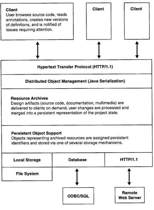
dis-tributed user base. Figure 1 illustrates the relationships between major DATE components, as
outlined below.
Section 3: Archive Framework Archives, implemented in Common Lisp as networked servers,
track the evolution of design artifacts generated by software engineering projects. At the core of the
framework is a source code representation which addresses functional decomposition, configuration
management, and version tracking. Users extend archives by operating on resources, asserting
relationships (links) and attaching annotations such as documentation, observations, and rationale.
The framework provides an intermediate level of representation, emphasizing support for design
evolution and integration of tools. It offers far more power and flexibility than file-based software
development archives, without incurring the overhead of full knowledge representation.
Section 4: User Interface A Java client allows geographically distributed groups of users to
remotely navigate project archives, edit source code, and create resource annotations. The interface
(Figure 5) demonstrates key features for a collaborative software evolution environment, strategically
combining functionality from source code development, group discourse, and documentation tools.
Section 5: Persistent Object Support The archive is layered over a persistent object support
service, which maps Common Lisp Object System (CLOS) classes to long-term storage mechanisms
such as databases and file systems. The core application utilizes a simple transaction model which
is insulated from details of how individual instances are stored, allowing it to act as an efficient
Client
Hypertext Transfer Protocol (HTTP/1.1)
Distributed Object Management (Java Serialization)
Resource Archives
Design artifacts (source code, documentation, multimedia) are delivered to clients on demand, user changes are processed and merged into a persistent representation of the project state.
Persistent Object Support
Objects representing archived resources are assigned persistent identifiers and stored via one of several storage mechanisms.
Local Storage Database HTTP/1.1
File System
ODBC/SQL Web ServerRemote
Figure 1: Overview of a collaborative software engineering support system.
clearinghouse for a heterogeneous set of resources.
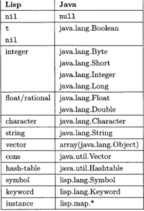
Section 6: Distributed Object Management The archive server shares resources with clients using a remote object invocation service. It provides clients Lisp-to-Java translations of CLOS instances using the Java Object Serialization Specification. Programs may assert explicit control over the scope of data migration, allowing both servers and clients to optimize performance with caching and prefetch operations.
Client
User browses source code, reads
annotations, creates new versions
of definitions, and is notified of
issues requiring attention.
2
Design Artifacts
2.1
Artifacts Defined
The term design artifact is applied here rather broadly to denote all the information generated
by a collaborative engineering effort. This includes not only traditional artifacts such as design
diagrams and documentation, but observations, assertions, and design rationale that are seldom
tracked effectively in contemporary engineering support environments. We should capitalize on
the popularity of electronic communication (such as electronic mail) for collaborative discourse by
maximizing its value to future design maintenance or reengineering efforts. While many such design
artifacts are commonly stored (e.g. email archives), we need to explicitly represent the relationships
between these resources as design artifacts in their own right. Simply capturing the link between
an engineer's comment and the version of the design it describes adds a great deal of relevance to
future users. The concept of design artifacts is applied to cases such as these, where the strategic
application of existing design and communication technologies can be used to support more efficient,
productive engineering teams.
2.2
Evolution of Designs
Some design artifacts, such as specifications, source code, and documentation tend to evolve as a
sequence of discrete revisions. In a collaborative setting, these revisions often occur in response to
observations, suggestions, or discussions by the members of an engineering team. While the change
history of an artifact can be captured by version control systems with relative ease, the rationale
leading to such changes, even if captured electronically, may be difficult to retrieve. A key observation
is that an engineer may express the most valuable rationale once a design revision has already been
completed. Explanations and clarifications occur frequently as part of normal collaborative discourse,
and should be managed as valuable project assets. Evolving an existing system requires engineers
to recreate the environment of design goals and trade-offs that led to a previous implementation.
Artifacts supporting design evolution, whenever they are created, contribute to a design genealogy,
outlining key points and issues that should not be neglected when later adapting a system.
3
Archive Framework
DATE archives represent a set of design artifacts and track their evolution as designs
develop and adapt. Project resources and the relationships between them constitute
nodes and links in a project web, which applications operate over in support of specific
engineering tasks.
" Representations target design evolution and tool integration.
DATE represents design artifacts at an intermediate level, establishing a level
of granularity which applies across engineering support tools while providing a
logical platform for building more powerful knowledge representations. Archives
track the evolution of software engineering artifacts such as source code
defini-tions and documentation.
* Strategic application of domain analysis.
Archives integrate flexible graph constructs with uniform data structures
de-rived from domain analysis.
A source code representation based on
func-tional decomposition, configuration management, and version tracking supplies
a framework for software engineering archives.
3.1
Design Goals
The primary design goal of the DATE system is to facilitate powerful engineering support
appli-cations by managing the design artifacts related to a project. Such artifacts, or resources, include
design rationale and diagrams, discourse between engineers, and in the case of software engineering,
all the components of the product itself. We wish to cast the problem of system maintenance and
adaptation as one of incrementally evolving original designs and design goals. To this end, we must
maximize the value of design artifacts to future users, allowing engineers to adapt a system based
on direct knowledge of previous design decisions and trade-offs. We wish to support a model of
incremental adaptation, rather than one based solely on major milestones or system releases. In
particular, care should be taken to preserve the minor changes that culminated in a release. Archives
should continuously represent consistent project states, where consistency applies not to overall
sys-tem function, but to the integrity of individual resources and their relations. Users may still make inconsistent engineering changes, but we wish to support the timely discovery of such errors. Mini-mally, the DATE system should capture when and how modifications are made. At best, the system would support the automatic detection and containment of engineering conflicts.
Even a project involving only a handful of participants is expected to generate a large body of design artifacts. Re-engineering an existing system can become difficult or impossible when original decisions and rationale must be inferred due to lack of artifact acquisition or indexing. Engineers must assume the role of software archaeologists, searching for artifacts and theorizing as to their relationship to the task at hand. The convenience and availability of computers as a tool for design and discourse greatly ameliorates the resource acquisition problem, but there is little infrastructure available for archiving such resources in a useful manner. It is commonplace to produce electronic specifications and documentation, or to discuss an evolving design over electronic mail. These design artifacts are easily stored, but the relationships, or links, between resources are often ephemeral. It is these links, acting as persistent, bidirectional pointers, that give structure to an archive.
Resources and links combine to form a web of information concerning a collaborative project. We are especially interested in links that promote resource discovery in the course of normal engineering tasks (e.g. editing a source code definition). One important step in building useful archives is to capture links that, while immediately available at design time, tend to be lost as a system develops.
A software engineering archive, for example, should link documentation or bug reports to the specific
regions of source code they describe. Such program annotations are easily generated and stored, but offer a future developer little value unless linked to a particular state of the system's evolution.
A key trade-off in designing such a knowledge-based system is balancing domain analysis with
archive flexibility. While we wish to minimize the amount of engineering methodology we impose on system users, domain analysis can be used to increase efficiency in representing and retrieving resources. In theory, we can represent any data structure as simple resources (nodes in a graph) and links, with a minimal number of link types. Links can accept other links as their predicates, further specifying a particular relationship. One powerful application of domain analysis is in defining a vocabulary of link types. This idea not only provides a more compact representation for links, it constrains the expression of engineering discourse such that automated, constraint-guided traversals of archives are more tractable. For example, links implying questions, agreement, disagreement, and alternatives are appropriate for a broad array of decision-making processes [7].
of nearly any type of electronic data, certain regions of archive web will have inherently uniform
structure. These cases can be isolated by domain, then represented and navigated much more
efficiently. This type of domain knowledge can often be encoded without at all constraining a
project's engineering methodology. Certain types of source code and documentation, for example,
must rigidly conform to a predefined structure.
3.2
Resources
For the software engineering application of the DATE system, the domain analysis discussed above
resulted in a data structure for representing source code. Since a software project naturally focuses on
the program or programs being developed, this provides a consistent framework for all the project's
associated design artifacts. Traditional artifacts such as design specifications, documentation, test
cases, and bug reports branch off from the specific regions of source code they relate to. While a great
deal of resource structure may be derived from source code stored in normal files, we wish to maintain
a uniform representation that may be conveniently utilized by new applications. The following
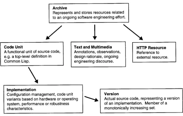
subsections outline key properties of the DATE source code representation, which is illustrated in
Figure 2.
3.2.1
Granularity: Code Units
The representation should decompose source code into the smallest logical blocks that do not require
deep understanding of programming language semantics. Here, we will define these blocks as code
units. The selected decomposition should apply across various implementations and revisions of
the programming language used. Note that while the DATE framework provides an appropriate
platform for systems such as integrated development environments, detailed language semantics are
not considered part of the core system. For many languages, the function definition is a natural
example of an appropriate code unit.
3.2.2
Configuration Management: Implementations
The core source code representation should account for different implementations of the functionality
delivered by a code unit. These implementations may apply to different hardware or software
configurations, or to different engineering trade-offs. For example, it may be appropriate to maintain
Archive
Represents and stores resources related to an ongoing software engineering effort.
Code Unit Text and Multimedia HTTP Resource
A functional unit of source code, Annotations, observations, Reference to e.g. a top-level definition in design rationale, ongoing external resource.
Common Lisp. engineering discourse.
Implementation
Configuration management, code unit Version
variants based on hardware or operating Actual source code, representing a version system, performance or robustness of an implementation. Member of a
characteristics. monotonically increasing set.
Figure 2: Code archive resource structure. Arrows represent a one-to-many relationship.
one implementation of a function that is highly optimized, while another captures debugging and metering information.
3.2.3 Representing Time: Versions
In order to maintain a coherent project history, the decomposition of source code functionality should be matched by an equally fine-grained representation of time. When an engineer links an annotation to a particular version of a source code definition, that link should not generally be broken. As changes are made, versions of an implementation are created as part of a monotonically increasing set. This feature is similar to the version control on files offered by many commercial source code management systems.
3.3
Application to Programming Languages
While the source code representation described in Section 3.2 may be applied to many programming languages, we selected Common Lisp for the demonstration system. The primary reason for this choice is the fine-grained abstractions allowed by the Common Lisp Object System (CLOS). Hinging on generic functions rather than data structures, CLOS allows methods to dispatch on a number
of classes, isolating common functionality as a first-class entity. In this case, code units are defined
as top-level Lisp forms. These include definitions for generic functions, methods, classes, macros,
and global variables. Implementations can vary by conventional Lisp compiler directives, or by the
more qualitative, behavior-based aspects mentioned above. The Dylan programming language offers
potential for fine-grained code unit manipulation similar to that of Common Lisp.
For more data-oriented languages such as Java and C++, we would decompose classes into their
methods and instance variables. This is very useful for documentation and annotation purposes,
but the prospects for fine-grained code unit reuse and automatic recomposition are weaker than in
the CLOS model.
3.4
Links
While the source code representation described in Section 3.2 provides archives with a functional
structure, it is the links between resources that drive collaborative engineering applications. Several
categories of links are immediately applicable to the software engineering domain.
3.4.1
Language Semantics
These links encode relationships implicit in a system's source code, many of which are commonly
utilized in software development environments. For example, such links connect methods to their
generic functions, or function and variable references to their code units. The ability to create these
links depends upon the level of support for programming language semantics. Some link types are
easily derived, while others require a great deal of complexity (e.g. those depending on Common
Lisp macro expansion).
3.4.2
Documentation and Specification
We assert that program-level specifications and documentation are much more valuable when
per-sistently linked to the source code they are meant to describe. These important project components
are traditionally encoded along with source code either as comments, or as part of a definition (as
in Common Lisp documentation strings). Reifying specifications and documentation as archive
re-sources means that they may be reasoned about and operated over at the same level as source code.
Specifications can be associated with proofs or test cases, and users can make assertions about the
validity of documentation. The problem of maintaining synchronization between source code and
documentation still persists, but is now contained in a rational manner. Documentation can be
at-tached to any of the three code representation levels described in Section 3.2. Archives would serve
as an excellent platform for a system which attempts to roll version-specific annotations forward as
a definition is modified.
3.4.3
Annotation
Annotation is a rather broad term, used here to denote a link associating a resource with relevant
information. The documentation and specification links described in Section 3.4.2 may be considered
specific classes of annotation links. We are especially concerned, however, with the sort of loosely
structured annotations, or programmer comments, often hampered by linear text editing technology.
By separating the encoding of comments from that of source code, we remove restrictions on comment
length, quantity, and media type which are inherent in their common representation. With the
archive model in place, annotations are no longer restricted to plain text, taking the form of HTML,
images, even audio and video.
Extensive comments have a way of hindering programmers who are familiar with a system, and
of overwhelming novices. Maintaining comments as a separate, but closely linked counterpart to
source code facilitates multiple program views, based on manual or machine-assisted selection of
annotations. We also note the ability to maintain multiple annotation links to a single resource, as
in a comment which applies to multiple regions of source code. The annotation not only describes
the functional aspect that a region of code is part of, it acts as a navigational bridge to other, related
components.
The ability to annotate previous annotations provides opportunities for collaborative discourse.
The discussion threads common in mailing lists form within archives, with annotation trees branching
off from the source code, documentation, or other resource that initiated the discourse. Electronic
mail still plays an important role, but one of archive change notification rather than acting as the
primary representation for design rationale. Traditional bug tracking email would take the form of
notifications to those responsible for maintaining a resource. As discussed in Section 3.1, subclasses
of annotation links are used to enforce particular models of discourse in discussion threads. This
idea is especially useful for supporting the automatic traversal and characterization of annotation
graphs.
3.4.4
Testing and Verification
The archive structure provides an excellent opportunity to closely integrate testing and verification
information with source code, without sacrificing programmer convenience or program efficiency. A
primary goal is to capture the ad-hoc test cases used by most programmers, but often discarded
due to lack of a convenient archiving method. More formal, robust test sets may add value by
facilitating automated regression testing. Test cases, depending on their scope and the state of
program development, may be run whenever code units are modified. Adding fine-grained test
cases (covering only one or a few code units) provides engineers with a convenient way to protect
their assumptions against shifting abstractions or misinterpretation by future developers. Particular
implementations of code units may be tested for overall performance, algorithm behavior, or even
checked for consistency with a programmer-supplied proof.
3.5
Collections
While we assert that linear text is inadequate for representing source code and its associated design
artifacts, files play an important organizational role in contemporary development environments.
Editing a number of related functions in an Emacs [21] style buffer still offers a great deal of value,
though we wish to add interface features for supporting archive navigation. Files are replaced by the
concept of collections: linear, possibly overlapping sets of source code resources. Such collections may
refer to specific versions or to code units in general, with a mechanism for automatically selecting
which implementation and version to view. As with the selection of our source code representation,
this concept is applicable to many programming languages. Collections yield their full advantage,
however, when applied to languages built around fine-grained abstractions. Editing all the methods
of a Common Lisp generic function, for example, may pull together code units from all over a large
system.
We wish to accommodate the class-based, data-oriented source code view of Java and C++,
as well as views based on one or more aspects of functionality. Both models are useful, and the
programmer should not be forced to choose between them when storing implementations. Collections
accommodate both constraint-based, dynamic views of source code, and manually assembled groups
of resources meant to illustrate a particular idea. Collections may represent the current focus of an
individual developer, or provide tutorials for new users. They may correspond to varying levels of
abstraction, appropriate for tasks ranging from system orientation to low-level debugging.
3.6
Resource Indexing
While saved collections of resources provide an excellent basis for organizing and working with source
code, we still require the ability to efficiently search an archive. Appropriate search constraints vary
by archived data type, and by programming language for software engineering. It is not necessary
that an archive efficiently map all artifacts, but almost all archives will need the ability to index some
of their resources for quick retrieval later. Examples might include natural language queries based on
documentation, or retrieval of function definitions by argument pattern. The demonstration archive
performs indexing for code units (corresponding to Common Lisp definitions) based on their Lisp
names. While top-level Lisp forms are not required to have unique names, definitions including those
for functions, classes, and variables do. Apart from the normal archive web structure, we maintain
lookup tables which allow the rapid retrieval of code units by name, package, and definition type.
4
User Interface
The user interface demonstrates several software engineering support features made
possible by the DATE archive.
" Dynamic source code views.
Files are replaced by logical groups of source code definitions, dynamically
con-figurable to the task at hand.
" Rationale capture by annotation.
Operating over a fine-grained source code representation adds new value to
informal comments and discussions related to specific code.
" Integration of tools.
Integration of tools for managing source code, documentation, and collaborative
discourse promotes resource discovery and consistency.
4.1
Design Goals
The goal in designing the demonstration interface was not to implement a full-featured integrated
development environment (IDE) or knowledge navigator. Rather, we wish to illustrate a set of
soft-ware engineering support facilities which are implemented with relative ease when able to leverage
the DATE archive framework. Accordingly, the demonstration screens shown are designed for
intel-ligibility rather than compactness. The interface takes the form of a network client, supporting a
great deal of local interaction, but closely tied to a remote project archive. The following subsections
outline several features that the client interface was designed to demonstrate.
4.1.1
Fine-Grained Configuration Management
The configuration management provided by code unit implementations allows developers to compose
coherent, task-oriented views from a large, heterogeneous base of source code. Most conventional
source code representations force developers to make an unfortunate choice:
Design Artifact Tracking
and Evolution
MIT
Artificial
Intelligence Lab
Figure 3: Client splash screen.
2. Accumulate multiple implementations in cluttered, highly conditionalized files.
With support for multiple, overlapping views, the developer may conveniently edit a buffer containing
exactly the set of relevant definitions, regardless of selected configurations.
4.1.2
Multidimensional Source Code
The archive framework facilitates the development of multiple code views at two levels. First, the
archive's decomposition of source code by functionality and time provides a rich space of resources.
The demonstration interface allows users to view slices through this resource space, the collections
discussed in Section 3.5. The configuration management discussed above is a specialized application
of this idea. The archive framework is also appropriate for supporting lower-level multidimensional
views of source code definitions. For example, a developer may wish to filter out type checking,
debugging, or performance metering code from the current view. This recognizes the idea that a
single definition in a contemporary programming language often corresponds to several semantic
threads. The demonstation interface implements the first, higher level of multidimensional code
support and provides a platform for developing the latter.
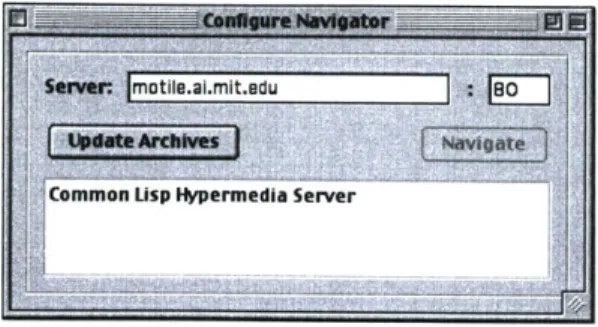
Figure 4: Client configuration window.
4.1.3
Integration of Tools
The archive representation provides a logical base for integrating source code development with tools
for documentation, bug tracking, discourse, and project management. The demonstration interface
utilizes the basic archive framework to support engineering discourse based on source code. When
a user edits a source code definition, related design discussions, observations, and problems are
immediately available for inspection.
4.2
Interface Components
The DATE demonstration interface is implemented as a Java application, communicating with
archive servers via HTTP. Section 11.7 lists the source code for this application. The following
subsections outline the main interface components.
4.2.1
Configuration
The client software first presents the user with a configuration window as shown in Figure 4. The
user identifies the archive server of interest, selects Update Archives, and is presented with a list
of available projects. The example in Figure 4 list only one archive, containing design artifacts for
a web server written in Common Lisp. The user chooses the desired archive and selects Navigate
to create an archive navigator window.
4.2.2
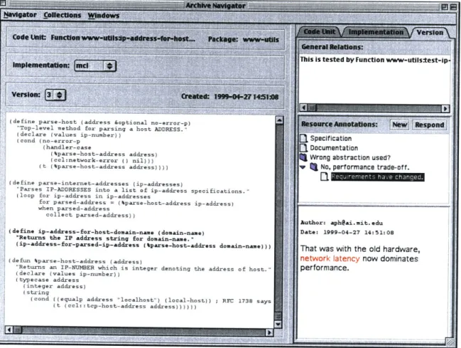
Archive Navigator
An archive navigator window, as shown in Figure 5, allows users to navigate, edit and create source
code along with its associated design artifacts. The core feature of a navigator window is the editor
~ieaimit.du
f307(define parse-host (address &optional no-error-p) 'Top-level method for parsing a host ADDRESS." (declare (values ip-number))
(cond (no-error-p (handler-case
(4parse-host-address address)
(ccl:network-error () nil))) (t (4parse-host-address address))))
(define parse-internet-addresses (ip-addresses)
"Parses IP-ADDRESSES into a list of ip-address specificatior (loop for ip-address in ip-addresses
for parsed-address = (%parse-host-address ip-address) when parsed-address
collect parsed-address))
(define ip-address-for-host-domain-name (domain-name) "Returns the IP address string for domain-name."
(ip-address-for-parsed-ip-address (parse-host-address domai
(defun %parse-host-address (address)
"Returns an IP-NUMBER which is integer denoting the address (declare (values ip-number))
(typecase address (integer address) (string
(cond ((equalp address "localhost") (local-host)) ; RSC (t (ccl:: top-host-address address) )))))
in-name)))
Figure 5: Archive navigator window.
Source Code Version
(defun compute-value (a b c)
(let ((z (sqrt (+ a b))))
1a
-HTML Text
Observation Link You can save several
Author: [email protected] multiplications if you...
Summary: This could be faster.
HTML Text
Response Link Your method overlooks
Author: [email protected] an important case...
Summary: No, introduces a bug.
(a)
(b)
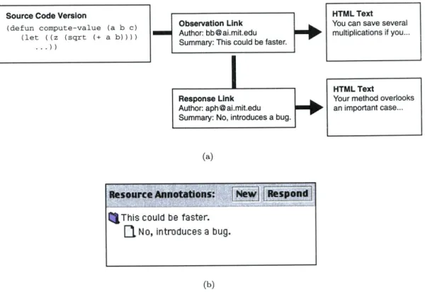
Figure 6: (a) Archive and (b) interface representations of a discussion thread.
buffer, which displays versions of several code units simultaneously. The version currently being
edited is considered the selected resource, and the rest of the window is dedicated to describing the
local archive web. The resource information area directly above the editor buffer details the selected
resource's code unit, implementation, and version. The user may select alternate implementations
or versions, with such selections reflected in the editor buffer. The right-hand column displays links
specific to one of the three code representation levels, as selected by the Code Unit, Implementation,
and Version tabs. This allows, for example, a distinct separation of assertions on top-level code
units from discussions concerning a particular implementation.
While all resource links may be rendered as English sentences, it is useful for the interface to
provide special handling for selected link types. In the case of the demonstration system, annotation
links are filtered out and displayed in the lower part of the link area. The client also searches for
responses, represented in the archive as annotation links to other links of the same type (see Figure
6). In this manner, the interface presents a discussion tree, a simple example of which is shown in
Figure 5. Selecting an annotation link from the tree displays the target resource in the lower-right
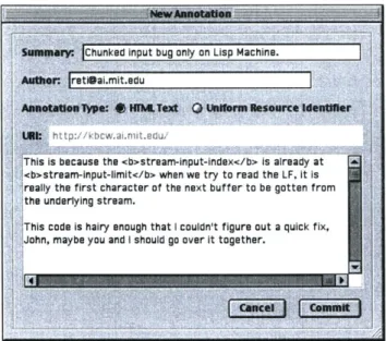
Figure 7: Annotation editor window.
area of the window, which provides display capabilities similar to those of a web browser. Other
links, both from and to the selected resource, are displayed as sentences in the General Relations
area. When such a link has a source code resource as its other predicate, selecting it appends that
resource to the editor buffer.
4.2.3
Annotation Editor
Selecting New or Respond from the Resource Annotations area of the archive navigator displays
the window shown in Figure 7. The annotation editor allows the user to specify a new annotation's
summary, description, and author, and to create a new HTML text resource or external HTTP
reference. If the editor was displayed by selecting New, the annotation link associates the selected
source code resource with the new modifier resource. If Respond was selected, the HTML text or
URI is associated with the currently selected link in the annotation tree. While the demonstration
system only supports the creation of generic annotation links, the editor window is an appropriate
interface for further quantifying engineering discourse. Users could select annotation link types such
as bug report, improvement, agreement, disagreement, or alternative.
24
Senegar- Chunked input bug only on Lisp Machine.
AMOWer: [email protected]
AssAU"T "*w~s: HM
u
.Text0 U D u Ne asUrce identnerSht tp:// kbcw.al mit edu,
This is because the <b>stream-input-index</b> is already at <b>stream-input-limit</b> when we try to read the LF. it is
,really the first character of the next buffer to be gotten from the underlying stream.
!This code is hairy enough that I couldn't figure out a quick fix,< John, maybe you and I should go over it together.
4.3
Editing Source Code
The demonstration client is built around a dynamic editor buffer, where source code is browsed and
manipulated. While the example buffer shown in Figure 5 gives the impression of editing a source
code file, it actually pulls together resources from a broad base of archived data. This is the logical
approach for displaying the collections of source code discussed in Section 3.5. Users may start with
saved collections of resources, then add and remove elements as they require additional information
or shift focus. Several development environments for the Dylan programming language currently
implement this kind of dynamic buffer functionality.
The navigator offers basic hypercode support (implemented as the meta-dot gesture familiar to
Lisp programmers), adding requested code units to the dynamic buffer. For uniform, relatively
compact resources such as source code definitions, this model of hypercode is more appropriate than
the web browser style of 'jumping" to a new resource. Rather than executing a one-dimensional
walk of the archive's resource space, users vary the size of their working set, exploring the archive
on many fronts. The currently selected resource is determined by the position of the insertion caret,
and therefore may be changed using the mouse or arrow keys. In the example navigator window,
the selected source code version (represented by its Lisp definition in the buffer) is colored black
while all others are grey. While the demonstration system does not support saving new versions of
definitions, it provides standard text editing features. We constrain normal editing such that the
user may not select text which spans multiple definitions.
5
Persistent Object Support
Since the DATE system has at its core an archive of resources and links, efficient
management of persistent storage is a crucial enabling technology. The design of the
persistent object support layer focuses on a few key concepts:
" Integration of storage mechanisms.
Objects are automatically distributed across appropriate storage mechanisms,
which may include databases, file systems, or the web.
" Persistent object identifiers.
Identifiers encapsulate references to remotely stored instances, acting as
place-holders in partially loaded data structures.
* CLOS programming style.
The transaction and class specification models are tailored to the Common Lisp
Object System (CLOS) programming style. Slot accessors load stored instances
transparently, and objects may be saved using method combination.
While this section presents persistent object technology for supporting Common Lisp, the key issues
discussed apply across programming paradigms. Defining a generalized object persistence API
both reduces source code complexity and insulates the compile-time system from volatile storage
configuration issues. Such an interface must allow us to add support for emerging storage technolgies
and to adjust storage mechanism selection criteria without any modifications to the core system.
5.1
Design Goals
5.1.1
Integration of Storage Mechanisms
We wish to insulate the archive system from direct database access, both to ease the transition
to new storage methods and to provide a programming environment where persistence is mostly
transparent. The ability to operate seamlessly over a heterogeneous group of storage mechanisms
allows the archive to act efficiently as a clearinghouse for all the resource types related to a project.
Storage mechanisms might include databases, local or distributed file systems, and the World Wide
Web, each offering performance characteristics appropriate for certain classes of data. One storage
mechanism, for example, may be well suited to access patterns on source code while another is better
equipped to store video.
5.1.2
Bounding Interaction
We require a persistent object layer that is well-suited to navigating a tangled web of objects, while
remaining mostly transparent to the archive. We would like to be able to instantiate an object and
operate on it normally without necessarily accessing the persistent state of all the objects bound
to its slots. In this manner, well-contained archive traversals require a relatively small amount of
interaction with storage mechanisms, and therefore less access to shared network resources. We
assume that the most frequent archive operations will involve read-only walks of the archive web
(e.g. browsing annotations, searching for source code), suggesting excellent prospects for object
caching and prefetching.
5.1.3
Programming Interface
With the design constraints above in mind, there remains a great deal of flexibility in choosing the
persistent object layer's programming interface. The two primary issues involved are choosing a
type system and handling atomic modifications to the persistent state. The former is especially
problematic for Common Lisp, since CLOS does not typically enforce constraints on slot types.
This complicates, for example, mapping CLOS classes to a database schema which rigidly enforces
field types. We initially experimented with imposing type specification on class slots, but eventually
decided that this added too much of a burden for the programmer. In general, storage mechanisms
are responsible for handling the loose typing traditionally supported in Lisp programming. Some
storage mechanisms may require that the CLOS :type slot option is always used in the classes it
stores in order to ease database schema mappings.
Supporting atomic changes to an object's (or to objects') persistent state is more a question of
programming style. Two reasonable alternatives are to wrap object changes within a transaction
macro (similar to with-open-f ile), or to explicitly save (snapshot) objects via a method call
whenever appropriate. We chose the latter method primarily because it has less of a stylistic impact
on the system's source code. Object saves may be hidden within CLOS : af ter methods, and easily
conditionalized. Any changes made to an object's slots are considered to be cached modifications.
Saving one or a group of objects commits these modifications to the persistent state.
5.2
Storage Mechanisms
Storage mechanisms manage communication between the persistent object support interface and the
actual modes of storage supported on the system. Slot access management and the assignment of
persistent identifiers are handled in a centralized manner, so storage mechanism implementations
tend to be quite compact. The demonstration system uses a portable log-based storage mechanism
which utilizes the local file system. Section 11.3.7 lists the source code for this implementation,
and Section 11.6.9 shows an example configuration. Earlier during system development, we used a
platform-specific storage mechanism which translated to Statice, an object-oriented database for the
Symbolics Lisp Machine (Section 11.3.16). The following subsections document the programming
interface for allocating and manipulating storage mechanisms.
5.2.1
allocate- storage-mechanism
allocate-storage-mechanism name class-name &key &allow-other-keys
Generic Function
Allocate an instance of a storage mechanism, keyword options vary according to class-name.
name
A unique symbol name to identify the instance.
class-name
Name of a subclass of storage-mechanism.
5.2.2
optimize-storage-mechanism
opt imize-storage-mechanism &key storage-mechanism verbose
Function
Calling this function allows a storage mechanism to perform computationally intensive time or space
optimizations. Examples might include database compaction or file system defragmentation.
storage-mechanism
Storage mechanism to be optimized, defaults to
*default-storage-mechanism*.
verbose
When non-nil, the storage mechanism may print status information
to *standard-output*.
5.2.3
*default- storage-mechanism*
*def
ault-storage-mechanism*
Parameter
5.2.4 *supported-storage-.mechanisms*
*supported-storage-mechanisms* Parameter
A list of all the storage mechanisms currently in use.
5.3
Identifiers
An identifier contains all the information necessary to retrieve a persistent object. Identifiers con-sist of storage mechanism information, a unique serial number, and CLOS class information. An interesting property of identifiers concerns the class information, which enables an identifier to in-stantiate itself without accessing any persistent state. A skeleton instance, one with none of its slots filled, is created when an object is first referenced. Slot values are not fetched until the application first accesses persistent data. In this manner, an identifier may stand in for blind slot modifications (those not requiring other slot values) and allow those new values to be read or saved without read-ing any persistent state. Similarly, skeleton instances can be used for method dispatch before their persistent state has actually been retrieved.
An identifier is assigned to a persistent object the first time it is saved, and is associated with it throughout the object life-cycle. References to other persistent objects in the slots of that object are stored using their identifiers as proxies. The representations of an object across system restarts do not satisfy Lisp pointer equality (Lisp eq), but do represent equivalent application entities (Lisp eql). If two separate program threads request an object for the same identifier, they receive references to the same CLOS object. Therefore, as with normal CLOS objects, locking must be maintained at the application (in this case, archive) level.
5.4
Persistent Classes
The initial version of the persistent object layer utilized the Metaobject Protocol [14], using a metaclass to make the definition and use of persistent classes almost completely transparent. This approach proved not to be portable across Common Lisp implementations, so we moved to a variant of the def class macro. This implementation constraint requires that persistent object slots are read and modified exclusively by their slot accessors, rather than slot-value or with-slots. The following subsections document the basic interface for defining and using persistent classes. The source code implementing this interface is listed in Section 11.3.12.