Publisher’s version / Version de l'éditeur:
Construction Technology Update, 2010-08-01
READ THESE TERMS AND CONDITIONS CAREFULLY BEFORE USING THIS WEBSITE. https://nrc-publications.canada.ca/eng/copyright
Vous avez des questions? Nous pouvons vous aider. Pour communiquer directement avec un auteur, consultez la première page de la revue dans laquelle son article a été publié afin de trouver ses coordonnées. Si vous n’arrivez pas à les repérer, communiquez avec nous à PublicationsArchive-ArchivesPublications@nrc-cnrc.gc.ca.
Questions? Contact the NRC Publications Archive team at
PublicationsArchive-ArchivesPublications@nrc-cnrc.gc.ca. If you wish to email the authors directly, please see the first page of the publication for their contact information.
NRC Publications Archive
Archives des publications du CNRC
Access and use of this website and the material on it are subject to the Terms and Conditions set forth at
Fire performance of fibre-reinforced polymer systems used for the
repair of concrete buildings
Bénichou, N.
https://publications-cnrc.canada.ca/fra/droits
L’accès à ce site Web et l’utilisation de son contenu sont assujettis aux conditions présentées dans le site LISEZ CES CONDITIONS ATTENTIVEMENT AVANT D’UTILISER CE SITE WEB.
NRC Publications Record / Notice d'Archives des publications de CNRC:
https://nrc-publications.canada.ca/eng/view/object/?id=637ce48b-9891-4025-b51f-e285980f41f9 https://publications-cnrc.canada.ca/fra/voir/objet/?id=637ce48b-9891-4025-b51f-e285980f41f9The use of fibre-reinforced polymers (FRPs) has become an accepted repair methods for concrete bridge structures. Their use for repairing concrete buildings and parking garages, however, has been limited because of concerns about their behaviour in fire. NRC-IRC performed full-scale fire tests on FRP-strengthened circular columns, T-beams, and slabs to shed more light on their fire performance.
Properties of FRPs
A fibre-reinforced polymer is a two-component material consisting of high-strength fibres embedded in a polymer matrix. FRPs offer great advantages for the repair of concrete structures because of their high strength, corrosion resistance, and ease of application. They have been successfully used both internally, as an alternative to steel reinforcement, and externally for strengthening damaged concrete.
The three main types of FRP fibres used in most structural applications are carbon, glass, and to a lesser extent, aramid. Each has advantages and disadvantages. Carbon fibres are favoured for flexural strengthening because of their high stiffness, strength, and superior fatigue and durability characteristics. Glass fibres are more commonly used for shear strengthening.
The polymer matrix supports and protects the fibres, transfers and distributes forces to the fibres, and disperses and maintains the spacing of the fibres. The polymers used in structural applications need to have good thermal stability, chemical resistance and low creep. In fire situations, the matrix is the vulnerable component of FRPs because of its combustibility and softening with rising temperatures.
FRP behaviour in fire
One of the characteristics of FRPs is their low glass transition temperature (Tg). Tgis
the midpoint of the range of temperatures over which the FRP polymer matrix
undergoes a change from hard and brittle to viscous and rubbery. Polymer matrices that cure at room temperature and are often used for strengthening concrete structures have glass transition temperatures ranging from 60°C to 100°C. Without protection from heat, a polymer matrix may also ignite, emit smoke, and support flame spread. One of the main objectives of the NRC-IRC research was to investigate how low FRP glass transition temperature affected the performance of insulated FRP concrete strengthening systems in fire situations.
by N. Benichou, V.K.R. Kodur, M.F. Green, and L.A. Bisby
This Update reviews NRC-IRC research on the fire resistance of externally
bonded, fibre-reinforced polymer (FRPs) systems used for repairing concrete
building members. The research showed that FRP systems that include
specially designed insulation can enable repaired or strengthened concrete
members to exceed the 4-hour fire resistance requirements of building codes.
Construction Technology Update
No. 74
Fire Performance of Fibre-Reinforced
Polymer Systems Used for the
2
When exposed to fire, FRP materials may suffer charring, melting, delamination, cracking and deformation. Figure 1 shows that for some types of matrices, debonding can be well advanced at 200°C. It also shows that the fibres themselves lose strength with rising temperatures, with carbon fibre losing the least.
Fire resistance experiments
The objective of the NRC-IRC experiments was to investigate the fire and structural performance of insulated FRP-strengthened columns, T-beams and slabs. The FRP systems tested used proprietary insulations that were spray-applied.
FRP-wrapped circular columns
Full-scale fire tests were carried out on four FRP-wrapped circular concrete columns (400 mm ø x 3810 mm long) under full sustained service loads. Figure 2 shows a column at various stages in the testing process. 0 20 40 60 80 100 120 0 100 200 300 400 500 600 % of R oom T e m p er at ur e St rengt h Temperature (°C) Average Bond Strength
Carbon FRP Strength
Aramid FRP Strength
Glass FRP Strength
Figure 1.Change in FRP strength and bond strength with temperature increase [References 1 and 2]
(The curves are not definitive, and should not be used for design purposes.)
Figure 2.Preparation and testing of circular concrete column Bare reinforced
concrete column
Column with FRP installed
Column with FRP wrap and spray-on insulation in test chamber
Column after fire resistance testing
Table 1.Results for column fire tests
Fire Predicted Type of insulation Test load resistance strength (at room Column No. Type of FRP and thickness ratio1 (min) temperature) (kN)
1 1 layer Gypsum-based, 0.50 > 3002 5,094 Carbon Tg= 93°C 57 mm 2 1 layer Gypsum-based, 0.50 > 3002 5,094 Carbon Tg= 93°C 32 mm 3 2 layers Cementitious, 0.56 > 3002 4,720 Carbon Tg= 71°C 53 mm 4 2 layers None 0.56 210 4,720 Carbon Tg= 71°C
1. Test load ratio is the ratio of the applied load during fire tests divided by the predicted strength (at room temperature). 2. After the insulated columns had passed 300 minutes (5 hours) of fire resistance, the load was increased to induce failure.
All four columns were internally reinforced with conventional steel reinforcing bars and spirals as per ACI design specifications. The FRP wraps were applied around the circumference of the columns to provide confinement. Three of the columns had fire insulation spray applied to the FRP wraps and one was tested without any insulation. Test results are shown in Table 1.
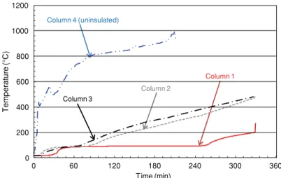
Figure 3 plots temperatures recorded at the FRP–concrete interfaces of each column. It shows that the insulation provided good thermal protection for the three columns even though the Tg(Table 1) was exceeded
early in the fire.
Even after prolonged fire exposure, the insulation remained in place and in good condition so that the FRP system – consisting of the insulation and the FRP layer – provided
significant protection for the concrete. The FRP systems allowed the columns to achieve satisfactory ULC S101 fire resistance ratings [Reference 3] – in excess of 5 hours – even when the Tgof the FRPs was exceeded early.
The uninsulated, FRP-wrapped column sustained its applied load for about 3.5 hours, falling short of the 4-hour (240-minute) fire-resistance requirement. In this case, the FRP wrap debonded from the column in less than 30 minutes and was eventually consumed by the fire.
The results showed that FRPs, bonded to repaired concrete surfaces and protected by insulation, can contribute to the overall fire resistance of concrete members even though the FRP itself might be sacrificed during a fire. This increases the likelihood that after a fire concrete members could be repaired by reapplication of FRP systems rather than replaced. It also means that exceeding the glass transition temperature (Tg) does not cause the insulated FRP system
to lose its effectiveness.
FRP-strengthened T-beams
Full-scale fire tests were conducted on reinforced concrete T-beams (1220 mm wide x 3900 mm long) that were strengthened in flexure with one layer of carbon FRP sheets bonded to their undersides and around the webs (Figure 4).
All four T-beams were protected by insulation around the web portion of the beams. They were tested under full applied load according to the ULC S101 standard.
All the beams achieved fire resistance ratings of 4 hours (Table 2). In fact, they were able to sustain the applied loads for more than four hours. The results of tests conducted after the T-beams had cooled to room temperature indicate that the capacity of the members after the fire tests was equivalent to the capacity of the unstrengthened members before the tests. Thus, provided that reasonable FRP-strengthening limits are not exceeded as suggested by ACI 440.2R-08 [Reference 4], these members could, after careful inspection, be considered undamaged by fire and be rewrapped with FRP and insulation for continued service. 0 200 400 600 800 1000 1200 0 60 120 180 240 300 360 T e m p e ra tu re (°C) Time (min) Column 4 (uninsulated) Column 3 Column 2 Column 1
Figure 3.Temperature change with time at the FRP/concrete interface for the column tests
All bars10mm Ø Spaced at 150mm o/c longitudinally 20mmØ bars Insulation FRP System bs = 1220 mm hs = 150 mm h = 400 mm bw = 300 mm
Beams 3 & 4 Beams 1 & 2
10 mm bars
610 610
FRP-strengthened slabs
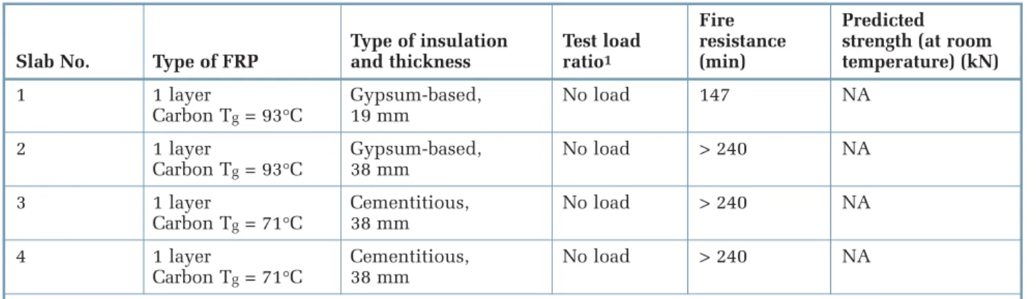
Intermediate-scale fire resistance experiments were conducted on four reinforced concrete slabs (150 mm thick x 950 mm wide x 1330 mm long) strengthened with carbon FRP sheets bonded to their undersides. The slabs were internally reinforced with conventional reinforcing steel, and were constructed using carbonate aggregate concrete. The four slabs were insulated with spray-applied cementitous or gypsum-based plasters, proprietary products developed specifically for this application. The slabs were fire tested according to ULC S101 [Reference 3] (equivalent to ASTM E119 [Reference 5]).
The tests provided insight into the appropriate insulation configurations and thicknesses to be used for full-scale testing of FRP-strengthened beams and columns. The tests demonstrated that a 4-h fire resistance rating could be achieved by affixing as little as 38 mm of supplemental insulation to the FRP wrap (Table 3). A 19-mm thickness of insulation could
provide a 2-h fire resistance rating for slabs carrying only their self-weight.
In all cases the insulation provided good thermal protection to the FRP sheets, although the Tgwas exceeded in less than
2 hours in all four cases. Again, this demonstrates that exceeding the Tgis not
an appropriate failure criterion for FRP-strengthened concrete members.
Applying fire research findings
Because FRP materials are combustible, they require some form of fire protection to restrict the evolution of smoke and the spread of flame. The specific requirements depend on the classification of the building and the properties of the FRP system being used. Most FRP manufacturers have coatings or other fire protection systems to meet smoke and flame spread requirements.
For structural performance in fire, the research has shown that externally bonded FRPs can be protected with insulation to give fire resistance ratings in excess of 4 hours. Thus, FRP materials can be used for
4
Table 2.Results for T-beam fire tests
Fire Predicted Type of insulation Test load resistance strength (at room T-beam No. Type of FRP and thickness ratio1 (min) temperature) (kN-m)
1 1 layer Gypsum-based, 0.53 > 240 130 Carbon Tg= 93°C 25 mm 2 1 layer Gypsum-based, 0.53 > 240 130 Carbon Tg= 93°C 38 mm 3 2 layers Cementitious, 0.50 > 240 145 Carbon Tg= 71°C 30 mm 4 2 layers Cementitious, 0.50 > 240 145 Carbon Tg= 71°C 28 mm
1. Test load ratio is the ratio of the applied load during fire tests divided by the predicted strength (at room temperature).
Table 3.Results for slab fire tests
Fire Predicted Type of insulation Test load resistance strength (at room Slab No. Type of FRP and thickness ratio1 (min) temperature) (kN)
1 1 layer Gypsum-based, No load 147 NA
Carbon Tg= 93°C 19 mm
2 1 layer Gypsum-based, No load > 240 NA
Carbon Tg= 93°C 38 mm
3 1 layer Cementitious, No load > 240 NA
Carbon Tg= 71°C 38 mm
4 1 layer Cementitious, No load > 240 NA
Carbon Tg= 71°C 38 mm
strengthening in buildings and still meet fire code requirements, even if the Tgof an
FRP is exceeded. For the insulations tested on columns and T-beams, a thickness of 40 mm provided 4 hours of fire resistance. These results are applicable for FRP
strengthening or rehabilitation that increases the existing strength of a concrete structure by up to 40%. This increase in strength helps support additional loads that may be applied to the structure in the future.
Applications in practice
This research has enabled several building retrofits to be carried out using FRPs. In Denver, Colorado, a concrete roof damaged by fire was repaired with an FRP system instead of being replaced, minimizing downtime in the manufacturing facility. Damaged concrete cover on the underside of the roof was repaired and the slab was strengthened by applying an externally
bonded FRP-strengthening system. Once the FRP had cured sufficiently, steel mesh was mechanically attached to the underside of the slab, including the previously fire damaged areas, and a cementitious fireproofing material was spray-applied. The insulated FRP-strengthening system provided the 1-h fire resistance rating required for this application.
Other recent applications include parking garage strengthening in Toronto, and building strengthening in Vancouver and Las Vegas.
Conclusions
FRP-strengthened concrete members (columns, T-beams, and slabs) protected with a specially designed insulation system are capable of achieving satisfactory fire resistance ratings according to ULC S101 [Reference 3] or ASTM E119 [Reference 5] under full service loads. In all cases, the satisfactory fire resistance was achieved even though the glass transition temperature (Tg) of the FRP polymer matrix was exceeded
relatively early in the tests.
The research provided several important findings that will increase the level of confidence in using FRP systems to repair and strengthen reinforced concrete members in buildings, where fire resistance is a primary design consideration:
1. Failure of FRPs protected by insulation does not mean that the reinforced concrete member will fail to meet fire resistance requirements.
2. FRP-strengthened concrete structures can achieve fire resistance ratings of more than 4 hours when suitable protective insulation is applied.
3. Using insulated FRPs to repair concrete means that after a fire, it may be possible to replace the FRP system – the FRP and insulation – rather than replace the reinforced concrete member.
Numerical studies
Numerical models were developed to simulate the behaviour of FRPs for a wide variety of factors influencing fire resistance. In most cases, the models reasonably predicted heat transfer behaviour and temperatures within insulated FRP-strengthened members. Additional validation and testing will lead to design guidance for fire-safe FRP-strengthening systems.
Measured and predicted temperatures for Column 1 (black lines are test data, grey lines are model predictions)
0 60 120 180 240 300 0 200 400 600 800 1000 1200 Time (min) T e mperature (°C) ASTM E1 19 Fire Insulation Surface FRP Surface Concrete Surface
References
1. Bisby, L.A., Green, M.F., and Kodur, V.K.R.,
Response to fire of concrete structures that incorporate FRP, Progress in Structural
Engineering and Materials, 7, 3, 2005, pp. 136-149.
2. Katz, A., Berman, N., and Bank, L.C., Effect of high temperature on the bond strength of FRP rebars, Journal of
Composites for Construction, 3, 2, 1999,
pp. 73-81.
3. CAN/ULC-S101-07, Standard methods of fire endurance tests of building construction and materials, Underwriters’ Laboratories of Canada, Scarborough, 2007. 4. ACI 440.2R-08, Guide for the Design and
Construction of Externally Bonded FRP Systems for Strengthening Concrete Structures, American Concrete Institute, Farmington Hills, MI, USA, 2008. 5. ASTM E119-08a, Standard Methods of
Fire Test of Building Construction and Materials, American Society for Testing and Materials, West Conshohocken, PA, 2008.
Acknowledgments
This research was conducted in collaboration with Queen’s University as part of the Intelligent Sensing for Innovative Structures (ISIS Canada) Research Network. The authors would like to acknowledge the contributions of former graduate students Brea Williams (Ph.D.) and Ershad Chowdhury (M.Sc.). Industry partners were Fyfe Co. and BASF.
Dr. Noureddine Benichou is a Senior Research
Officer in the Fire Research program of the National Research Council Institute for Research in Construction. Dr. Venkatesh Kodur is a former Senior Research Officer in the same program and is now Professor at Michigan State University.
Dr. Mark Green is a Professor at Queen’s
University, and Dr. Luke Bisby is a Reader at the University of Edinburgh.
“Construction Technology Updates” is a series of technical articles containing practical information distilled from recent construction research.
For more information, contact Institute for Research in Construction, National Research Council of Canada, Ottawa K1A 0R6.
Telephone: (613) 993-2607; Facsimile: (613) 952-7673; Internet: http://www.nrc-cnrc.gc.ca/irc
© 2010
National Research Council of Canada August 2010
![Figure 1. Change in FRP strength and bond strength with temperature increase [References 1 and 2]](https://thumb-eu.123doks.com/thumbv2/123doknet/14142756.470679/3.918.99.478.77.351/figure-change-frp-strength-strength-temperature-increase-references.webp)