An Autonomous Forklift Research Platform for
Warehouse Operations
by
Renardo Baird
Submitted to the Department of Electrical Engineering and Computer
Science
in partial fulfillment of the requirements for the degree of
Master of Engineering in Electrical Engineering and Computer Science
at the
MASSACHUSETTS INSTITUTE OF TECHNOLOGY
September 2018
c
○ Massachusetts Institute of Technology 2018. All rights reserved.
Author . . . .
Department of Electrical Engineering and Computer Science
July 31, 2018
Certified by . . . .
Dr. Sertac Karaman
Associate Professor
Thesis Supervisor
Accepted by . . . .
Dr. Katrina LaCurts
Chairman, Masters of Engineering Thesis Committee
An Autonomous Forklift Research Platform for Warehouse
Operations
by
Renardo Baird
Submitted to the Department of Electrical Engineering and Computer Science on July 31, 2018, in partial fulfillment of the
requirements for the degree of
Master of Engineering in Electrical Engineering and Computer Science
Abstract
Autonomous vehicle technology has seen transformative change over the past decade, enabling products such as autonomous automobiles. In the field of warehouse au-tomation, autonomous vehicles have a long history, with automatic guided vehicles (AGVs) existing since the 1950s. Early vehicles were inflexible and relied on costly infrastructure. However, advances in technology have enabled a much greater level of sophistication. Yet, currently only 16% of companies operating warehouses make use of AGVs. Additionally, modern AGVs available today, while quite sophisticated, are still relatively inflexible and costly.
In this project, we develop a prototype forklift AGV research platform capable of operation in an indoor warehouse environment. The aim of the project is to provide researchers with a vehicle platform with which to experiment with advanced autonomy and push the boundaries of AGV capability. The vehicle is a fully functional 3-wheel counterbalance fork truck with 4000lb load capacity. The vehicle is equipped with cameras, laser scanners, an IMU and a powerful onboard computer. A reference software implementation is also developed and tested, which allows a base level of full autonomy, enabling the vehicle to perform autonomous pick and place tasks.
In it’s role as a research platform, it is anticipated that the vehicle will enable in-vestigation into research areas such as fully autonomous operation using inexpensive sensors, manipulation of overhead loads, operation in unstructured cluttered environ-ments, and operation in collaboration with human operators.
Thesis Supervisor: Dr. Sertac Karaman Title: Associate Professor
Acknowledgments
I would like to thank Professor Sertac Karaman for advising me over the course of my studies. Dr. Karaman gave me all the tools and resources, along with valuable advice, far beyond the minimum necessary to pursue this project and see it through to successfully and satisfying completion.
Also, many thanks to my colleagues who helped make this project a reality and were a joy to work with. In particular, a big thank you to fellow MEng students Amado Antonini and Muyuan Lin as well as UROP students Lukas Beyer and Nadya Balabanska who all made significant contributions to this project.
I’d also like to acknowledge everyone in our lab at large. It was a pleasure to work with such a talented, hardworking group of people. And, special thanks to fellow MEng student Corey Walsh who graduated one semester before me and kindly provided encouragement, advice, and "tech support" in preparing this thesis.
Additionally, I would like to thank Ting Lu and the rest of the team at JD Corporation for sponsoring this project and providing input and insight.
Finally, I would like to thank my parents, Roger & Miho Baird for their never-ending support and encouragement.
Contents
1 Introduction 13
1.1 Design Objectives & Considerations . . . 14
1.2 Related Work . . . 15
1.2.1 Warehouse Automation . . . 15
1.2.2 Automated Guided Vehicles . . . 15
1.2.3 Localization . . . 15
1.3 Contributions . . . 16
2 Vehicle Design and Architecture 19 2.1 Vehicle Interfacing . . . 19 2.1.1 Drivetrain Control . . . 20 2.1.2 Mast Control . . . 20 2.2 Onboard Computing . . . 21 2.3 Sensors . . . 22 2.4 Power Management . . . 25 2.5 Safety . . . 26
2.6 Sensor Use-Cases & Rationale . . . 27
2.6.1 Global Navigation . . . 27
2.6.2 Laser-Based Collision Avoidance . . . 28
2.6.3 Camera-Based Collision Avoidance . . . 28
2.6.4 Navigation in Three-Dimensional Confined Spaces . . . 28
2.6.5 Camera-Based Pallet Manipulation . . . 28
3 Reference Software Implementation 31
3.1 Node Architecture . . . 31
3.2 Coordinate Frame System . . . 32
3.3 Control . . . 33
3.3.1 Move Base Motion Planning . . . 34
3.3.2 Goto Point Motion Primitive . . . 35
3.3.3 Actuate Forks Motion Primitive . . . 35
3.3.4 Rotate In Place Motion Primitive . . . 36
3.3.5 Engage Pallet Motion Primitive . . . 36
3.4 Perception . . . 37 3.4.1 Pallet Detection . . . 37 3.4.2 Obstacle Detection . . . 37 3.4.3 Estimation . . . 38 3.5 Planning . . . 39 3.5.1 Queue Planner . . . 39
4 Results and Conclusion 41 4.1 Results . . . 41
List of Figures
2-1 Servo-drive steering modifications. Left: CAD assembly. Center: servo assembly installed on vehicle. Right: Factory cover re-installed. . . . 21 2-2 Computer connectivity block diagram outlining how various sensors
interface to the onboard computer. . . 22 2-3 Layout of sensors retrofitted to vehicle. Sensors are configured as
fol-lows: two forward-facing RGB cameras in a stereo configuration, an XSENS IMU near the vehicle center-point, two vertically oriented dyne puck lidars mounted on the protective cage, a rear-facing velo-dyne puck lidar near the ground, and three cameras mounted to the protective cage facing aft, right, and left. . . 23 2-4 Depiction of RGB camera sensor coverage. Coverage map can be
in-terpreted as a 2D floor projection of the camera sight lines. . . 24 2-5 Depiction of lidar sensor coverage. Coverage map can be interpreted
as a 2D floor projection of the lidar’s field of view. The two polygonal regions represent the sensing region for the two vertically mounted lidars. The circular region at the rear of the vehicle represents the rear-mounted horizontal lidar. . . 24 2-6 Onboard power management for sensors and computing system. All
power is drawn from the onboard main battery. Left: annotated photo of power management additions. Right: Schematic diagram of power management system. . . 26
3-1 A graphical representation of the ROS node graph. Each yellow block represents an individual node. Green boxes group logically related nodes together, but are purely conceptual with no counterpart in im-plementation. Black arrows indicate communication between nodes. . 32 3-2 Schematic view of variables used for pallet engagement algorithm. . . 37
4-1 The layout used for a complete end-to-end pick and place task. The numbered orange circles represent the following: 1) parked position for the vehicle. The forklift parks here between pick and place cycles. 2) The location from which the pallet engagement cycle is started. 3) the location for pallet drop-off. Dimensions are in meters. Green boxes represent localization tags. . . 42
List of Tables
2.1 Onboard PC Specifications . . . 21
Chapter 1
Introduction
Modern warehouses broadly fall into two categories; Traditional warehouses relying on human labor and fully automated lights-out warehouses with no human labor force. Though fully automated warehouses can be highly efficient, converting existing warehouses is costly and disruptive. Furthermore, certain tasks may be more cost effective or efficient for humans to perform. For traditional warehouse operations, partial autonomy can be an attractive option for increased productivity and reduced cost.
One avenue for partial warehouse automation is the incorporation of automated guided vehicles (AGVs) for various material handling tasks. In this project, we focus on the automation of warehouse fork trucks. An AGV fork truck should be flexible, adaptable, and capable of performing all required tasks at a performance level similar to that of a human operator. Additionally, these warehouse robots should be able to interact with, and operate around humans as well as function in the context of existing warehouse layouts and workflows.
In this project, we develop a fork truck research platform for use in a warehouse environment, equipped with all the necessary equipment to perform pallet pick and place tasks autonomously while operating in co-operation with, and in close prox-imity to humans. The scope of this project includes two primary objectives. The first objective is to design and construct a robust vehicle platform equipped with the necessary hardware and sensors to enable researchers to perform relevant research
using the vehicle platform. The second objective is to provide a reference full-stack software implementation which includes all functionality to perform an autonomous pick-and-place task. This reference implementation demonstrates core vehicle func-tionality and allows researchers to plug into the existing architecture and focus on a specific problem domain or task without the need to write supporting software.
The body of this paper is split into two main chapters. Chapter 2 describes the design, retrofit and implementation of the forklift hardware, sensor suite, and computing platform. I also address the design choices that lead to these decisions. Chapter 3 describes the reference software implementation in detail.
1.1
Design Objectives & Considerations
In designing the forklift AGV platform and associated software implementation, a number of design objectives were considered. Firstly, as the project is aimed at an industrial market segment and sponsored by a company involved heavily in warehouse logistics, it is important that the vehicle platform lends itself to research that will eventually be commercially viable in an actual warehouse setting. As such, factors such as cost, existing warehouse workflows, and robustness in challenging environ-ments are key considerations. For any autonomy solution to be accepted in the commercial marketplace, there must be market incentive. Next, the vehicle platform will be used by a range of researchers with varying levels of hardware expertise. As such, the platform and hardware should be safe, robust and reliable. Additionally, in partially automated warehouses, it is necessary to operate in close proximity to, and in collaboration with humans. As such, the vehicle must lend itself to safe operation around humans.
1.2
Related Work
1.2.1
Warehouse Automation
Gu et al. [1] provide a comprehensive summary of research into the four basic func-tions of warehouse operafunc-tions: shipping, receiving, storage and picking. The paper outlines the requirements and challenges in each of these areas and highlights rele-vant research into ways to optimize these tasks. Gu et al. stress the importance of optimizing warehouse operations and the degree of economic impact improvement in warehouse efficiency can have.
1.2.2
Automated Guided Vehicles
Culler et al. [2] develop and test four simple warehouse AGV (automatically guided vehicle) concepts. The system utilizes a ceiling-mounted camera to detect obstacles and localize the AGVs. In this implementation, a central computer monitoring the ceiling-mounted camera performs obstacle detection and path planning, then feeds all necessary data to simple embedded computers onboard the robots themselves. With this setup, Culler et al. are able to demonstrate functioning path planning, localization and collision prevention using inexpensive onboard hardware.
Walter et al. [3] present an autonomous forklift AGV capable of operating safely around people and that can be controlled via high-level voice commands. Although the vehicle is larger than the one presented in this thesis, and is intended for use in outdoor environments, many elements are common. The Walter et al. paper provides inspiration for our vehicle’s pallet engagement routine as well valuable insights and lessons learned from their project.
1.2.3
Localization
The fiducial marker based global localization system we use, based on AprilTags is similar to many found in literature. Kim and Jun [4] describe using fiducial markers to perform localization for augmented reality applications. They used a combination
of fiducial markers and prerecorded images labeled with location information.
While our reference implementation makes use purely of fiducial markers and achieves meter-level accuracy, other algorithms that fuse multiple sources of data have been proposed that show higher levels of accuracy. Vasiljevic et al. [5] developed a localization algorithm for AGVs equipped with odometry and a 2D laser scanner. This system utilizes three known algorithms: Adaptive Monte Carlo Localization, Point-to-Line Iterative Closest Point, and a discrete Fourier transform. Each layer improves the localization result, with the final estimate achieving sub-centimeter accuracy. The algorithm was tested extensively on an autonomous forklift in a similar warehouse setting as our application. For the reference implementation, meter-level accuracy is sufficient. However, investigating more accurate implementations may be of interest in the future.
1.3
Contributions
The primary contribution of this thesis is to document and present the design and implementation of a fully autonomous forklift research platform as well as provide a reference for researchers working with the platform. This project aims to provide an easy to use, robust physical platform upon which to test autonomous algorithms with the eventual goal of producing commercial viable solutions to challenges encountered in the field of warehouse AGVs.
This project was a collaborative effort with four contributors. My personal con-tributions include the following:
∙ Research and selection of forklift vehicle platform
∙ Selection and layout of onboard sensors and computing platform.
∙ Design and installation of steering modifications
∙ Design of power management system
∙ Design and implementation of safety plan
∙ Control software
∙ Planning software
∙ Drive muxing software
∙ Preparation of URDF robot model, including 3D cad model and associated coordinate frames.
Chapter 2
Vehicle Design and Architecture
The vehicle platform selected for this project is a Hyster E30-40HSD3[6] three-wheel electric stand-up forklift. The truck’s actuators are a combination of electric and electric over hydraulic. The drive wheels are powered by two electric motors. Lift, tilt, side-shift, and steering power-assist functionality are provided via an electrically driven hydraulic pump. The truck is modified to enable fly-by-wire control of all vehicle degrees of freedom and several sensors are retrofitted to the vehicle. In the following sections, I describe the design choices and modifications made to the vehicle to enable fly-by-wire control and autonomy.
2.1
Vehicle Interfacing
Since the vehicle is equipped with electronic control for all functionality with the exception of steering, limited hardware retrofitting was required. It was possible to gain control of the drive, lift, side-shift, and tilt functions of the vehicle and read back sensor values for wheel encoders and steering position via the vehicle’s CANBUS port. A Traquair USB-CANBUS adapter[7] was connected between the vehicle’s CAN-BUS interface and the onboard computer. The Linux SocketCAN library, and the ROS OpenCAN package were used to enable two-way CANBUS communication. De-scription of Hyster/Yale’s proprietary CAN sentences and control structure is outside of the scope of this thesis.
2.1.1
Drivetrain Control
The drivetrain has two degrees of freedom. A steering axis and a drive velocity axis. The forklift’s onboard motor controllers run a feedback control loop, thus a target velocity may be commanded via CANBUS. Instantaneous velocity can be inferred through polling of the vehicle’s wheel encoders, read back via the CANBUS interface. The steering in OEM form is manually driven with hydraulic power-assist, sim-ilar to the system present in a conventional automobile. When the steering tiller is turned, pressurized hydraulic fluid provides force amplification, significantly reducing the required effort to turn the tiller. To enable full fly-by-wire control of the steering axis, it was necessary to install a servo to manually drive the steering tiller.
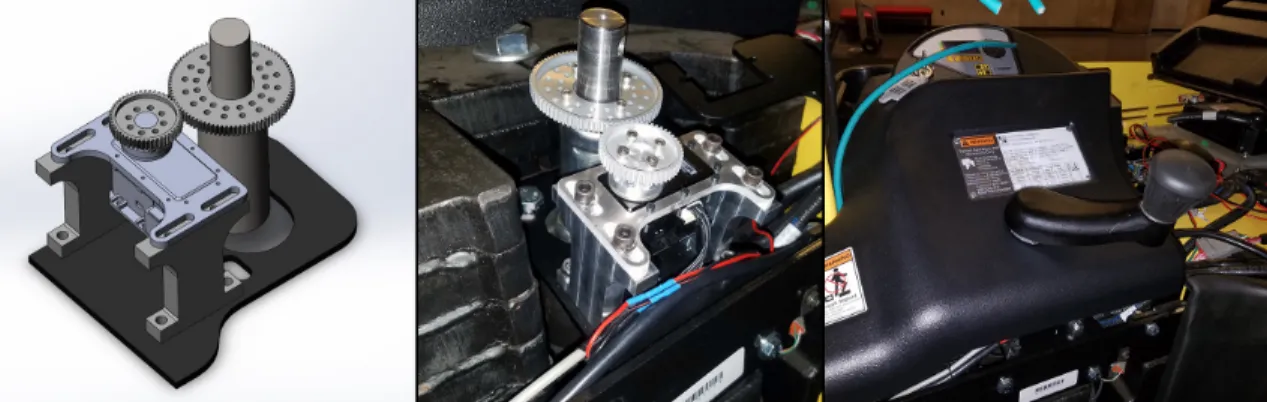
A Dynamixel MX-106 servo was attached via a 1.75:1 reduction gear to the steering tiller shaft, as shown in figure2-1. The OEM cover and tiller arm are then re-attached above the servo, retaining OEM manual steering capability. To steer manually, the servo is disabled from software, allowing it to be back-driven when the tiller arm is turned. A ROS node on the onboard computer runs a secondary P-controller based on wheel angle on top of the servo’s built in PID velocity controller and accepts target wheel angle commands. Hence, higher level control nodes simply command steer angles. These control nodes are, however, responsible for being aware of, and planning for, steering slew times and delays. Moving from full steering lock in one direction to the other (a 180 degree arc) takes several seconds. Real-time steering angle feedback is available in software via the CANBUS interface.
2.1.2
Mast Control
The forklift’s mast has three axes of freedom: lift, tilt and side-shift. All three axes are controllable via the CANBUS interface. However, there are no motion en-coders present and thus positional feedback is not possible without hardware modi-fication. For the reference implementation, we decided to forgo installation of mast feedback sensors and rely on a combination of mast-mounted camera feedback and dead-reckoning. In our tests, this system of control is sufficient for pick-and-place
Figure 2-1: Servo-drive steering modifications. Left: CAD assembly. Center: servo assembly installed on vehicle. Right: Factory cover re-installed.
tasks involving pallets placed on the ground. For over-head manipulation, the addi-tion of feedback sensors will be highly beneficial.
2.2
Onboard Computing
To enable autonomy, a desktop PC running Ubuntu linux is mounted onboard the vehicle. Robot Operating System (ROS)[8] is selected as the main development frame-work onboard the forklift. Low-level ROS "driver" nodes expose the vehicle’s fly-by-wire interface as well as sensor information via ROS topics. All autonomy logic, including the CANBUS interfacing for vehicle control, sensor interfacing and pro-cessing, and other software tasks are performed on this PC. The PC interfaces to the vehicle and onboard sensors via a mix of USB, and Ethernet connections. Full specifications for the onboard PC are provided in table 2.1.
Connectivity between the vehicle, sensors, and onboard computer is accomplished
CPU Intel i7-7820X
RAM 32GB DDR4 PC4-27200 GPU Nvidia GeForce 1080TI Motherboard ASUS ROG STRIX X299-E Storage 1TB Samsung NVME Networking
1x - 1000-Base Ethernet 1x - 802.11AC Wireless
4x - 1000-Base w/802.3at POE (ST4000PEXPSE) Table 2.1: Onboard PC Specifications
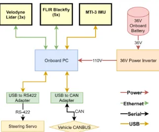
Figure 2-2: Computer connectivity block diagram outlining how various sensors in-terface to the onboard computer.
as outlined in figure 2-2.
2.3
Sensors
A number of sensors are retrofitted to the vehicle to enable obstacle detection, pallet perception, and planning. Sensors outfitted on the vehicle include five RGB cameras, three 3D laser scanners, and an IMU. Additionally, sensor readings are taken from the built-in wheel encoders and steering angle encoder. The sensor layout is depicted in fig. 2-3
Figure 2-3: Layout of sensors retrofitted to vehicle. Sensors are configured as follows: two forward-facing RGB cameras in a stereo configuration, an XSENS IMU near the vehicle center-point, two vertically oriented velodyne puck lidars mounted on the protective cage, a rear-facing velodyne puck lidar near the ground, and three cameras mounted to the protective cage facing aft, right, and left.
RGB Cameras
The RGB cameras are FLIR Blackfly GigE color cameras. The cameras use a sensor format of 1/1.2" and make use of 2.3 megapixel Sony IMX249 imaging sensors for a maximum resolution of 1900x1200 at 41 frames per second. Tamron M112FM08 8mm F2.4 lenses are coupled to the cameras, yielding a horizontal field-of-view of 75 degrees. There are two mast-mounted forward-facing cameras, and one fixed-mounted camera facing in each other direction (rear, right and left). Camera coverage is depicted in fig. 2-4
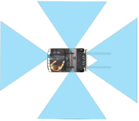
Figure 2-4: Depiction of RGB camera sensor coverage. Coverage map can be inter-preted as a 2D floor projection of the camera sight lines.
Laser Scanners
For 3D laser scanners, two Velodyne VLP-16 and one Velodyne VLP-16 Hi-Res are used. The high resolution model is used at the rear of the vehicle, in horizontal configuration. The two VLP-16 standard models are used on either side of the vehicle, in vertical configuration. Laser scanner coverage is depicted in fig. 2-5
Figure 2-5: Depiction of lidar sensor coverage. Coverage map can be interpreted as a 2D floor projection of the lidar’s field of view. The two polygonal regions represent the sensing region for the two vertically mounted lidars. The circular region at the rear of the vehicle represents the rear-mounted horizontal lidar.
IMU
The IMU used is an XSens MTI-3-DK-ND. The XSens is a MEMS AHRS system that is capable of onboard processing using the XKF3 sensor fusion algorithm, which fuses 3D magnetometer, accelerometer and gyroscope data. Since the forklift operates in an indoor environment with the potential for magnetic interference, the EKF is set to a configuration profile that places low trust on magnetometer measurements. The yaw of the forklift, as measured by the IMU, is fed to the main state estimation module.
The IMU has several different modes and profiles and has a stated yaw drift of <1 deg per 60 minutes in unreferenced mode (no magnetic input). The sensor is selected for it’s easy integration and ability to provide heading information without off-board processing.
Encoders
The drive wheel encoders and steering angle encoder are read through the vehicle’s CANBUS interface directly, and exposed as an ROS topic. The ROS interpreter node simple reads encoder counts and voltages and translates them to units of radians and meters per second.
2.4
Power Management
All systems are powered from the vehicle’s main battery, a large 36V lead-acid battery. The vehicle has a large solenoid which is activated with the ignition switch. DC-DC stepdown regulators provide power for onboard actuators and sensors. Step-downs are present for switched and unswitched 12v power and switched 5v power. In addition, a 600W 120V inverter is used to power the onboard computer. Resettable circuit breakers are included on both the switched and unswitched circuits. The onboard power management system is depicted in figure 2-6
Figure 2-6: Onboard power management for sensors and computing system. All power is drawn from the onboard main battery. Left: annotated photo of power management additions. Right: Schematic diagram of power management system.
2.5
Safety
There are a number of inherent risks in running a 5-ton autonomous vehicle and research platform. To prevent software, hardware, or sensor bugs and failures from causing an accident, several safety precautions and measures were implemented.
One key decision regarding safety is to always have an operator onboard the vehicle, even when under autonomous control. This operator has the best possible situational awareness, and can physically shut down or take control of the vehicle if necessary.
At the highest level, in software, several watchdog timers ensure that software nodes responsible for sending drive commands cannot fail or crash in a way which causes a latched or frozen drive command to reach the drivetrain.
Next, the drivetrain software module requires active input on a wireless joystick from an operator. One button must be held down to allow autonomous driveline commands to reach any actuators. A second button can be held to allow manual control. If neither button is held, the vehicle cannot move. Additionally, the vehicle’s brake-enable foot switch is active at all times and overrides all other commands.
features delivered with the vehicle from Hyster are left intact. The onboard computing system and autonomous logic have no way of overriding OEM safety measures. These measures include a hardware E-Stop button as well as a laser-based operator detection system. If no operator is present and positioned correctly to operate the vehicle, the vehicle will not move. If the vehicle is moving and the operator steps out, the vehicle will immediately stop.
With the present safety measures and safety plan in place, the onboard operator is always able to safety stop or shut down the vehicle regardless of the state of the onboard computer or software. No software glitch or bug on the onboard autonomy computer can result in a situation where the vehicle is out of control and cannot be easily stopped or shut down.
2.6
Sensor Use-Cases & Rationale
The aforementioned sensor suite includes considerations for future research problems and extended functionality. As such, not all sensors are used in the reference & test implementation provided as part of this thesis. Below are the various use-case scenarios which were considered when designing the current sensor layout.
2.6.1
Global Navigation
In a warehouse environment, it is anticipated a form of indoor positioning system, either based on radio transponders or fiducial markers will be preferred. For the described reference implementation, a fiducial marker system is used. The onboard cameras are used to detect the markers, with a database of known marker positions used to infer vehicle location.
Purely laser-based or camera-based approaches, such as particle filters or SLAM, are likely to be less effective in a warehouse setting. In a warehouse setting, ob-served objects shift frequently as pallets are moved, loaded, and unloaded. Addi-tionally, warehouses contain many repetitive structures. For example, a warehouse may have dozens of near-identical isles. The repetitive, and ever-changing nature of
the environment is not conducive SLAM-type approaches, and it would be difficult to deterministically infer the vehicles position without navigating first to a unique landmark.
2.6.2
Laser-Based Collision Avoidance
The onboard rear-facing laser scanner can be used for obstacle avoidance when in transit between warehouse regions. The scanner covers an approximate 200 degree arc in the direction of vehicle travel and can detect people, pallets, racking, and other obstacles down to floor level. The laser scanner can also be used to detect discontinuities in the floor surface ahead and detect drop-offs (for example, the edge of a loading dock).
2.6.3
Camera-Based Collision Avoidance
As RGB cameras are very inexpensive, there is significant industry interest in moving to camera-based sensing solutions. A key aspect of this goal is the development of robust collision avoidance which relies solely on RGB cameras, removing the need for expensive laser scanners in production vehicles. With recent progress in object detection and scene understanding using deep learning techniques, a camera-only implementation would be an interesting research direction to investigate.
2.6.4
Navigation in Three-Dimensional Confined Spaces
The two vertically oriented laser scanners enable development of path-planning al-gorithms for tight and confined spaces. For example, spaces with overhead obstacles such as racking or overhanging pallets. The vertical laser scanners are able to detect obstacles ahead of, behind, and directly beside the vehicle.
2.6.5
Camera-Based Pallet Manipulation
Similar to camera-based collision avoidance, the ability to detect and manipulate pallets using a strictly camera-based pallet detection algorithm is of interest. By
performing both manipulation tasks and collision avoidance with only RGB cam-era sensor inputs, the sensor cost for an autonomous vehicle could be dramatically reduced.
2.6.6
Precision Pallet Manipulation
A potential area for research, where currently available AGVs lack capability, is pre-cision pallet manipulation in dense three-dimensional environments. For example, cluttered racking or stacked pallets. This scenario is commonly encountered in ware-houses when unloading trucks or manipulating pallets on and off racking or other vertical storage. In these scenarios, the vehicle must understand the 3D space avail-able, and plan a manipulation strategy that does not cause the vehicle, manipulation forks, or the manipulated pallet to collide with obstacles in the environment such as other pallets, overhanging obstacles, or racking.
Chapter 3
Reference Software Implementation
The Onboard software makes use of the ROS (Robot Operating System) framework, and is written in a combination of Python and C++. The ROS framework[8], an industry standard in autonomous systems, allows easy inter-process communication as well as access to a large library of open source software packages for robot navi-gation, planning, estimation and other useful utilities. In the context of this project, ROS allows collaborators to quickly write software "nodes" or small programs that can easily interface with the vehicle, and it’s existing software stack. Additionally ROS comes pre-loaded with useful visualization software (RVIZ) and a coordinate transformation and book-keeping system (TF).
In the following sections, we describe the reference implementation created as part of this thesis to demonstrate a useful set of basic autonomous vehicle functionality as well as provide the tools necessary for research into specific areas such as perception, navigation and planning.
3.1
Node Architecture
Figure 3-1 depicts the reference implementation node graph. Flow of information originates at the sensor drivers and the central queue-based planner. The planner activates various nodes, and sensor inputs determine node behavior.
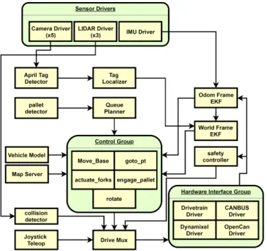
Figure 3-1: A graphical representation of the ROS node graph. Each yellow block represents an individual node. Green boxes group logically related nodes together, but are purely conceptual with no counterpart in implementation. Black arrows indicate communication between nodes.
3.2
Coordinate Frame System
The forklift software makes use of ROS’s TF2 coordinate frame book-keeping and transformation system[9]. TF2 allows any ROS node on the forklift to access any relevant data in any desired coordinate frame at any time, present or past. For example, a node can pose queries such as "what was the transform between the fork frame and base frame 3 seconds ago" or "give me the 3D laser scan data from the rear laser scanner in the odometry coordinate frame".
There are two world coordinate frames, "world" and "odom". These frames are described in detail in the estimation section below. Additionally, there are a number of frames defined for the vehicle itself. The main coordinate frame used for planning is the base_link frame, located between the two drive wheels on the ground plane. By convention, the X axis points forward and the Z axis points up. Each movable link receives its own coordinate frame, which is defined in a URDF (Unified Robot Description Format) file. In particular, the steering wheel and lifting forks receive
their own coordinate frames to track their motion. Additionally, each sensor has its own coordinate frame to allow simple transformation between the sensor coordinate frame, and any other coordinate frame. Generally, sensor data is transformed by nodes operating on the data to either the base_link frame, or odom frame.
3.3
Control
Control of the vehicle is achieved through the use of one of several available "mo-tion" nodes. Additional motion nodes may be added to the architecture to extend functionality and add new behaviors. Currently, motion nodes fall broadly into one of two categories: motion primitives, and move_base plugins.
Motion primitives are stand-alone nodes capable of simple motion behaviors that perform specific movements without complex planning. For example, the goto_pt motion primitive simply moves the vehicle directly towards the requested point in a given coordinate frame without knowledge of any map.
All motion nodes expose a ROS action interface [10], which allows the planner (or other node) to dispatch a specific action to a specific motion node. For example, a "goto point (1,1)" action could be dispatched to the "goto_pt" motion primitive with arguments (1,1). Motion node actions either complete with a success status code upon the motion node achieving its goal, or fail with one of several error codes. Current supported error codes include a timeout error (goal not achieved in max allowable time), goal not achievable error (valid plan not found, or arguments to motion node are invalid), and general failure (all other failures). Motion nodes, rather than the planner, are responsible for their own recovery behaviors (if any are provided) and failures are considered irrecoverable.
Each motion node sends its own independent drive signals, which are combined using a many-to-one muxing node. The muxing node additionally implements pri-ority management, a watchdog system, and a safety signal system. The pripri-ority management scheme prevents multiple nodes from broadcasting conflicting drive sig-nals. Only a single drive signal can reach the drivetrain at any given time. In the
event two nodes publish drive commands, the node assigned higher priority gains control of the drivetrain. In the event the highest priority node stops publishing com-mands, upon expiration of the watchdog timer, the next highest priority node gains control of the vehicle. The safety signal allows for top-level shutdown of all motor functions. There are two safety signals, a "teleop" signal, and an "autonomous" sig-nal. The teleop signal overrides the autonomous signal in the event both are present. The teleop signal must be present for any teleop command to reach the drivetrain. The autonomous signal must be present for any autonomous operation. The signal works as a heartbeat signal, with watchdog timeout. A heartbeat must be received at minimum every 100ms with a valid up-to-date timestamp for the corresponding functionality to remain active.
3.3.1
Move Base Motion Planning
Move_Base is a popular ROS package for mobile base path planning. The pack-age provides a common plugin architecture and action interface for global and local planners. Move_Base works by accepting a movement action, and dispatching the goal state to a global planner for a collision-free plan. Then, a local planner is used to compute real-time drive commands to track the global plan. Global and local planners connect to Move Base via a plugin architecture.
For global planning, the forklift currently utilizes a simple A* grid planner that looks at a pre-known global map to generate a collision free path to the goal. The A* planner does not take into account vehicle dynamics or the forklift’s non-holonomic constraints. Planned future work includes a custom RRT planner that accounts for the forklift’s dynamics.
For local planning, the TEB Local Planner plugin is used. TEB Local Planner uses a trajectory optimization method called Timed Elastic Bands. The approach is described by Rosmann et al. in their papers, "Trajectory modification considering dynamic constraints of autonomous robots" [11] and " Efficient trajectory optimiza-tion using a sparse model" [12]. Subsequent papers describe extensions made to TEB that allow planning for car-like robots and prevent the algorithm from getting stuck
in local optima [13][14][15]. The planner was selected as it is capable of planning for car-like robots with non-holonomic constraints, such as the three wheel forklift platform.
3.3.2
Goto Point Motion Primitive
The Goto Point motion primitive is a stand-alone motion node that takes as a goal argument a coordinate frame and an x and y position. The node then attempts to move the vehicle directly to this location, without regard for obstacles. Drivetrain commands are computed via a simple P-controller with a couple modifications to account for steering rates and hysteresis.
The control law uses the following parameters: 𝐾𝜃
𝐸𝑃 𝐻𝐼_𝑁 𝑂𝑀 𝐼𝑁 𝐴𝐿 𝐸𝑃 𝐻𝐼_𝑀 𝐴𝑋
𝐾_𝑆𝑉
The control law is as follows: 𝜑 = 𝐾𝜃𝐸𝜃 𝜑𝑒𝑟𝑟 = 𝑎𝑏𝑠(𝜑 − 𝑠𝑡𝑒𝑒𝑟𝑖𝑛𝑔_𝑎𝑛𝑔𝑙𝑒) 𝑆𝑡𝑒𝑒𝑟_𝑒𝑟𝑟_𝑣𝑒𝑙_𝑚𝑜𝑑 = 𝑚𝑎𝑥(0.1, 𝑚𝑖𝑛(1, ((𝜑𝑒𝑟𝑟−𝐸𝑃 𝐻𝐼_𝑁 𝑂𝑀 𝐼𝑁 𝐴𝐿)/(𝐸𝑃 𝐻𝐼_𝑀 𝐴𝑋− 𝐸𝑃 𝐻𝐼_𝑁 𝑂𝑀 𝐼𝑁 𝐴𝐿)))) 𝑆𝑡𝑒𝑒𝑟_𝑎𝑛𝑔𝑙𝑒_𝑣𝑒𝑙_𝑚𝑜𝑑 = 𝑚𝑎𝑥(0.1, 𝑚𝑖𝑛(1 − 𝑎𝑏𝑠(𝜑)𝐾_𝑆𝑉, 1)) 𝑉 = 𝑣𝑚𝑎𝑥* 𝑠𝑡𝑒𝑒𝑟_𝑎𝑛𝑔𝑙𝑒_𝑣𝑒𝑙_𝑚𝑜𝑑 * 𝑠𝑡𝑒𝑒𝑟_𝑒𝑟𝑟_𝑣𝑒𝑙_𝑚𝑜𝑑
3.3.3
Actuate Forks Motion Primitive
The Actuate Forks motion primitive is a simple node which allows control of the lifting forks. The reference implementation only makes use of the lift axis, so the current revision of this node allows simple lifting velocity commands on the lifting forks’ Z
axis. In a future revision, this node will also enable control of the side-shift and tilt axes as well as an option for positional control rather than velocity commands.
3.3.4
Rotate In Place Motion Primitive
The Rotate In Place motion primitive accepts a target heading as it’s input argument, and rotates the vehicle in its current position to the requested orientation. The rotation is achieved by slewing the steering wheel to a 90-degree offset and then sending velocity commands via a simple P-controller to rotate the vehicle. Rotation can be commanded either in a relative frame, or with respect to the global coordinate frame.
3.3.5
Engage Pallet Motion Primitive
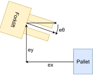
The Engage Pallet motion primitive is a non-linear feedback controller, first described by Walter et.al. in their paper, ’Closed-Loop Pallet Manipulation in Unstructured Environments’ [16]. The steering control law is computed as follows:
𝛿 = 𝐾𝑦tan−1(𝑒𝑦) + 𝐾𝜃𝑒𝜃
Where 𝐾𝑦 and 𝐾𝜃 are tunable parameters and 𝑒𝑦 and 𝑒𝜃 describe the current amount
of error in alignment. 𝑒𝑦 is the amount of lateral error, with respect to a line extended
normal to the face of the pallet, and originating at its center point. 𝑒𝜃 is the amount
of angular misalignment between the forklift and the pallet. This arrangement is depicted in Figure 3-2. This non-linear controller is known to converge such that both 𝑒𝑦 and 𝑒𝜃 approach zero, when 𝑒𝜃 ∈ −𝜋2,𝜋2.
Figure 3-2: Schematic view of variables used for pallet engagement algorithm.
3.4
Perception
3.4.1
Pallet Detection
For the reference implementation, a trivial april tag based pallet detector is included. An april tag is affixed to the forward face of a pallet, and the ID of this tag provided to the pallet detection node. Upon viewing this tag, the node publishes the location of the tag as a pallet. The april tag detection library is described further in the April Tag Localization section.
3.4.2
Obstacle Detection
Obstacle detection in the reference implementation is a simple pipeline which converts 3D point cloud data from the rear-mounted velodyne into a 2D occupancy grid, then uses the occupancy grid to detect imminent collision and set a flag if collision is imminent. The 2D occupancy grid is a small localized map, of tunable resolution and size, affixed to the vehicle’s base_link coordinate frame. Cells take binary values of occupied or unoccupied, with a threshold for number of laser returns required to flip a cell from unoccupied to occupied. The collision detection node then takes in the occupancy grid, and sends a "stop" message to the drive muxer at highest priority level in the event a collision is imminent, overriding any active drivetrain commands.
Once the collision risk has cleared, the node will stop publishing drive messages, reverting control to whatever autonomous node was active prior to the collision risk. The reference obstacle detection node has significant limitations. In particular, the node has no knowledge of the current planned trajectory. As a result, the node will give false positives when maneuvering in tight spaces. Therefore, when employing a motion planning stack, the obstacle detection node should be disabled, and the motion planner should take over the task of collision avoidance.
3.4.3
Estimation
The vehicle maintains two coordinate frames for navigation - the odometry frame and the world frame. The odometry frame is piecewise continuous and generated through integrating odometry and IMU data via a Kalman Filter. The world frame fuses measurements from the tag-based localizer to provide a consistent global frame that matches a pre-surveyed map. The tag measurements are fused via secondary Kalman Filter. The world frame is subject to discrete jumps and therefore not suitable for tasks that require a piecewise continuous coordinate frame. The world frame is used for global navigation and path planning tasks. The odometry frame is used for pallet manipulation and localized perception-based movements, such as relative translations or rotations.
Kalman Filter
Filtering of sensor measurements are performed using an EKF (Extended Kalman Filter). An existing EKF implementation from the ROS package library, the "Robot Localization" package, was used for filtering. The Robot Localization package sup-ports fusing data from common ROS message types including IMU and odometry messages. Table 3.1 tabulates the filter inputs used in the reference implementation.
Measurement Source Filter Inputs provided Odometry Odom Velocity: x, y, 𝜃 IMU Odom Position: 𝜃 Tag Localizer World Position: x,y,𝜃
Table 3.1: ROS "Robot Localization" EKF package inputs.
Odometry
Odometry is read from the drivetrain as a left and right encoder count. The drivetrain driver node reads the wheel encoder counts and converts these to a ROS "Odometry" message which provides a vehicle velocity and rate of turn.
Tag Localizer
The Tag Localizer consists of two components: a fiducial marker detection system and a marker look-up and reverse-transform system that infers vehicle position from an observed marker. The tag localizer makes use of AprilTag, a popular fiducial marker system developed by Edwin Olson[17]. Tag detection is performed using M. Kaess’ AprilTags C++ library[18]. The output of the tag detector is the tag’s unique ID and a position and orientation in 3D space, relative to the camera used for detection. This position and orientation, along with the tag ID are then sent to the tag localizer node. The localizer computes the transform from the vehicle base_link to the tag in 2D space. Then, the tag location database is used to compute the reverse transform between the tag’s known location in the global frame to the estimated vehicle location in the global frame, given the observation.
3.5
Planning
3.5.1
Queue Planner
Scheduling and planning is performed by a queue-based task planner. The planner sequentially dispatches tasks to worker nodes via a ROS action interface, and waits for completion before moving to the next task. Each worker is responsible for its
own appropriate recovery behavior. An unrecoverable task is considered anomalous behavior and causes the planner to abort execution of the current queue. The planner supports two types of tasks: subroutines and task primitives. Subroutines are made up of several primitives (or other subroutines) and can be loaded at runtime with arguments to achieve high level behavior. Subroutines include actions such as ’Move to area A and detect pallet’, or ’Pick and place pallet from location ABC to staging bin 123’. Primitives include the following actions:
∙ goto_pt: Move to a world frame waypoint defined by x,y.
∙ engage: Engage a pallet at location defined by x,y,theta.
∙ rotate: Rotate the vehicle to a specific orientation defined by theta.
∙ lift: Raise or lower the vehicle forks, defined by a direction boolean.
∙ wait: Wait for a specified duration, defined by an integer.
Chapter 4
Results and Conclusion
4.1
Results
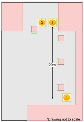
The overall system was evaluated by performing an end-to-end pick and place task. The objectives of the test are to verify performance and reliability of the vehicle’s fly-by-wire systems, and demonstrate the reference software implementation. The vehicle was tasked with navigating to a bay containing a pallet, picking it up, then placing it in another bay. The test was conducted in an underground loading dock at the MIT campus. A schematic view of this test area is included in Figure 4-1. The test was conducted as follows:
1. The vehicle begins parked at one end of the loading dock, with a view of at least one localizing tag so the vehicle is able to obtain a position fix (location 1 in Figure 4-1).
2. Upon receiving a trigger signal, the vehicle begins an autonomous pick and place cycle.
3. The vehicle positions itself in front of one of the loading dock bays (location 2 in Figure 4-1), and commences pallet detection and engagement.
4. After pallet engagement, the vehicle moves to the drop-off area (location 3 in Figure 4-1). Due to limited space as we are testing in an active loading dock,
the drop-off area and parking area share a single loading bay.
5. The pallet is placed at the drop-off location and the vehicle returns to the parked position (location 1 in Figure 4-1).
In these tests, the vehicle was able to reliably perform multiple pick & place cycles autonomously. A video of this test sequence is available on YouTube at the following URL: http://goo.gl/AsdL27 [19] . For safety reasons, a low maximum speed limit (less than 1.0𝑚/𝑠) was set on the vehicle. A goal of future research is to increase vehicle speed limits and efficiency of path planning, so the vehicle may perform at rates similar to that of a skilled human operator.
Figure 4-1: The layout used for a complete end-to-end pick and place task. The numbered orange circles represent the following: 1) parked position for the vehicle. The forklift parks here between pick and place cycles. 2) The location from which the pallet engagement cycle is started. 3) the location for pallet drop-off. Dimensions are in meters. Green boxes represent localization tags.
4.2
Conclusion and Future Work
In this thesis, I present an autonomous forklift research platform, and a reference software implementation with the objective of providing an autonomy platform for researchers to further the state of AGV capability in partially automated warehouses. The platform lends itself to research in several directions. Future directions for de-velopment include human-robot interaction, obstacle detection, planning, estimation, and 3D manipulation. Advances in AGV autonomy have the potential to increase warehouse productivity by decreasing the cost and increasing the utility and possible use-cases of AGVs.
In initial tests, the forklift AGV was able to reliably operate under computer control using a ROS software stack. It navigated a warehouse setting using AprilTag markers affixed to the walls for global localization as well as wheel encoders and an accelerometer for precisely controlling and tracking its movements. In current form, the vehicle successfully delivers reliable, functional autonomous hardware and a fully functional software stack to enable further research in specific areas of autonomy.
Bibliography
[1] J. Gu, M. Goetschalckx, and L. F. Mcginnis, “Research on warehouse operation: A comprehensive review,” European Journal of Operational Research, vol. 177, no. 1, p. 1âĂŞ21, 2007.
[2] D. Culler and J. Long, “A prototype smart materials warehouse application im-plemented using custom mobile robots and open source vision technology devel-oped using emgucv,” Procedia Manufacturing, vol. 5, p. 1092âĂŞ1106, 2016. [3] M. R. Walter, M. Antone, E. Chuangsuwanich, A. Correa, R. Davis, L. Fletcher,
E. Frazzoli, Y. Friedman, J. Glass, J. P. How, and et al., “A situationally aware voice-commandable robotic forklift working alongside people in unstructured out-door environments,” Journal of Field Robotics, vol. 32, no. 4, p. 590âĂŞ628, 2014. [4] J. Kim and H. Jun, “Vision-based location positioning using augmented reality for indoor navigation,” IEEE Transactions on Consumer Electronics, vol. 54, no. 3, p. 954âĂŞ962, 2008.
[5] G. VasiljeviÄĞ, D. MikliÄĞ, I. Draganjac, Z. KovaÄŊiÄĞ, and P. Lista, “High-accuracy vehicle localization for autonomous warehousing,” Robotics and Computer-Integrated Manufacturing, vol. 42, p. 1âĂŞ16, 2016.
[6] “E30-40hsd3 3-wheel electric forklifts.” [Online]. Avail-able: http://www.hyster.com/north-america/en-us/products/3-wheel-electric-trucks/E30-40HSD3/
[7] “Usb can bus adapter cpc-usb/arm7 v2.0.” [Online]. Available: https://www.traquair.com/products/can/cpc-usb.html
[8] “About ros.” [Online]. Available: http://www.ros.org/about-ros/
[9] T. Foote, “tf: The transform library,” in Technologies for Practical Robot Ap-plications (TePRA), 2013 IEEE International Conference on, ser. Open-Source Software workshop, April 2013, pp. 1–6.
[10] E. Marder-Eppstein and V. Pradeep, “actionlib.” [Online]. Available: http://wiki.ros.org/actionlib
[11] C. Rösmann, W. Feiten, T. Wösch, F. Hoffmann, and T. Bertram, “Trajec-tory modification considering dynamic constraints of autonomous robots,” in ROBOTIK, 2012.
[12] ——, “Efficient trajectory optimization using a sparse model,” 2013 European Conference on Mobile Robots, pp. 138–143, 2013.
[13] C. Rösmann, F. Hoffmann, and T. Bertram, “Planning of multiple robot tra-jectories in distinctive topologies,” 2015 European Conference on Mobile Robots (ECMR), pp. 1–6, 2015.
[14] ——, “Integrated online trajectory planning and optimization in distinctive topologies,” Robotics and Autonomous Systems, vol. 88, pp. 142–153, 2017. [15] ——, “Kinodynamic trajectory optimization and control for car-like robots,” 2017
IEEE/RSJ International Conference on Intelligent Robots and Systems (IROS), pp. 5681–5686, 2017.
[16] M. R. Walter, S. Karaman, E. Frazzoli, and S. Teller, “Closed-loop pallet manipu-lation in unstructured environments,” 2010 IEEE/RSJ International Conference on Intelligent Robots and Systems, 2010.
[17] E. Olson, “AprilTag: A robust and flexible visual fiducial system,” in Proceed-ings of the IEEE International Conference on Robotics and Automation (ICRA). IEEE, May 2011, pp. 3400–3407.
[18] M. Kaess, “Apriltags c library.” [Online]. Available: http://people.csail.mit.edu/kaess/apriltags/
[19] R. Baird, “Mit-jd-rhino milestone 1,” Jun 2018. [Online]. Available: http://goo.gl/AsdL27