Publisher’s version / Version de l'éditeur:
Vous avez des questions? Nous pouvons vous aider. Pour communiquer directement avec un auteur, consultez la première page de la revue dans laquelle son article a été publié afin de trouver ses coordonnées. Si vous n’arrivez pas à les repérer, communiquez avec nous à PublicationsArchive-ArchivesPublications@nrc-cnrc.gc.ca.
Questions? Contact the NRC Publications Archive team at
PublicationsArchive-ArchivesPublications@nrc-cnrc.gc.ca. If you wish to email the authors directly, please see the first page of the publication for their contact information.
https://publications-cnrc.canada.ca/fra/droits
L’accès à ce site Web et l’utilisation de son contenu sont assujettis aux conditions présentées dans le site LISEZ CES CONDITIONS ATTENTIVEMENT AVANT D’UTILISER CE SITE WEB.
10th International Vacuum Insulation Symposium: 15 September 2011, Ottawa,
Ontario [Proceedings], pp. 68-76, 2011-09-15
READ THESE TERMS AND CONDITIONS CAREFULLY BEFORE USING THIS WEBSITE. https://nrc-publications.canada.ca/eng/copyright
NRC Publications Archive Record / Notice des Archives des publications du CNRC :
https://nrc-publications.canada.ca/eng/view/object/?id=0f7c463d-d946-40ac-9bd9-1f38b161fadc https://publications-cnrc.canada.ca/fra/voir/objet/?id=0f7c463d-d946-40ac-9bd9-1f38b161fadc
NRC Publications Archive
Archives des publications du CNRC
This publication could be one of several versions: author’s original, accepted manuscript or the publisher’s version. / La version de cette publication peut être l’une des suivantes : la version prépublication de l’auteur, la version acceptée du manuscrit ou la version de l’éditeur.
Access and use of this website and the material on it are subject to the Terms and Conditions set forth at
Energy performance of highly insulated wood-frame wall systems
using a VIP
Maref, W.; Saber, H. H.; Glazer, R.; Armstrong, M. M.; Nicholls, M.;
Elmahdy, A. H.; Swinton, M. C.
Ene rgy pe rform a nc e of highly insula t e d w ood-fra m e w a ll syst e m s
using a V I P
N R C C - 5 4 5 2 0
M a r e f , W . ; S a b e r , H . H . ; G l a z e r , R . ; A r m s t r o n g ,
M . M . ; N i c h o l l s , M . ; E l m a h d y , H . ; S w i n t o n , M . C .
S e p t e m b e r 2 0 1 1
A version of this document is published in / Une version de ce document se trouve dans:
10th International Vacuum Insulation Symposium, Ottawa, Ontario, September
15-16, 2011, pp. 68-76
http://www.nrc-cnrc.gc.ca/irc
The material in this document is covered by the provisions of the Copyright Act, by Canadian laws, policies, regulations and international agreements. Such provisions serve to identify the information source and, in specific instances, to prohibit reproduction of materials without written permission. For more information visit http://laws.justice.gc.ca/en/showtdm/cs/C-42
Les renseignements dans ce document sont protégés par la Loi sur le droit d'auteur, par les lois, les politiques et les règlements du Canada et des accords internationaux. Ces dispositions permettent d'identifier la source de l'information et, dans certains cas, d'interdire la copie de documents sans permission écrite. Pour obtenir de plus amples renseignements : http://lois.justice.gc.ca/fr/showtdm/cs/C-42
ENERGY PERFORMANCE OF HIGHLY INSULATED WOOD-FRAME
WALL SYSTEMS USING A VIP
Wahid Maref
1, Hamed Saber
1, Rock Glazer
1, Marianne Armstrong
1,
Mike Nicholls
1, Hakim Elmahdy
1and Mike Swinton
11
National Research Council Canada, Ottawa, Canada
Abstract
Despite recent advances in highly performing envelopes that are technically feasible and can reduce heat loss by about one half, most current construction still just meets the provincial building code minimum of 2” x 6” constructions with conventional batt insulation. This project addresses several barriers to the adaptation of new envelope systems, including issues of buildability, incremental cost of labour, materials, and wall system energy performance assessment.
The National Research Council of Canada’s Institute for Research in Construction (NRC-IRC) is a partner in the PERD (Program on Energy Research and Development) Project with NRCan and PWGSC on “Next Generation Building Envelope Building Systems”. This project deals with thermal performance of eco-friendly advanced thermal insulation materials integrated into wall assemblies that are adapted for Canadian wood frame construction. The current project is looking at laboratory, field testing and modeling of highly insulated wall assemblies. The work consists of evaluating the thermal performance of different High-R-value wall systems as well as different retrofit strategies by adding innovative thermal insulation on the exterior such as Vacuum Insulated Panels (VIP). The objective of this project is to develop recommended construction specifications and guidelines for assembling next generation building envelope systems with the ultimate goal of encouraging their use in Canadian wood frame construction.
1. Introduction
The energy crisis in the 70’s had major effect on our building technology related to energy efficiency. Thermal insulation of buildings became the key element to minimize heat losses and to improve energy performance. Much more thermal insulation was placed in exterior walls, and the need for a
corresponding increase in airtightness had started to get recognition.
Achieving better airtightness, high levels of envelope insulation will certainly be required, with wall R-values of more than 3.33 m2.K /W and roof R-values of more than 5.0 m2.K /W.
The drive to the reduction in energy use in new buildings is led by new regulations in Europe for example [1]. To achieve these new levels of energy performance with existing wall systems and materials, the wall systems could be considerably thicker and this may not be acceptable to consumers. In addition, this will lead to loss of usable floor area, greater weight, increase costs such as transport and time of
construction, as well as new challenges on the structures.
To overcome to those hurdles, a promising recent innovations in building technology is being investigated within the context of application in Canada - , the vacuum panel insulating systems. Due to their very high R-values, their potential is considered to be a promising way of insulating the building envelope to very high levels of thermal resistance while maintaining reasonable envelope thickness. The Vacuum
Insulating Panel (VIP) is of interest owing to its exceptional insulating R-value, up to R-60 per inch or even higher [2].
This concept is starting to gain interest by architects and building scientists and mainly for two reasons [3]:
1. To reduce the thickness of the insulating material, thus the wall assembly. With VIP, the insulation thickness can be reduced by a factor of 5 to 10 compared to conventional materials-with the same thermal insulation value.
2. To increase or enable insulation in critical constructions area (i.e. retrofit of exterior walls ) Despite their insulating values, VIPs have been slow to make inroads into construction because of three drawbacks: cost, the need to protect them against puncturing, and the absence of long-term performance data or procedure to predict their long-term performance.
Up till recently, Canadian and European research efforts have been mainly focused on the VIPs
themselves [4, 5, 6 and 7]. However, subsequent research started to investigate how to implement a VIP panel in building construction in such a way that the thermal advantages are fully used. This has been published in the IEA Annex 39 on High Performance Thermal Insulation [8] and [7 and 9]. It is important to study the interaction between the thermal insulation layer and the building component in which it is integrated into.
The VIP panel can be used in the retrofit of the existing house either at the interior or at the exterior [10]. It can also be used in new construction such as wood-frame construction in the double stud walls [11]. Most of the VIP activity in Canada is still in the R&D phase with some demonstration projects planned. Germany and Switzerland are the two first countries where a market in its early stage has been
established and have introduced VIP-Technology to building construction sector, through research efforts such as the IEA Annex 39 [8] as well as other R&D efforts [1, 12, 13 and 14]
In 2005 [1], VIP was used in cladding systems within new building envelopes in the industrial and commercial sector. Applications exist in at least three categories:
1. Mainstream industrial cladding systems where in terms of cost and performance systems must be competitive with conventional technology, and where the thickness of the panels is not a
decisive advantage.
2. Commercial building cladding where ‘thin wall technology’ can moderate the increase the net gross area of the building and consequently deliver higher rental yields.
3. Architectural applications where performance and appearance of the panels is advantageous, such as used in conjunction with structural glazing systems (i.e. curtain walls).
Since VIP technology is presently considerably more costly than established technology, improved production capacity and efficient manufacturing techniques are likely to be essential such as looking to alternative and less expensive core material of the VIP [4] thereby making the VIP a more cost-effective material for building envelope.
Based on research efforts of NRC-IRC and others, it appears that VIPs hold great promise for use in building construction in a way that could substantially reduce energy consumption [8].
Several prototype projects have been completed or being carried out in Europe using VIP technology [8]. Canada, a country with very cold climate, was in forefront of cold-climate insulating technology and renowned leader of research and development activities at that time. However, further technology developments in the area of insulation technology and recent global concerns about the climate change phenomena showed that there is room and need for improvement in the insulation technology for building envelopes. Hence, NRC-IRC and others organizations and laboratories around the world have established research programs and studies that focused on the applicability of high performance vacuum insulation panels (VIP) in building envelope construction.
2. Objectives and Scope
The main objective of this project is to develop recommended construction specifications and guidelines for assembling next generation building envelope systems with the ultimate goal of encouraging their use in Canadian construction, especially in wood-frame construction.
The scope of the project includes: 1) constructing wall samples insulated with poly-wrapped and sealed (glass fiber batts), as reference wall, and different types of VIPs; 2) performing thermal and air leakage tests on wall samples and 3) developing experimental details and recommended specifications for highly insulated walls using VIPs such as double stud walls for new construction and different pre-fabricated concepts panels for energy retrofit by adding insulation for example at the exterior of the sheathing board. The challenge for this type of construction using VIP is to maximize their protection from nails, screws and fasteners during assembly and as well after assembly from fasteners from exterior, nails and other penetrations for hanging shelving, frames, and other decorations on the interior finish.
Finally, the ultimate goal is to show the buildability using Canadian wood frame construction techniques in order to assess as-built performance.
3. Concept Development and Experimental Task
Through a series of consultations with project partners and industry stakeholders, a number of workable concepts were developed for wall constructions that feature one or two protected layers of VIPs and conventional wood framing techniques used for the load-bearing portion of the walls. Some of these concepts are presented below.
In the experimental task, laboratory testing is performed on each wall sample to determine: air leakage and thermal transmission coefficient (R-value). In addition, separate VIP material sample are prepared to conduct material characterization according to established standards. In some cases, the air leakage rate and R-value tests are performed before and after sample conditioning, as will be explained later.
3.1. Wall Description
In this paper two types of VIPs from different manufacturers were used to demonstrate the process of installation. Table 1 shows the different configurations and type of walls that were used in this series of experiments. The first wall tested as shown in Table 1 as a reference wall (REF) was constructed using conventional 2”by6” wood stud frame, and insulated with: Poly-lapped and sealed (glass fiber batts). The
overall dimension of the wall is 2.4 m by 2.4 m (as a standard size to fit the NRC-IRC Guarded Hot Box (GHB) apparatus). In all remaining walls, VIP panels were inserted between the double stud wall assemblies i.e. 2”x4” exterior and 2”x3” interior. Differences between configurations listed in Table 1 were in the details of wood-stud cavity some of which were insulated and some not. Table 1 also provides full description of the ten walls samples reported in this paper.
The Guarded Hot Box apparatus was used to perform tests on those different wall assemblies to measure their thermal performance R-values before and after performing the Air Leakage Test in accordance with CCMC Air Barrier Technical Guide 07272 [15]. Note that all tested walls were opaque walls with no penetrations, nor windows.
Figure 1 shows a schematic vertical cross section for concept 1 of double stud wall with VIP Type 1 with uninsulated (Glass fiber batts) wood stud cavities.
3.2. CONCEPT 1A – Double Stud Wall
The first concept that we developed is double stud walls. The VIPs are held in the middle of a double-stud wall. This concept could be tested with and without fibreglass batts in the exterior stud cavity.
Advantages:
- Central location of VIPS is less likely to be pierced by nails - Interior stud cavity can be left empty, to allow for ease of wiring Disadvantages:
- Difficult to replace damaged VIPs
- Labour and material intensive – like building two walls
- Thicker wall - approximately 250 mm, but relatively thin for the delivered R-value.
Figure 1: Concept 1A Wall Configuration (9 ¾” double stud; 3.5” batts both cavities)
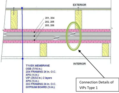
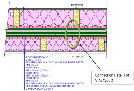
Figure 2 shows a schematic vertical cross section concept 1 of double stud wall with VIP Type 2 with insulated (Glass fiber batts) wood stud cavities.
Connection Details of VIPs Type 1
Figure 2: Concept 1G Wall Configuration (9 ¾” double stud; 3.5” batts both cavities) Table 1 Summary of wall description
3.3. Wall Sample Preparation
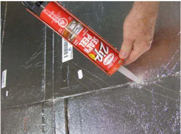
Figure 3 shows the installation of the first layer of VIP Type 2-Rounded edges (see Table 1). Figure 4 shows the installation of the staggered second layer of VIP Type 2-square edges.
TYVEK MEMBRANE OSB (7/16 in.)
2X4 FRAMING 24 in. O.C. with GLASS FIBRE BATTS XPS (½ in.) NEOPRENE VIP - 20 mm (25/32 in.) NEOPRENE VIP - 10 mm (13/32 in.) NEOPRENE XPS (½ in.)
2X3 FRAMING 24 in. O.C. with GLASS FIBRE BATTS POLYETHYLENE AIR & VAPOUR BARRIER GYPSUM BOARD (½ in.)
INTERIOR EXTERIOR
Connection Details of VIPs Type 2
The big challenges in this kind of installation (New Construction) were:
1. Samples that were provided by manufacturers were in different sizes and not optimized and normalized for typical North American wall type construction.
2. In laying out those VIP panels so that they could cover the whole surface of the wall (8’x8’) and, 3. In reducing or eliminating the air leakage by sealing edges and connections.
Through trial and error, with feedback from each experiment, new techniques were investigated to achieve superior performance at each stage. For example, VIPs with square edge insulation sandwiched first in thin neoprene layers (Figure 4) and then extruded polystyrene layers seemed to be the favourable approach to protect the VIPs during fabrication. Using caulking around the edges of the VIPs (see Figure. 5) also led to stability of the VIP pieces during assembly and good resultant air tightness and overall thermal performance.
Figure 5Sealing edges with silicone Figure 3- Installation of the first layer of VIP
Type 2-Rounded edges
Figure 4- installation of the staggered second layer of VIP Type 2-Rounded edges
Figure 6 shows how to seal the poly-lapped Air/Vapour Barrier meeting the requirement of part 9 of the National Building Code (NBC) [16] and how we insure the continuity of the designated Air Barrier (i.e. 6-mil Polyethylene).
Figure 6- Polyethylene Air & Vapour Barrier
sealed on perimeter Figure 7 - Surface thermocouples locations
(dimensions are in inch).
3.4. Instrumentation of Wall Assembly
Each wall is furnished with an array of thermocouples on interior and exterior surfaces in order to measure Surface-to-Surface R-value Standard Test that was performed in the GHB. Some interstitial thermocouples are also installed to measure the surface temperature of VIPs for future modeling purposes. Figure 7 shows the thermocouples mounted on the wall surface.
3.5. Test Sequence
Each wall sample is subjected to a series of tests. This included: • Air leakage test before conditioning,
• Sample conditioning,
• Air leakage test after conditioning and, • Thermal resistance test after conditioning.
It was decided not to measure the R-value before conditioning due to the insignificant impact of conditioning on the R-value for other types of walls [19].
3.6. Sample Conditioning
Each wall is conditioned (after initial air leakage) according to the CCMC gui
de 07272.
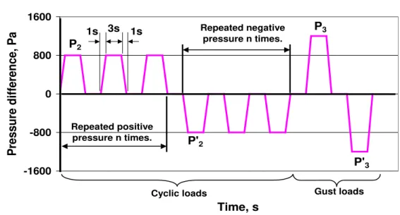
Figure 8 illustrates the conditioning pressure cycles.The wall sample is subjected to cycles of positive and negative pressure as follows (See Figure 8):
- A positive pressure rise from 0 to +800 Pa in 1 second remains constant for 3 seconds, down to 0 Pa in one second and remains at 0 Pa for 3 seconds. This cycle is repeated 800 times
- A negative pressure is applied from 0 to – 800 Pa in one second, remains at – 800 Pa for 3 seconds, increases to 0 Pa in 1 second, and remains at 0 Pa for 3 seconds. This cycle is repeated 800 times. - Gust wind: two cycles from 0 to + 1200 Pa (and another to – 1200 Pa) in a similar cycle.
Figure 8- A schematic of the pressure cycle during sample conditioning.
3.7. Material Characterization
The material characterization was performed using heat flow meter according to ASTM C-518-98 standard (ASTM 2004) [18] on all VIPs used in this project. The test specimens were placed horizontally in a 60 cm x 60 cm Heat Flow Meter apparatus. Heat flowed vertically upwards through the specimens during the tests. The thermal conductivity was determined at mean temperature of around 24 ± 1°C. Table 2 provides a summary of the results of VIPs used in different wall assemblies.
VIP Type Tmean (°C ) Thermal Conductivity
λ (W/m.K)
Type 1 24.0 0.0032
Type 2 24.1 0.00494
The thermal conductivity of the VIP is an average value of 5 samples.
3.8. Air Leakage Test Results
All wall samples are tested to determine their air leakage performance at different pressure differential [19]. Figure 9 shows a wall mounted in the air leakage tester. Also, the same test facility is used for the sample conditioning.
Following the mounting of the wall sample, the extraneous air leakage (system air leakage) is determined. Ideally, the extraneous air leakage should be less than 10% of the expected air leakage rate (as per the ASTM standard). After many modifications, the system now has zero extraneous air leakage.
Pressure cycle for sample conditioning
-1600 -800 0 800 1600 Time, s P ressu re d if fer en ce, P a P2 P'2 P3 P'3 Repeated positive pressure n times. Repeated negative pressure n times.
Cyclic loads Gust loads
3s 1s
1s
Figure 9– A Wall Sample Mounted in the Air Leakage Tester
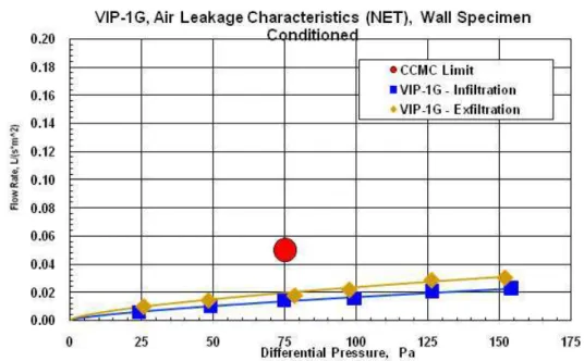
Figure 10 shows the air leakage characteristic of the wall VIP-1G after conditioning (see Table 1). The wall sample was subjected to a pressure difference that varied between 0 and ~150 Pa, and determine the air leakage rate. The CCMC Air Barrier Guide sets the maximum allowable air leakage rate for the product to be labeled as “air barrier”. This limit is set to 0.05 l/ (m2.s) at ∆P = 75 Pa. The results showed that the wall assembly is airtight and well below the CCMC limit @ 75 Pa.
Figure 10- Air Leakage Test Results for Wall VIP-1G after Conditioning
3.9. R-value Test Results
The R-values of all walls are determined in the NRC-IRC guarded hot box facility [20 and 21]. Figure 11 shows a picture of a wall mounted in the mask wall of the guarded hot box.
New aluminum
Frame Holder
Wall Specimen
Data Acquisition &
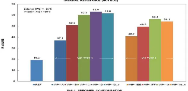
As indicated earlier, the R-value of some walls was determined after sample conditioning, since there was not a significant change in the R-value after conditioning compared to the values before conditioning. Also, the R-values were determined at a warm side temperature of 20±1°C while the cold side was maintained at -20±1°C and -35±1°C. Figure 12 is a bar chart showing the R-values (in ft2 hr o
F/BTU) of the ten walls at one set of temperature difference. Note that the uncertainty in the measured R-values in the GHB is within +6% GHB [22].
Figure 11 - Picture of a wall mounted in the mask wall of the guarded hot box and its IR Camera to show the temperature profile.
Figure 12- Wall Configuration with Concept 1- Protected Double Stud Summary of Laboratory results (R-Value)
4. Closing Remarks
With the new trend of building energy performance towards Net-Zero-Energy homes with highly
insulated walls, the use of VIP could have a role to play in promoting sustainable and eco-friendly houses. This research was undertaken in support of the uptake of next generation building envelope systems and will enable us to evaluate the innovative technologies in a new and existing housing and commercial building applications.
We learned from our laboratory testing that attention has to be paid to the handling to the edge effect in combination with surrounding material to achieve high levels of airtightness of the wall assembly. A new technique was found during this exercise to overcome to this hurdle using the neoprene on both sides of the VIP.
5. What is next
This on-going project is, at time of writing, continues to evaluate different wall assemblies with different concepts. A field research project entitled “Field Energy Performance and Hygrothermal Evaluation of Different Strategies of Energy Retrofit for Residential Wood-Frame Wall Systems Field using VIP” has been initiated in order to complement the laboratory work. This research project has been added to an existing work program on field in the context of wall energy retrofit. Other exterior insulation retrofit options were investigated previous to the Vacuum Insulated Panel retrofit systems [23].
The test will be performed in NRC-IRC Field Exposure of Walls (FEWF) test facility for a one year cycle of exposure to outdoor natural weathering conditions. The idea is to examine exterior retrofit, and compare it to a standard retrofit method. The main focus will be thermal performance, while observing moisture management as well (if a solution traps moisture at the OSB, it is not something that would benefit homeowners).
The advanced hygrothermal tool hygIRC-C will be used at the first stage to design the experiment and then subsequently the model will be benchmarked using the experimental data. Once the benchmarking of hygIRC-C is done, a parametric study will be conducted to investigate the effect of different outdoor and indoor conditions on the thermal performance of those different energy retrofit strategies to assess their energy performance.
6. Acknowledgments
The study team wishes to thank PERD and NRCan committee for their financial support. The authors extended their thanks to Dr Kumaran and Mukhopadhyaya for their advices and guidance and with Mr. Sherrer in providing us with thermal properties of the VIPs.
References
1. Ogden, R. and Kendrick, C., “VIP Cladding Panels for Buildings: Applications and Conceptual Solutions”, 7th International Vacuum Insulation Symposium Proceedings, pp. 153-160, EMPA, Duebendorf, Zurich,
Switzerland, September 28-29, 2005.
2. Mukhopadhyaya, P., “High-performance thermal insulation - better than ever“,
Solplan Review, (153), pp. 1-3. 2010-07-17
3. Cremers, J.M., “Typology of Applications for Opaque and Translucent VIP in the Building Envelope and their Potential for Temporary Thermal Insulation”, 7th International Vacuum Insulation Symposium Proceedings, pp. 189-196, EMPA, Duebendorf, Zurich, Switzerland, September 28-29, 2005.
4. Mukhopadhyaya, P.; “High Performance Vacuum Insulation Panel-Research Update from Canada”, NRCC-48705, pp. 1-16. and Global Insulation Magazine, Oct. 2006, pp. 9-15.
5. Mukhopadhyaya, P.; Kumaran, M.K.; Normandin, N.; van Reenen, D.; Lackey, J.C., “High performance vacuum insulation panel: development of alternative core materials “, Journal of Cold Regions Engineering, 22, (4), pp. 103-123. 2008-12-01, NRCC-49493.
6. Mukhopadhyaya, P.; Kumaran, M.K.; Normandin, N.; van Reenen, D.; Lackey, J.C., “Fiber-Powder Composite as Core Material for Vacuum Insulation Panel”, 9th International Vacuum Insulation Symposium, London, UK, September 17-18, 2009, pp. 1-9.
7. Simmler, H. and Brunner, S., “Aging and Service Life of VIP in Buildings”, 7th International Vacuum Insulation Symposium Proceedings, pp. 15-22, EMPA, Duebendorf, Zurich, Switzerland, September 28-29, 2005.
8. HiPTI-High Performance Thermal Insulation, IEA /ECBCS Annex 39, “Vacuum Insulation in the Building Sector: Systems and Applications”. 2005.
9. Binz, A. and Steinke, G., “Applications of Vacuum Insulation in the Building Sector”, 7th International Vacuum Insulation Symposium Proceedings, pp. 43-48, EMPA, Duebendorf, Zurich, Switzerland, September 28-29, 2005.
10. Rogatzki, P., “Pre-fabricated Cavity Walls-the potential for Vacuum Insulated Panels”, 9th International Vacuum Insulation Symposium, September 17-18, 2009, pp. 1-26.
11. Maref, W., “Program of Energy Research and Development - PERD“, Internal Communication, April 27, 2011. 12. Ghazi Wakili, K., Nussbaumer, T. and Bundi, R., “Thermal Performance of VIP Assemblies in Building
Constructions”, 7th International Vacuum Insulation Symposium Proceedings, pp. 131-138, EMPA, Duebendorf, Zurich, Switzerland, September 28-29, 2005.
13. Dreyer, J. and Korjenic, A., “Investigation of the hygrical-thermal suitability of vacuum insulation boards for refurbishing of Viennese “Grunderzeit”-buildings”, 7th International Vacuum Insulation Symposium
Proceedings, pp. 139-144, EMPA, Duebendorf, Zurich, Switzerland, September 28-29, 2005.
14. Cauberg, J.J.M. and Tenpierik, M.J., “From VIP to Building Panel”, 7th International Vacuum Insulation Symposium Proceedings, pp. 161-172, EMPA, Duebendorf, Zurich, Switzerland, September 28-29, 2005.
15.
CCMC 1996, Canadian Construction Materials Center: Technical Guide for Air Barrier Systems for ExteriorWalls of Low-Rise Buildings, Masterformat Section 07272, National Research Council of Canada, 1996
.
16. NBC 2005, National Building Code of Canada, 2005, Volume I, Issued by the Canadian Commission onBuilding and Fire Codes, National Research Council of Canada.
17. Elmahdy, A.H., Maref, W., Swinton, M.C., Saber, H.H., and Glazer, R., 2009 B “Development of Energy Ratings for Insulated Wall Assemblies” 2009 Building Envelope Symposium (San Diego, CA. 2009-10-26) pp. 21-30, 2009.
18. ASTM 2004. ASTM C 518 Steady-State Thermal Transmission Properties by Means of the Heat Flow Meter Apparatus, Section 4, Volume 04.06, Philadelphia: American Society for Testing and Materials, 2004.
.
19. ASTM 1997. E 283 Test Method for Rate of Air Leakage through Exterior Windows, Curtain Walls and Doors, Philadelphia: American Society for Testing and Materials, 1997.
20. ASTM 1998 A. ASTM C 1199 Test Method for Measuring the Steady State Thermal Transmittance of Fenestration Systems Using Hot Box Methods, Philadelphia: American Society for Testing and Materials, 1998. 21. ASTM 1998 B. ASTM E 1423 Practice for Determining the Steady State Thermal Transmittance of
Fenestration Systems, Philadelphia: American Society for Testing and Materials, 1998.
![Figure 6 shows how to seal the poly-lapped Air/Vapour Barrier meeting the requirement of part 9 of the National Building Code (NBC) [16] and how we insure the continuity of the designated Air Barrier (i.e](https://thumb-eu.123doks.com/thumbv2/123doknet/14129766.468938/9.918.458.811.188.542/figure-barrier-requirement-national-building-continuity-designated-barrier.webp)