Publisher’s version / Version de l'éditeur:
Journal of Computing in Civil Engineering, 21, Nov/Dec. 6, pp. 441-452,
2007-11-01
READ THESE TERMS AND CONDITIONS CAREFULLY BEFORE USING THIS WEBSITE.
https://nrc-publications.canada.ca/eng/copyright
Vous avez des questions? Nous pouvons vous aider. Pour communiquer directement avec un auteur, consultez la
première page de la revue dans laquelle son article a été publié afin de trouver ses coordonnées. Si vous n’arrivez pas à les repérer, communiquez avec nous à [email protected].
Questions? Contact the NRC Publications Archive team at
[email protected]. If you wish to email the authors directly, please see the first page of the publication for their contact information.
NRC Publications Archive
Archives des publications du CNRC
This publication could be one of several versions: author’s original, accepted manuscript or the publisher’s version. / La version de cette publication peut être l’une des suivantes : la version prépublication de l’auteur, la version acceptée du manuscrit ou la version de l’éditeur.
For the publisher’s version, please access the DOI link below./ Pour consulter la version de l’éditeur, utilisez le lien DOI ci-dessous.
https://doi.org/10.1061/(ASCE)0887-3801(2007)21:6(441)
Access and use of this website and the material on it are subject to the Terms and Conditions set forth at
A component-based framework for implementing integrated
architecture/engineering/construction project systems
Halfawy, M. R.; Froese, T.
https://publications-cnrc.canada.ca/fra/droits
L’accès à ce site Web et l’utilisation de son contenu sont assujettis aux conditions présentées dans le site LISEZ CES CONDITIONS ATTENTIVEMENT AVANT D’UTILISER CE SITE WEB.
NRC Publications Record / Notice d'Archives des publications de CNRC:
https://nrc-publications.canada.ca/eng/view/object/?id=bee132cb-4026-47e6-a834-b864a59eb284 https://publications-cnrc.canada.ca/fra/voir/objet/?id=bee132cb-4026-47e6-a834-b864a59eb284http://irc.nrc-cnrc.gc.ca
C o m p o n e n t - b a s e d f r a m e w o r k f o r
i m p l e m e n t i n g i n t e g r a t e d
a r c h i t e c t u r a l / e n g i n e e r i n g / c o n s t r u c t i o n p r o j e c t
s y s t e m s
N R C C - 4 9 2 6 6
H a l f a w y , M . ; F r o e s e , T . M .
A version of this document is published in / Une version de ce document se trouve dans: Journal of Computing in Civil Engineering, v. 21, no. 6, Nov/Dec. 2007, pp. 441-452 Doi: 10.1061/(ASCE)0887-3801(2007)21:6(441)
The material in this document is covered by the provisions of the Copyright Act, by Canadian laws, policies, regulations and international agreements. Such provisions serve to identify the information source and, in specific instances, to prohibit reproduction of materials without written permission. For more information visit http://laws.justice.gc.ca/en/showtdm/cs/C-42
Les renseignements dans ce document sont protégés par la Loi sur le droit d'auteur, par les lois, les politiques et les règlements du Canada et des accords internationaux. Ces dispositions permettent d'identifier la source de l'information et, dans certains cas, d'interdire la copie de documents sans permission écrite. Pour obtenir de plus amples renseignements : http://lois.justice.gc.ca/fr/showtdm/cs/C-42
COMPONENT-BASED FRAMEWORK FOR IMPELEMENTING
INTEGRATED ARCHITECTURE/ENGINEERING/CONSTRUCTION
PROJECT SYSTEMS
*Mahmoud Halfawy1 and Thomas Froese2
1. Research Officer, Centre for Sustainable Infrastructure Research, Institute for Research in Construction, National Research Council, Regina, SK, Canada.
2. Associate Professor, Department of Civil Engineering, University of British Columbia, Vancouver, BC, Canada
ABSTRACT:
Current practices and integration trends in the Architecture, Engineering, and Construction (AEC) industry are increasing the demands for the implementation and deployment of integrated project systems. Much of the research throughout the last decade was driven by the need to develop integrated project systems and standard industry-wide data models to support their development. This paper presents a multi-tier component-based framework that aims to facilitate the implementation of modular and distributed integrated project systems that would support multi-disciplinary project processes throughout the project lifecycle. The framework addresses the specific requirements of AEC projects, and highlights the required functionality and approach to develop integrated project systems. The framework defines a three-tier architecture: the applications tier, the common domain services tier, and the project data repository tier. The applications tier includes a set of function-specific software tools that interact with the domain services tier components via a set of adapters. Adapters map the applications’ internal proprietary data models to and from a standard integrated data model. The domain services tier components implement a number of generic services such as data management, transactions management, document management, and workflow management. The data repository tier represents a centralized shared storage of all relevant project information. The paper also discusses the implementation of a prototype software system that demonstrates the use of the framework’s re-usable components and the Industry Foundation Classes (IFC) data model in typical building projects.
1. INTRODUCTION
Architecture, Engineering, and Construction (AEC) projects are typically carried out by a collaborative multi-disciplinary effort of many small organizations brought together for short durations to perform a wide range of activities under high economic and technical risks. This has lead to several “information gaps” between the design, construction, and facility management phases of a project. Project information typically flows uni-directionally from the design phase to the construction and then the facility management phases, with very costly and time consuming feedback loops in the form of rework and change orders during construction, or excessive maintenance work during facility management. Information gaps and lack of efficient information management throughout the facility lifecycle have often resulted in additional cost and time, data inconsistency, reduced quality and productivity, loss of design intent, and the inability to access and communicate information in a timely fashion (Kunz et al 1994, Halfawy 1998).
Project gaps result from a lack of integration of project processes and the isolation of upstream activities from input from downstream project aspects. Adopting integrated project delivery approaches supported by integrated software systems will undoubtedly lead to reducing project cost and time, and to improving overall project efficiency, quality, and productivity by streamlining different processes throughout the project lifecycle. Based on research conducted by the Construction Industry Institute and the U.S. National Institute of Standards and Technology’s (NIST) Office of Applied Economics, FIATECH, a U.S.-based R&D organization, estimated the potential benefits of integration and automation technology for capital projects to be up to 8% reduction in costs for facility creation and innovation, up to 14% reduction in project schedules, and 5-15% reduction in repair costs (FIATECH 2006). NIST conducted a study to estimate the cost due to efficiency losses in the U.S. capital facilities industry resulting from inadequate interoperability. The study concluded that the cost of inadequate interoperability in the U.S. during the study year (2002) reached $15.8 billion (Gallaher et al. 2004).
Experience with project and information gaps have created an increasing demand for adopting approaches that would achieve the integration of different project processes. The industry has been steadily moving towards adopting project delivery methods that integrate different project processes (e.g. design-build) (Kreikemeier 1996). In essence,
an integrated approach emphasizes addressing various project life cycle issues at early design stages and allowing information to efficiently flow between different project disciplines. This trend has created even more demand for software systems to support this integration. As a result, software tools have been moving to become more open and interoperable through providing access to their internal data models, adopting model-based techniques, or by supporting industry wide standard data models.
The development of integrated project systems has been an active area of research throughout the last two decades. Several research programs have been initiated to investigate the methods and technologies required to develop interoperable and integrated systems that can support information sharing and management, e.g. (Bjork 1994, Teicholz and Fischer 1994, Brown et al 1996, Faraj and Alshawi 1999). More recently, the FIATECH’s Capital Facilities Technology Roadmap project, which was initiated with the vision of developing technologies to support fully integrated project processes across all phases and functions of the project/facility lifecycle (FIATECH 2006). In Europe, VTT, the Technical Research Centre of Finland, has undertaken several research projects that aimed to integrate design, engineering, and construction support tools, and to implement integrated design and engineering in distributed, multi-partner projects (VTT 2006). A five-year research program (1998-2002), sponsored by the National Technology Agency of Finland, aimed at developing techniques for integrating and managing information through the entire lifecycle of the facilities and across all disciplines (VERA 2006, Froese 2002).
Integrated project systems are fairly complicated software systems, and despite years of research and development, the AEC industry has yet to develop a complete understanding of their architecture, features, and implementation requirements. Previous research efforts have addressed a number of these features, and some high level descriptions of the architecture of these systems have been proposed (Halfawy 1998). However, a comprehensive reference architecture that would accommodate these features and provide a clear implementation roadmap is yet to be developed. In this paper, we define a framework and approach for developing integrated AEC project systems. The approach aims to support efficient sharing and management of project information, and to enable the integration and interoperation of function-specific software applications through developing and maintaining an integrated project data repository. The framework defines a flexible architecture and a set of independent and reusable domain-specific
components to facilitate the implementation of modular and distributed project systems. A proof-of-concept implementation of the framework is also presented.
2. FRAMEWORKS FOR INTEGRATED AEC SYSTEMS
A framework can be defined as a generic domain-specific architectural model of a class of software systems that developers can use to design and implement the software. This notion is adopted from the concept of Domain-Specific Software Architectures (DSSA) (Tracz 1994) which is based on the observation that software applications in a common domain can have a common architecture, which can potentially enhance the reuse of components across such applications, and is defined as “a process and infrastructure that support the development of a domain model, reference requirements, and a reference architecture for a family of applications within a particular problem domain” (Tracz 1994). Szyperski (1998) defines a framework as “a set of cooperating classes, some of which may be abstract, that make up a reusable design for a specific class of software.”
Integrated AEC project systems share many common characteristics, which make the development of a generic reference model of these systems both feasible and desirable (Halfawy and Froese 2002b). Moreover, much of the data and process management functionality required by AEC project systems can be generalized and reused in these systems. An AEC framework would enable and promote the reuse of domain-specific components, which would enhance the consistency and interoperability among different AEC applications, and facilitate the applications development process.
The proposed framework presents a high level description of integrated project systems focusing primarily on the organization, overall functionality, and interfaces of the components. Further refinement of the framework architecture would yield a detailed specification and a blueprint for implementing integrated project systems in a particular AEC domain (e.g. buildings, bridges, etc.).
1. Integration and management of enormous project data and documents across all project disciplines and throughout the project lifecycle; The data handling elements must support a range of industry-standard and application data models, various data exchange modes (e.g., both file and server-based exchange), security and version management, etc.
2. Integration and coordination of various project processes and enabling of efficient information flow between these processes;
3. Integration and interoperation of existing, function-specific software applications that support various project activities. To achieve this, it must support an open, modular architecture and non-proprietary, possibly standard, data models that allow various applications to plug into the system and to interoperate and exchange data with other applications. Software interfaces, or adapters, will be needed to perform this two-way mapping. Also, the framework must enable replacing, upgrading, and extending the tool set, without impacting the overall operation of the system. Also, given the wide range of implementation scenarios of AEC projects, the framework should be generic and customizable to enable the implementation of various organization- and project-specific procedures and to accommodate different work practices.
2.1. Model-Based Data Standards as Enablers For Interoperable and Integrated AEC Project Systems
Model-based data standards have long been recognized as the main enabling technology for developing integrated AEC project systems. During the past decade, several efforts have been underway to develop standard object-based data models to support interoperability and data exchange among software applications (ISO10303 1992, Bjork 1994, Bjork and Penttila 1989, Eastman 1999, Froese et al. 1999, Froese et al. 2000, Halfawy et al. 2002a, Halfawy and Froese 2002a, IAI 2006). Such data models typically define schemas that represent the structure and organization of project data in the form of a class hierarchy of objects. The use of object models can significantly improve the consistency of project information, integrate different project aspects, and facilitate the exchange of project information.
Over the years, several data models have reached a high level of maturity in supporting a wide range of project aspects. Most notable of these models is the Industry Foundation Classes (IFC), developed by the Industry Alliance for Interoperability (IAI 2006). Examples of other models include: CIMSteel CIS/2 (CIS/2 2006) for steel construction projects, PCSC for pre-cast concrete (PCSC 2006), and ISO STEP AP225 (ISO10303-225 2006) for explicit shape representation of building elements. The IFC class hierarchy covers the core project information such as building elements, the geometry and material properties of building products, project costs, schedules, and organizations. Recent releases have extended the core model to support aspect models (i.e. application-specific data models) such as structural steel, reinforced concrete, pre-cast concrete, and structural analysis, among others. However, the vast majority of existing IFC implementations primarily support the modeling and exchange of the building product information. As a result, the project management classes, and in particular the scheduling classes, of the IFC schema remain almost entirely untested. Moreover, the few systems that implement some IFC project management classes have mainly used the product model to generate other project information (e.g. bill of material), but they do not record the additional project information back into the IFC files to be available for other applications. Froese (2003) provided some directions for future extensions of the IFC model.
Standard data models have offered the industry the ability to exchange and share model-based representation of AEC projects in the form of object models. Although the scope of these models does not cover the entire spectrum of project information, the increasing richness and versatility of these models are enabling the representation of an increasing percentage of project information. Throughout the rest of this paper we focus on building projects and the IFCs as the standard data model. However, it may be noted that the approach and the framework are equally applicable to other construction projects where an integrated data model, similar to IFC, is available.
2.2. A Product-centric approach for integrating project data and processes
A critical requirement of an integrated project system is to build and maintain a shared data repository to manage the project lifecycle information, during and beyond the design and construction phases. Project data is evolutionary and dynamic by nature where it evolves from conceptual to preliminary to detailed design stages. A typical project would start by a small set of conceptual design entities (i.e. partial product model) that can be exchanged and used with
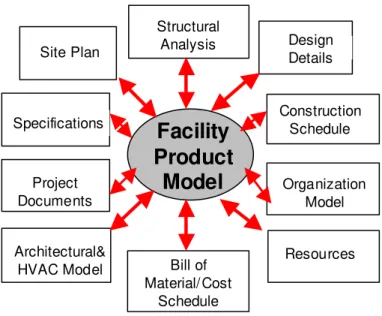
other function-specific software tools. As a result, more project information, representing different discipline-specific aspect models (e.g. specifications, scheduling, estimating, etc.), will be generated and linked back to the model, providing a comprehensive and integrated project data model (Figure 1). The link between the product model and aspect models is typically achieved through defining relationship classes that associate objects in the two models. Eventually, the integrated project model would represent a comprehensive view of the project and bind together the multi-disciplinary aspects of the project information.
Insert Figure 1: A product-centric approach to implement integrated project repositories
The integrated project model would play an important role to ensure the consistency and integrity of project data, enable efficient data sharing and exchange, support tool interoperability, and timely access to project information. The integrated project model would allow the mapping of project information from one view to another and hence allow the exchange of project information between project actors and applications. The integrated model can assist to discover data omissions and inconsistencies, manage dependencies and interactions between different project disciplines, and to communicate project data in an efficient and effective way. By explicitly modeling the relationships between various project entities, the framework can also implement methods to determine whether any interdependent objects need to be updated as a result of changes. Such methods could range from simple techniques to notify parties that might be affected by a change, to more sophisticated techniques to automate change propagation and conflict detection/resolution mechanisms. Multi-disciplinary project teams could also use the integrated project model to assess interactions between different project aspects, to evaluate decisions, and to resolve conflicts.
The integrated project model can also facilitate the subsequent reuse of project information to optimally support the operation and maintenance activities of the facility. The model can also enable facility managers and owners to specify the content and structure of project information that will be handed over at the end of the project, and thus formalizing and systematizing the handover process. Having this information readily accessible in an organized and integrated form will potentially save significant amount of time and resources typically spent to locate, reinterpret, or re-enter this information into facilities management software. Moreover, the same integrated model can continue to
be used through the lifecycle of the facility. For example, changes in a component’s condition, inspection reports, and maintenance records can be used to update the model.
Implementing the product-centric approach in integrated project systems would require the use of AEC standard data models that provide the capability to model various project aspect models (i.e. multi-disciplinary project information) and to provide mechanisms to link this information to the facility product model. The IFC data model, which includes mechanisms to link multi-disciplinary project information and to extend the data model beyond its defined scope, provides a good example of a data model that can efficiently support the product-centric integration approach.
3. A THREE-TIER COMPONENT-BASED FRAMEWORK FOR INTEGRATED PROJECT SYSTEMS
From a software architecture perspective, the complexity and scope of the required framework services necessitates their breakdown into a set of functions that can be performed by various components. A typical component represents a reusable self-contained subsystem that can interact with other components through implementing and publishing a set of interfaces that other components and applications can instantiate and access. Components can be developed, maintained, and deployed independently, which would allow the incremental development and deployment of software systems (Szyperski, 1998). The framework has defined a number of components and organized them in a multi-tier architecture to facilitate the integration of their functionality. Components’ interaction is primarily achieved by accessing interfaces exposed by each component and through the use of the common project data repository.
A multi-tier architecture that separates the functionality between the function-specific applications and the common services components seems particularly suitable to provide the modularity and flexibility required in integrated projects systems (Halfawy and Froese 2002b). Applications provide the functionality to perform specific project activities (e.g. design, scheduling, cost estimating), while components provide common domain-specific functionality (e.g. data and workflow management) needed to integrate and manage project information and processes. Applications access the components’ functionality through published interfaces, and therefore should
make no assumptions about the implementation of these components. Similarly, the framework should make no assumptions about the implementation of individual applications. This separation of functionality and standardization of interfaces provides the flexibility to accommodate future modification, extension, and technology improvement, without the need to significantly modify the framework components.
The framework design does not impose any restrictions on the implementation details of components, and a number of methods and technologies can be employed. Examples of alternative component technologies include CORBA, JavaBeans, COM/DCOM, or .NET. An important requirement of integrated project systems is to allow its components and applications to transparently run in a distributed environment. Most existing component technologies provide mechanisms to enable components and applications to transparently run in a distributed environment, by shielding the details of data marshaling and accessing remote components so that the access can be performed transparently as if the components are running on local machines.
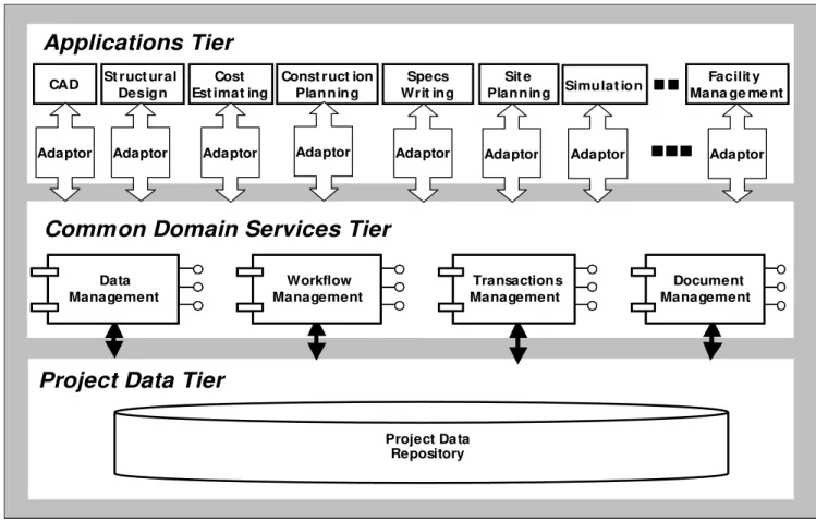
The proposed framework defines three tiers: the applications tier, the common domain services tier, and the project data repository tier (Figure 2). The core functionality of the framework is implemented in the middle-tier common services components. The components have been defined by breaking down the overall required functionality into a set of specific group of services and then mapping the service groups into a set of domain-specific components; each component (or set of components) would provide functionality to support specific class of service. The defined components span four main areas of functionality: data management, document management, transactions management, and workflow management. The following sections will discuss different parts of the framework.
Insert Figure 2: Architecture of the component-based framework for integrated AEC project systems
3.1. The Model-Based Project Repository
The project repository contains the specific project objects’ instances and documents produced and shared by different applications. Primarily, a repository can be implemented in two main forms depending on the required level of data management functionality: using simple neutral files; or using a centralized Database Management System
(DBMS). The repository may also support data access locally or across networks (in a client-server or web-based architecture).
Most existing implementations rely on the application-to-application exchange of neutral files (e.g. STEP Part21 or XML files). However, file-based data exchange is very limited in its scalability and ability to manage a large pool of shared project information or to support the data management functionality required by large AEC projects. Also, sharing project data using neutral files makes it difficult to control or track changes and versions of the data. File exchange is not well suited for large scale project data sharing since it requires exchanging the entire project model despite the fact that an application or project participant would typically require access to a limited view of the integrated project model.
Different modes of data exchange support different data exchange granularity, and, depending on the specific use case, certain levels of data granularity might be more suited than others. Files represent a coarse-grained form of data exchange that would enable applications to access big chunks of data (e.g. an entire project model or an entire aspect model). Given the fact that a full project model will likely be very large, exchanging these models using files is an obvious performance penalty especially when these files are uploaded or downloaded over networks. Fine-grained data access would enable applications to access small pieces of the project model at a time (e.g. records for a specific object). A centralized project database can offer a flexible data exchange mode to support both file and transactional exchange of data. Applications can accordingly optimize their data access performance by specifying the data granularity most suitable to the particular use case.
Limitations of file-based project repositories can be addressed by using a centralized DBMS to implement the project data repository. A centralized DBMS-based project repository is essential to support sharing and exchange of project information while being accessed concurrently by different users and applications. Users and applications can query the DBMS to retrieve the specific objects related to their respective views or disciplines. The DBMS would also enable the implementation of a variety of data management services that are typically required for large-scale integrated project systems. Besides the basic services for ensuring the data integrity, more advanced services such as version management to track data evolution, change management and propagation, concurrency control, security and
authorization, and meta-data services, can also be implemented. The DBMS can also support the use of distributed data sources by adopting distributed or federated database architectures.
3.2. Applications and Adapters
The applications tier integrates a set of, possibly distributed, function-specific software tools that perform various project activities (e.g. CAD, HVAC design, structural design, specifications, scheduling, cost estimating, etc.). Existing legacy applications can be integrated into the framework to share and exchange project data, and access domain-specific services implemented by the framework components.
Applications that can natively support the data model used in the framework (e.g. IFC) will be able to simply plug into the framework. However, applications that do not support the framework’s native data model will require the use of an adapter to perform bi-directional data mapping. Adapters are the means for encapsulating legacy applications into the framework. Depending on the application characteristics, adapters can be developed in several different ways. The framework does not impose restrictions on the implementation details of adapters (e.g. language, technique). An adapter can be implemented as a standalone software or as an add-on to the host application using any language or Application Programming Interface (API) supported by the host application. An adaptor would use the application’s object model to access the internal data model and use the services of the framework’s components to access and exchange data stored at the project repository.
3.3. Data Management Components
The data management components are used by other components and applications in the framework to support data sharing and interoperability through maintaining an interface to the centralized project repository. The implementation details of the data management components will depend on the structure of the project repository. Data management components that only support file-based project repositories will be easier to implement. However, the data management functionality offered will be minimal. To support centralized or distributed project repositories, the data management components should implement more advanced data management functionality using the
services offered by the underlying DBMS (e.g. concurrency control, version management, etc.). The use of DBMS-based project repositories is essential for implementing the data management functionality required by an integrated project system. However, these repositories are not currently in use in the industry and a standardized methodology to implement them needs to be clearly defined.
Creating a DBMS-based repository and data management components is a two-step process. First, the project data model, defined in EXPRESS or XML schema language, should be mapped to a schema supported by the underlying DBMS. Second, the data management functions of the DBMS can then be used to populate, access, query, and manage the project data repository. The schema mapping process was extensively studied, and a number of methods and tools that map EXPRESS data models to relational and object-oriented schemas supported by a number of commercial DBMS were reported (e.g. Halfawy 1998, Loffredo 1998). However, the applications that used these tools had to use the DBMS-specific Data Manipulation Language (DML) to query and manipulate the data, and thus became dependent on the specific DBMS. More recently, a number of implementations have been underway to develop data management components to manage DBMS-based project data repositories and to enable web-based data access and partial exchange and update of the IFC project data. In the literature, these components have been termed as “Model Servers.” Most notable is the effort to develop IFC model servers (Adachi 2006a, EuroSTEP 2006). These model servers supported the functionality to upload/download files, query the IFC model, and create/modify objects.
Achieving interoperability at the components level would necessitate the definition of a standard language or API to communicate between the components and data repository solutions. Using a standard interface, the data management component can support a wide variety of data sources and DBMSs without the need to modify any of the applications or other components that use this interface. Also, applications can transparently access the services of the data management component regardless of the underlying database technology, and thus be independent of the specific database technology. Adopting a standard interface will also ensure that various database vendors may natively support these interfaces in their database systems.
With the recent proliferation of XML tools and standards, many industries, including AEC, are moving to adopt and use XML as an interface standard. By storing STEP data in XML files, application developers can use standard XML processing tools, which are far more available and affordable than EXPRESS processing tools, to manipulate STEP data. An XML-based interface language is expected to become more widely accepted. A number of commercial DBMS already support web-based query and access of the database (e.g. using XML-based version of SQL).
An ongoing effort to unify existing data access methods and define a standard data access language for IFC model servers is the Simple Access to the Building Lifecycle Exchange (SABLE) project (SABLE 2006). SABLE aims to define and implement a standard AEC domain-specific XML-based language to communicate with and to query and manipulate IFC data stored in relational DBMS. Perhaps the next step in such an effort would shift the focus from standardized web-based data access to address various aspects related to the data management functionality (e.g. concurrency control, version control, and change management).
3.4. Document Management Components
Traditionally, AEC project information is stored and exchanged using unstructured, paper or digital, documents. Examples of these documents include design drawings, analysis calculations, bill of materials, specifications, schedules, contracts, etc. With recent proliferation of model-based software tools and standard data models, a large part of this information can now be represented in a neutral model-based format (e.g. STEP P21 or XML files). However, a significant portion of project information is still, and will most likely remain, document-based. Therefore, an approach to integrate documents with object-based models is critical to support project lifecycle information management. The document management component in the framework aims to fulfil this function.
Document management uses a set of document attributes, or metadata, to classify, organize, search, and retrieve documents. The document management component defines metadata attributes to effectively describe the content of a project document, and establish a bi-directional link between these attributes and related objects in the project model, and thus enables context-based access to documents directly from the object model. Besides generic attributes such as document author, date, topic, etc., a document’s metadata should also define project-specific attributes that
would enable easy and efficient search and retrieval of documents pertaining to a specific subject. Although standards exist for defining generic attributes of documents, e.g. (Dublin Core 2006), no standard is available for defining AEC documents metadata and there is an obvious need to define such a standard and implement it in document management components.
Unstructured documents can be externally referenced from objects in the project model. However, simple document referencing has limited integration value since it does not maintain any “active” link between the document and its related object(s). An active link refers to the fact that a link between the data included in the document and the model is maintained and can be used to automatically propagate changes between the model and the document. Achieving an active link would require imposing some structure on the documents (e.g. using forms) and then linking the document “fields” with relevant entities “attributes.” For example, the height of a door defined in the IFC schema using the OverallHeight of IfcDoor object can be linked to the door height field in the door data sheet that is stored as a form.
3.5. Transaction Management Components
A significant amount of the information exchanged in a typical AEC project can be modeled and efficiently communicated in the form of transactions (online or offline). Examples include requesting or querying information from various data sources, exchanging design or construction documents related to a specific project, exchanging data related to a specific business transaction (e.g. purchase orders), or distributing updated information to project teams. Furthermore, accessing online data repositories or data exchange between applications over the Internet would require exchanging data at a fine level of granularity where small chunks of the model data are communicated.
Existing systems that support transactions in the AEC industry are mainly based on the Electronic Data Interchange (EDI) standards. Almeido et al. (1998) reported that there were 28 generic EDI messages that could be used in the construction industry, 12 of which were developed specifically for the construction industry. These messages mainly covered tendering, establishment of contract, materials management, accounting, and drawing administration. In spite of the many research efforts that have been conducted during the past several years to introduce EDI to the
construction industry, very limited success has been achieved (Almeido et al. 1998). Traditionally, the cost of proprietary EDI software and hardware required made it infeasible to many AEC organizations to implement and maintain EDI systems. Moreover, the lack of an industry-wide standard project information model caused EDI applications to be limited to address project processes related to procurement and tendering.
Recently, many AEC organizations have started to use web-enabled software tools, project web portals, and B2B eCommerce transactions. Although these systems enabled better collaboration and information exchange between project teams, and enabled organizations to perform some business processes online, the information is still exchanged in an unstructured ad-hoc format and in a manual and informal manner. These systems lack a consistent model that defines their operation and transactions, and generally do not interoperate with other systems. Achieving interoperability through message communication between various applications and across organizational boundaries has been rarely studied or implemented in the industry. Also, the emergence of industry-wide data repositories such as product catalogues and online libraries has increased the demand to develop common transaction interfaces to enable easy access to these repositories over the Internet. With the expected proliferation of these systems, the need to formalize and standardize transactions protocols becomes even more critical. The emergence of web-based standards and the ongoing efforts to base Electronic Data Interchange (EDI) systems on XML as well as the emergence of mature standard AEC data models are expected to make the use of electronic data transactions more common in the near future.
The transaction management component aims to support the exchange of transactions between the framework components and applications and other online software systems running within or without the organization. This exchange may be automated or user-initiated. The transactions management component enables the applications to interoperate with online data consumers or providers, especially across different organizations, via the use of message-based protocols. This component will need to define and implement transactions in a way that is consistent with existing standard data models, and emerging web interoperability standards such as XML SOAP and web services. A methodology for defining standard transactions protocols was developed but has yet to be fully tested and implemented (Halfawy et al. 2002b).
3.6. Workflow Management Components
Interdependencies between project processes necessitate the definition of rules and procedures to manage and coordinate the information flow and the workflow within the project. The workflow management component defines methods to support modeling and implementation of these rules and procedures in the framework. A substantial body of knowledge that can support the analysis and modeling of the workflow of AEC project processes is currently available (e.g. Levitt et al 1996, WfMc 2006). Workflow models would help to provide an integrated view of different project roles, software tools, information requirement and flow, and project processes, and to identify the interfaces between these processes. The components would implement functions to enable automatic routing and tracking of project documents and to support the collaboration of geographically distributed project participants.
4. IMPLEMENTATION OF A PROTOTYPE INTEGRATED PROJECT SYSTEM
Implementing the proposed framework in a particular AEC domain has two main prerequisites: availability of a project data model that can support modeling and integration of various project aspects (preferably an industry-wide standard); and availability of a set of software applications to support various project activities. Transforming the framework into an actual software implementation involves further refinement of the architecture and taking into consideration a number of factors related to the project organization, available technologies, and suitable modes of data sharing, etc. Obviously, no single implementation would satisfy the requirements of every project and any solution should be developed to provide a flexible and customizable environment that could be adapted to accommodate different project scenarios.
An ideal implementation of an integrated project system would support the exchange and management of different forms of project data (i.e. object models, documents, and transactions). However, project organizations or the technology available to an organization may dictate or limit the possible forms and modes of data exchange. For example, organizations may not be able to share and maintain a centralized DBMS-based project repository, and therefore should share data through files.
The prototype software was developed to support building design and construction projects. The prototype used the IFC 2x data model to represent the integrated project schema. A set of middle-tier components were implemented using Microsoft COM/DCOM technology and programmed using Visual C++ and Visual Basic languages.
4.1. Implementing the Project Repository and Framework Components
The project repository was implemented to support file-based data exchange, primarily using STEP Part 21 Physical Files (SPF) or XML files formatted using the BLIS XML schema (BLIS 2006). The data management components maintain the IFC project repository and enable other components and applications to interface with the project data repository that contains persistent IFC objects. Applications can import/export project data using the standard IFC data model schema. The data management components supported mapping of project information from one view (or discipline) to another and hence allow the exchange of project information between multi-disciplinary project actors. Figure 3 provides an overview of the implemented project repository, data management components, applications, and adapters.
Figure 3: An overview of the implemented data management components, applications, and adapters
The data management components supported mapping of IFC project data between a wide range of data sources such as relational database management systems, through the use of the standard Open Database Connectivity (ODBC) or Active Data Object (ADO) interfaces, and XML files, through the use of the XML DOM interface. The components also supported transparent access to local or remote data sources. The data management components used the IFCsvr COM component (Adachi 2006b) to parse, access, and create IFC files. The IFCsvr provides methods to access and manipulate IFC data stored in standard STEP Part 21 or XML files.
The data management components defined a unified COM API interface, called JsServer, to enable consistent and standardized access to the functionality of the components and to isolate the applications from the details of the underlying data sources. Using the standard JsServer interface, the data management components can scale up to
support more variety of project data sources without the need to modify any of the applications or other components that use this interface. Also, applications can transparently access the services of the data management component regardless of the structure or format of the data sources. The JsServer interface enabled various applications, adapters, and other framework components to communicate with and to query and manipulate the IFC data stored in the project repository. In a sense, the JsServer interface is similar to the SOAP-based SABLE interface defined in the SABLE project (SABLE 2006).
The document management component was implemented to support managing and maintaining a database of project documents. Documents are described with a set of metadata attributes where users could query and retrieve documents from the repository based on the predefined set of metadata. Project documents are externally referenced from objects in the IFC project model. Documents are associated with IFC objects using the IfcDocumentReference entities. For example, an IFC wall object can reference the document that specifies the style, material, or characteristics of the wall. However, the IFC schema does not support the definition and assignment of attributes (in the form of property sets) to an instance of IfcDocumentReference or IfcDocumentType since these entities are not derived from IfcObject. As a result, encoding document metadata attributes as property sets is not possible in the current IFC data model.
The transactions management component implemented the functionality to receive and send messages to access and query the IFC project repository via a SOAP-based web service. Other components and applications use the services of this component to communicate with online systems either within or across organizational boundaries. The component is intended to support a set of pre-defined transactions that can be used to exchange information or to retrieve information from online data sources in the form of messages. At this stage, the transaction management component supported accessing and querying IFC data files. The component’s interface was implemented as a SOAP-based web service. Applications can request the service to load a specific IFC file, and then manipulate the IFC objects data in the files using a set of service operations. For example, applications can request the retrieval of all or a specific wall object. The component functionality is currently being extended by defining and implementing other protocols such as a “Request Quote” scenario, where a designer requests quotes from a number of suppliers. Based on that protocol, the designer passes a set of wall objects; each has a property set that describes the design
requirements. This transaction is automatically processed by a web service running at the supplier site and as a result, a complete product specification and a quote are sent back to the designer. After evaluating these quotes, the designer makes a decision and the winning supplier will receive a “Purchase Order” transaction from the designer.
In the implementation of the workflow management components, a number of common workflow models have been identified, analyzed, formalized, and modeled. (Pouria et al. 2002) presented these models for two scenarios: a document review process and a material delivery processes. The models are represented using UML activity, swimlane, and sequences diagrams. The models demonstrated the interaction sequences of information flow between project roles, software applications, conditional logic, and start/end states. More workflow models are being developed to address change management, request for quote, procurement, and request and update of design and schedule information.
4.2. Implementing Applications and Adapters.
The applications tier integrated a number of function-specific software tools to extend the functions provided by the framework into specific project domains. The applications were selected to support architectural design (Architectural Desktop, ADT), construction scheduling (Microsoft Project), and cost estimating (Timberline Precision Estimating). Although some of these applications support a model-based approach, the models are application-specific and do not support the standard IFC 2x data model. Therefore, adapters were developed to perform the mapping of the internal representation of the project data in these applications to and from the IFC 2x schema. Two other applications were developed to support specifications writing and 4D project simulation. These two applications directly supported the IFC schema and therefore, no adapters were needed (Figure 3).
A common issue with almost all adapters is that the number of attributes of a particular object represented using a function-specific application will be much more than the number of attributes defined for a corresponding IFC entity. Although this might seem as a limitation in the IFC schema, our experience with the prototype showed that the mapping of common attributes was sufficient for the purposes of integration and data exchange between various project domains. It is worth noting that the IFC schema was not intended to represent all possible attributes for a
particular object. Rather, IFC was primarily intended as a core model that supports the common overlapping area between various project disciplines in order to facilitate easy integration and data exchange. However, in order to maintain consistency in bi-directional data exchange and enable better data management between different sessions, a mechanism that links an IFC instance with its application-specific counterpart needs to be established and implemented in the adapter. In many existing adapters where data is exchanged, or translated, from the application’s data model to IFC in a uni-directional manner, this issue is not addressed. However, to enable bi-directional data exchange and the use of the IFC data model at various stages of the project lifecycle where data exchange will need to be performed in several sessions, this mechanism is needed. In our implementation, the adapters mapped the Globally Unique Identifier (GUID) of IFC instances onto an application-specific user-defined attribute of the corresponding object. When data were imported or exported, the adapter uses this information to detect if a particular object was added, deleted, or modified. The user is provided with a list of detected changes and given the option to accept, reject, or override changes. Consequently, an application’s internal data and the corresponding IFC file are kept synchronized.
4.2.1 Architectural Desktop Adapter
The Architectural Desktop (ADT) adapter was developed using the Object ARX class library (Autodesk 1999). The adapter added a menu interface in ADT where different data mapping functions could be accessed. Users can import an IFC file where the adapter maps the IFC objects to the corresponding ADT entities. Almost all IFC architectural design entities have corresponding ADT objects. For example, an IfcWall object can be easily mapped from and to an AecWall entity where the wall dimensions are extracted from the IfcWall geometric representation attributes and used to create the ADT wall object.
4.2.2 Microsoft Project Adapter
The Microsoft Project adapter was implemented as a COM add-in that added a menu interface to the application where data mapping functions can be accessed. A standalone and a web-based version of the adapter were also developed. The adapter maps the application entities to IFC entities as follows:
• Each Task is mapped to IfcTask
• Task schedule times are mapped to IfcScheduleTimeControl • The project is mapped to IfcWorkSchedule
• Tasks are assigned to the schedule using an instance of IfcRelAssignsTasks for each task • Task nesting is mapped using the IfcRelNests
• Each Resource is mapped to IfcResource (IfcCrewResource or IfcConstructionMaterialResource) • Precedence relationships are mapped using IfcRelSequence
• Resource assignments are mapped using IfcRelUsesResource
• An instance of IfcProject is created and the IfcScheduleTimeControl is assigned to the project using an instance of IfcRelAssignsToControl
Construction tasks (IfcTask entities) are (manually) linked to facility products (IfcBuildingElement entities) by defining IfcRelAssignsToProcess entities where the RelatedObjects attribute references the instance of IfcBuildingElement and the RelatingProcess attribute references the related IfcTask entity. Linking products and tasks enables users to easily access tasks related to a specific product, and to retrieve all products related to a specific task. It also enables the 4D visual simulation of the construction sequence and to view the projected status at any point during the construction process. 4D simulation could provide construction planners with an insight into the construction process to identify potential conflicts and evaluate the interaction between various activities.
4.2.3 Timberline Precision Estimating Adapter
An adapter was developed to access Precision’s cost estimating database. The adapter was implemented as standalone software that accesses the cost estimating database using Timberline’s ODBC driver and Microsoft Active Data Objects (ADO) classes. The adapter maps the entities of a Precision cost estimate to IFC entities as follows:
• The estimate is mapped to an instance of IfcCostSchedule
• The IfcCostSchedule is assigned to the IfcProject entity using an instance of IfcRelControls • Each cost item is mapped to IfcCostElement
• Each assembly is mapped to an instance of IfcCostElement that nests other IfcCostElement entities using an instance of IfcRelNestsCostElements
Although IFC’s cost estimating classes are not as rich as the scheduling classes, many cost-related data can be modeled and integrated using the IFC schema. Cost items and assemblies (IfcCost entities) can be linked to facility products (IfcBuildingElement entities) by defining IfcRelCostsObjects entities where the RelatingControl attribute references an instance of IfcCost and the RelatedObjects attribute references the related instance of IfcBuildingElement. Linking products and costs enables users to access cost items related to a specific product, and to find all products that relate to a specific cost item. It also enables easy calculation of the cost of any particular product. Another benefit of this integration is the ability to automatically calculate materials quantities from product models and to map these values to the cost element attributes. Cost element’s quantities related to other cost categories (e.g. labour, subcontractor, etc.) can be derived from the product materials quantity. IFCs currently do not support some important aspects of the cost estimating process, in particular the definition of multiple cost categories per cost element, and the support of parametric estimating where variables and formulae are used for takeoff and estimating of parametric assemblies and cost elements.
4.2.4 4D Application
The 4D application uses the links between the schedule’s IfcTask entities and the product model’s IfcBuildingElement entities to create a visual simulation of the sequence of the construction process over time. The application allows the users to specify the start and end time of simulation, and to stop the simulation at any moment to walk through the project site. This tool proved to be useful in assisting the project actors to identify potential conflicts and evaluate the interaction between various activities.
4.2.5 Project and Product Specifications Application
The specifications application supports the development of project and products specifications. Specifications are typically prepared as a separate set of documents with no direct or explicit links with the project object model. As a
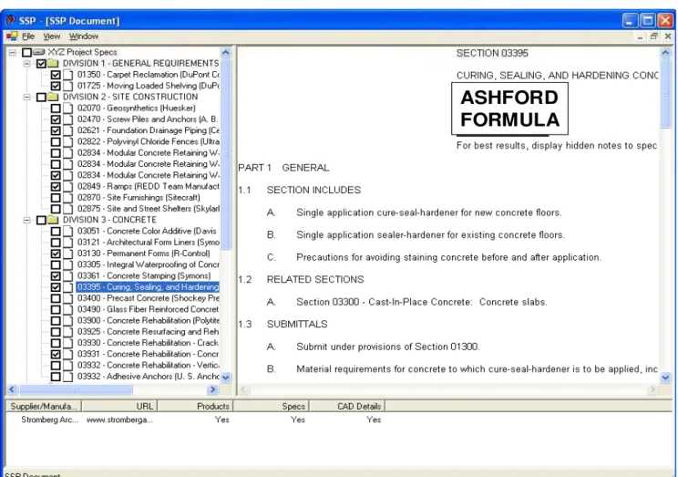
result, inconsistencies and errors due to discrepancy between design and specifications are commonplace in many projects. The application used the ARCAT (ARCAT 2006) MasterFormat-based specifications where different sections are stored as separate files. Using a tree-based interface that resembles the MasterFormat hierarchy (Figure 4), users select and edit relevant sections and then link the resulting sections specifications to the IFC objects as external document references using instances of IfcDocumentReference.
Insert Figure 4: A screenshot of the specifications authoring application
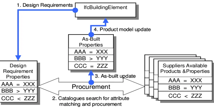
Users can access databases of products and suppliers in order to select and specify the most suitable products that meet the project requirements. A product specification is described as attribute-value pairs that are represented using a property set. The property sets are linked to any number of instances of IfcBuildingElement of the product model using instances of IfcRelAssignsProperties. Also, documents and data sheets related to a specific product can be referenced by using instances of IfcDocumentReference. Therefore, specifications related to any product can be simply accessed from the facility product model. Figure 5 describes a four-step workflow process to specify, select, procure, and update the project model.
Insert Figure 5: Four-step workflow process for product selection and procurement
Standardizing the representation of products’ attributes or property sets for a particular class of products will further enable the implementation of standardized and efficient methods to automatically search for and select appropriate products that would potentially satisfy the design requirements. Product search and selection functions could access remote suppliers’ databases to match the list of design requirements (specified in the product’s property set) with the properties of products in the suppliers’ databases. After deciding on a particular product that best meets the design requirements, the procurement process can be largely automated. Once the products are procured and constructed, the as-built project information and the project data repository can be automatically updated to reflect the specifications of these products.
4.3. Example System Use
The following scenario illustrates a typical use of the prototype system. First, a preliminary architectural design is developed and a number of IFC design objects are defined. The CAD software generates an IFC model and exports the design data into a standard IFC STEP part 21 file which is added to the project repository. Cost estimating and scheduling software import the design data, generate more IFC-based project (process, schedule, and cost) information, and link this information back with the project model that was initially used. The project repository will integrate the different project aspects and maintain the relationships between the IFC objects (e.g. linking cost and schedule data to building elements). Project actors from different disciplines can access the integrated project model to assess interactions and dependencies between various project activities, and resolve conflicts and inconsistencies.
The prototype enables users to manage and navigate through project information using a tree-like “project explorer” interface. This interface represents project views in a hierarchical tree structure and employs the services provided by the data management component to access various pieces of project information: the facility product model, resources, schedule, cost estimate, specifications, and documents (Figure 6). Making various aspects of project information accessible from a single model significantly improves the flow of information across various project disciplines. The project explorer enables users to link related project objects by a simple drag-and-drop operation. For example, dragging an activity from the construction schedule and dropping it onto a building element automatically creates an IfcRelProcessOperatesOn entity that associates the activity with the building element, and dragging a document node and dropping it onto an IFC object automatically creates an IfcDocumentReference entity that associates the document with the object.
Insert Figure 6: Using the project explorer interface to access the integrated project model
5. CONCLUSIONS AND FUTURE DIRECTIONS
Data and process integration has long been recognized as the key to increased productivity and improved quality of AEC projects. The AEC industry is clearly undergoing a paradigm shift and becoming more focused on the
integrated multi-disciplinary project aspects. Accordingly, the need to develop and deploy comprehensive software systems that can support this integration has become evident. The objectives of this integration can hardly be realized without the use of integrated and interoperable systems. After many years of research and development, the AEC industry has now started to embrace and adopt software systems that support and promote concepts of integration and interoperability.
This paper presented an attempt to define a framework based on standard object-based project data models, to facilitate the implementation of integrated project systems. The framework defined methods that can potentially improve the availability, consistency, and integration of project information and processes. In light of the proposed framework model, a number of future directions can be identified. Most importantly, we will need to focus our efforts on defining and developing generic domain-specific standardized components that can make the development of interoperable and integrated project systems more feasible and economic. Systems developers will be using component libraries in order to access generic and standardized domain functionality. We also need to develop standardized protocols and approaches to support the document and transaction management procedures in a way that is consistent with the object-based data management. Developing standard data models in AEC domains should become a priority in the coming years in order to support the implementation of integrated project systems. Successful development and implementation of IFC and CIS/2 should be a catalyst for other domains to develop similar models, probably following similar methodology.
In addition to the need to more thoroughly address the many research issues highlighted by the framework, we can identify some industry-oriented research activities that would potentially lead to improving the framework. Field studies are needed to assess the impact of implementing integrated project systems and how they could impact the organization structure, team interaction, communication, and productivity of project teams. We also need to conduct studies to evaluate the costs and benefits of fully implementing and introducing these systems into actual operation.
The authors gratefully acknowledge support from the Natural Sciences and Engineering Research Council of Canada, Collaborative Research Opportunities Program.
7. REFERENCES
Adachi, Y. (2006a). “IFC Model Server Development Project.” <http://cic.vtt.fi/projects/ifcsvr/> (Dec. 14, 2006). Adachi, Y. (2006b). “IFC ActiveX Component.”<http://cic.vtt.fi/projects/ifcsvr/ifcsvrr200/default.html> (Dec. 14,
2006).
Almeido, L, Grilo, A., Rabe, L., Duin, H. (1998). “Implementing EDI and STEP in the construction industry.” Proc., Product and Process Modeling in the Building Industry, ECPPM’98.
ARCAT. (2006). “ARCAT Web Portal.” <http://www.arcat.com> (Dec. 14, 2006). Autodesk Inc. (1999). “ObjectARX Developer’s Guide.”
BLIS. (2006). “Building Lifecycle Interoperable Software.” <http://www.blis-project.org> (Dec. 14, 2006).
Bjork, B. (1994). “Conceptual Models of Product, Project, and Document Data: Essential Ingredients of CIS,” Proc. of Computing in Civil Engineering Conference, Washington, D.C.
Bjork, B. (1994). “RATAS Project- Developing an Infrastructure for Computer-Integrated Construction,” ASCE J. Computing in Civil Engineering, 8(4), pp. 401-419.
Bjork, B. and Penttila, H. (1989). “A Scenario for the Development and Implementation of a Building Product Model Standard,” J. Advances in Engineering Software, Vol. 11, No. 4, pp. 176-186.
Brown, A., Rezgui, Y., Cooper, G., Yip, J., and Brandon, P. (1996). “Promoting Computer Integrated Construction Through the Use of Distribution Technology,” J. of ITCON, Vol. 1, pp.51-67, <
http://www.itcon.org/1996/3/paper.pdf> (Dec. 14, 2006).
CIS/2. (2006). “CIMSteel Integration Standards,” <http://www.cis2.org/> (Dec. 14, 2006).
Dublin Core. (2006). “The Dublin Core Metadata Initiative.” <http://dublincore.org/> (Dec. 14, 2006).
Eastman, C.M. (1999). Building Product Models: Computer Environments Supporting Design and Construction, CRC Press, Boca Raton FL.
Faraj, I. and Alshawi, M. (1999). “A Modularised Integrated Computer Environment for the Construction Industry: SPACE,” J. of ITCON, Vol. 4, pp. 37-52, <http://www.itcon.org/1999/3/paper.pdf> (Dec. 14, 2006). FIATECH. (2006). “Capital Projects Technology Roadmap Initiative.”
<http://www.fiatech.org/projects/roadmap/cptri.htm > (Dec. 14, 2006).
Froese, T., Fischer, M., Grobler, F., Ritzenthaler, J., Yu, K., Sutherland, S., Staub, S., Akinci, B., Akbas, R., Koo, B., Barron, A., Kunz, J. (1999). "Industry Foundation Classes For Project Management—A Trial
Implementation." J. of ITCON, Vol. 4, pp.17-36, <http://itcon.org/1999/2/> (Dec. 14, 2006).
Froese, T., Yu, K., Liston, K., Fischer, M. (2000). “System Architectures for AEC Interoperability,” Proc., Construction Information Technology (CIT), Reykjavik, Iceland, Vol.1, pp.362-373.
Froese, T. (2002). “Final Programme Evaluation Report- Vera – Information Networking in the Construction Process”, <http://cic.vtt.fi/vera/Documents/Froese_Final_VERA_Evaluation_020926.pdf> (Dec. 14, 2006). Froese, T. (2003). “Future directions for IFC-based interoperability.” J. of ITCON , Vol. 8, pg. 231-246,
<http://www.itcon.org/2003/17> (Dec. 14, 2006).
Gallaher, Michael P., O’Connor, Alan C., Dettbarn, John L. Jr., and Gilday, Linda T. (2004). “Cost Analysis of Inadequate Interoperability in the U.S. Capital Facilities Industry,” U.S. Department of Commerce Technology Administration, National Institute of Standards and Technology, NIST GCR 04-867, <http://www.bfrl.nist.gov/oae/publications/gcrs/04867.pdf> (Dec. 14, 2006).
Halfawy, M.R. (1998). “A Multi-Agent Collaborative Framework for Concurrent Design of Constructed Facilities,” Ph.D. Dissertation, Department of Civil and Environmental Engineering and Geodetic Science, the Ohio State University.
Halfawy, M.R., and Froese, T. (2005). "Integration of data and processes of AEC projects using the industry foundation classes," Proc., 6th CSCE Construction Specialty Conference, Toronto, Ontario.
Halfawy, M., and Froese, T. (2002a). “A Model-Based Approach for Implementing Integrated Project Systems.” Proc., 9th International Conference on Computing in Civil and Building Engineering, Taipei, Taiwan, Vol. 2. pp. 1003-1008.
Halfawy, M., and Froese, T. (2002b). “A Component-Based Framework for Integrated AEC/FM Project Systems.” Proc., CSCE Conference of the Canadian Society for Civil Engineers, Montreal, Canada.
Halfawy, M., Hadipriono, F., Duane, J., Larew, R. Froese, T. (2002a). “Developing A STEP-Based Core Information Model For Bridges.” Proc., 6th International Conference on Short and Medium Span Bridges, Vancouver, BC, Canada.
Halfawy, M., Pouria, A. Froese, T. (2002b). “Developing Message-Based Interoperability Protocols for Distributed AEC/FM Systems.” Proc., CIB W78 Conference, Aarhus, Denmark.
Halfawy, M.R., Froese, T.M.; Vanier, D.J.; Kyle, B.R. (2004). “An Integration approach for developing AEC/FM total project systems.” Proc., CIB 2004 Triennial Congress, Toronto, Ontario.
IAI. (2006). “International Alliance for Interoperability, Industry Foundation Classes – IFC 2x. On-line documentation.” <http://www.iai-international.org> (Dec. 14, 2006).
ISO10303. (1992). “Product Data Representation and Exchange, Part 11: Description Methods: The EXPRESS Language Reference Manual, ISO TC 184/SC4.
ISO10303-225. (2006). “Industrial automation systems and integration -- Product data representation and exchange -- Part 225: Application protocol: Building elements using explicit shape representation,”
<http://www.haspar.de/Ap225/> (Dec. 14, 2006).
Kreikemeier, K. (1996). “Design-Build: A Concept Whose Time Has Come..Again,” Construction Business Review, March/April 1996, pp. 40-42.
Kunz, J., Clayton, M., and Fischer, M., (1994). “Circle Integration,” Proc., ASCE Computing in Civil Engineering
Conference, Washington, D.C.
Levitt, R., Cohen, P., Kunz, J., Nass, C., Christiansen, T., and Jin, Y. (1996). “The Virtual Design Team,” Proc.,
ASCE Computing in Civil Engineering, Anaheim, California.
Loffredo, D. (1998). “Efficient Database Implementation of EXPRESS Information Models.” PhD Thesis, Rensselaer Polytechnic Institute, Troy, New York.
PCSC. (2006). “Precast Concrete Software Consortium,” <http://dcom.arch.gatech.edu/pci2/> (Dec. 14, 2006).
Pouria, A., Halfawy, M. Froese, T. (2002). “Developing AEC/FM Transaction Standards,” Proc., 3rd International Conference on Concurrent Engineering in Construction, University of California at Berkeley, California, USA.
SABLE. (2006). “Simple Access to the Building Lifecycle Exchange,” <http://www.blis-project.org/~sable/> (Dec. 14, 2006).
Szyperski, Clemens (1998). Component Software: Beyond Object-Oriented Programming, ACM Press, New York, Addison-Wesley.
Teicholz, P., and Fischer, M. (1994). “Strategy for Computer-Integrated Construction Technology,” ASCE J. of Construction Engineering and Management, Vol. 120, No. 1.
Tracz, W. (1994). “Domain-Specific Software Architecture (DSSA)- Frequently Asked Questions.” Software Engineering Notes, ACM-SIGSOFT, Vol. 19, No. 2.
VERA. (2006). “Information Networking in the Construction Process.” <http://cic.vtt.fi/vera/index.htm> (Dec. 14, 2006).
VTT. (2006). “The Technical Research Centre of Finland,” <http://cic.vtt.fi/projects/index.html>(Dec. 14, 2006).
List of Figures
Figure 1: A product-centric approach to implement integrated project repositories
Figure 2: Architecture of the component-based framework for integrated AEC project systems Figure 3: An overview of the implemented data management components, applications, and adapters Figure 4: A screenshot of the specifications authoring application
Figure 5: Four-step workflow process for product selection and procurement Figure 6: Using the project explorer interface to access the integrated project mode
Facility
Product
Model
Structural Analysis Construction Schedule Site Plan Specifications Project Documents Architectural&HVAC Model Bill of
Material/ Cost Schedule Organization Model Design Details Resources
Facility
Product
Model
Structural Analysis Construction Schedule Site Plan Specifications Project Documents Architectural&HVAC Model Bill of
Material/ Cost Schedule Organization Model Design Details Resources