A COMPARATIVE ANALYSIS
OF AREA NAVIGATION SYSTEMS
FOR GENERAL AVIATION
Steven M. Dodge
June 1973
A COMPARATIVE ANALYSIS OF AREA NAVIGATION SYSTEMS FOR GENERAL AVIATION
by
Stephen Malcolm Dodge
S.B., Massachusetts Institute of Technology 1969
SUBMITTED IN PARTIAL FULFILLMENT OF THE REQUIREMENTS FOR THE DEGREE OF
MASTER OF SCIENCE at the
MASSACHUSETTS INSTITUTE OF TECHNOLOGY June, 1973
Signature of Author...
I
Department of Aerona ics and Astronautics May ll, 1973 Certified by... Certified by.... Accepted by.. Thesis Supervisor(7)
ThPs s SupervisorChairman,\Depar ental Committee on Gduate Students
A COMPARATIVE ANALYSIS OF AREA NAVIGATION SYSTEMS FOR GENERAL AVIATION
by
Stephen Malcolm Dodge
Submitted to the Department of Aeronautics and Astronautics on June, 1973 in partial fulfillment of the requirements for the degree of Master of Science
ABSTRACT
Within the next decade area navigation is to become the primary method of air navigation within the United States. There are numerous radionavigation systems that offer the capabilities of area navigation to general aviation opera-tions. In this analysis the author investigates three such systems: (1) the VORTAC system; (2) the Loran-C system; and (3) the Differential Omega sys-tem. The initial analyses are directed toward a comparison of the systems with respect to their compliance to specified performance parameters and to the cost-effectiveness of each system in relation to those specifications. Further analyses lead to the development of system cost sensitivity charts, and the employment of these charts allows conclusions to be drawn relative to the cost-effectiveness of the candidate navigation systems.
Thesis Supervisor: Walter M. Hollister Title: Associate Professor
ACKNOWLEDGMENT
The author would like to acknowledge the help of every individual who contributed to the research, analysis, and preparation of this work, and he hopes that each of them will accept this general extension of gratitude. There are a few individuals whose contributions were outstanding, and the author would like to acknowledge them individually. Mr. Bill Mace, as contract supervisor of the Tri- University Program for the National Aeronautics and Space Administration, provided the guidance and supervised the sponsorship of this research. Mr. Ted Rhyne contributed a great deal of aid during the Loran-C and Differential Omega investigations and was always extremely pleasant and informative on every contact. Mr. and Mrs. Jack Howell provided a quiet place to work and a great deal of psy-chological support when it was necessary, and I am most grateful to them. Pro-fessor Robert W. Simpson was one of the thesis supervisors and constantly pro-vided a stimulating forum for the research and analysis. And finally, Professor Walter M. Hollister supervised the complete effort and through his patience, understanding, and active participation guided it along to its completion.
Finally, thanks must go out to the National Aeronautics and Space Adminis-tration for supporting the research through NASA Grant NGL 22-009-640, "Joint University Research Program for Air Transportation Needs".
TABLE OF CONTENTS
Chapter
1 AREA NAVIGATION AND ITS APPLICATION TO
GENERAL AVIATION . . . . 1.1 Introduction . . . .. . . .. . .. . . . .. . . ..
1.2 The Benefits of Area Navigation ...
1. 3 Specification of Operational Requirements ...
1.4 The Cost-Effectiveness Assessment . . . . 2 THE VORTAC SYSTEM OF RADIONAVIGATION. . . . .
2. 1 The Very High Frequency Omnidirectional Range ... ...
2. 1. 1 Conventional VOR Transmitter Operation . . . .
2.1.2 VOR Receiver Operation . . . . 2.1.3 VOR Accuracy Capability . . . .
2. 1.4 VOR System Improvements . . . 2.1.4.1 Doppler VOR . . . .
2.1.4.2 Precision VOR . . .
2. 1. 4. 3 Antenna System Improvements . . . .
2.2 Distance Measuring Equipment . . .. . .
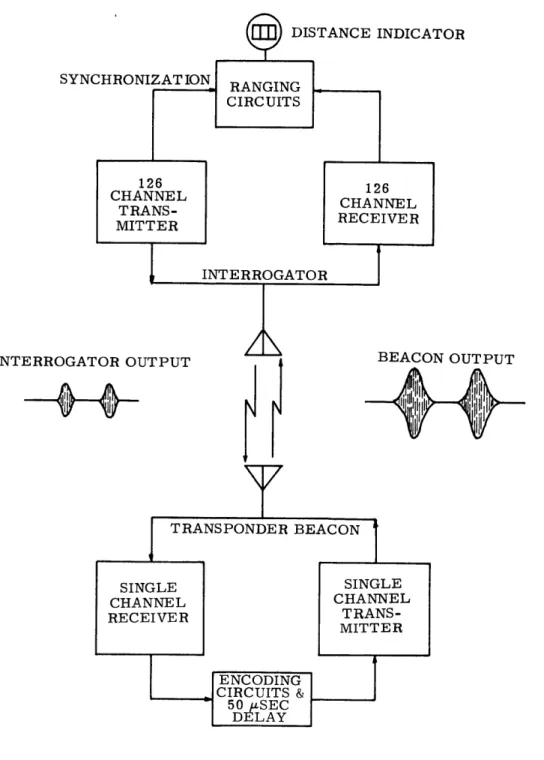
2.2. 1 General Method of Operation . . 2. 2.2 The Airborne Interrogator. . . .
2.2. 3 The Ground Transponder Beacon 2.2.4 DME System Operation and Its
Future Potential . . . .
2. 3 VORTAC Area Navigation Operations . . 2.4 VORTAC Performance . . . . 2.4.1 System Accuracy . . . . 2.4.2 Coverage.... ... 2. 4. 3 Availability of Signal . . . . Page 10 10 13 14 16 . . . . . . . . . 52 . . . . 55 . . . . 59 . . . . 59 . ... 69 . . . . 73
TABLE OF CONTENTS (Cont.)
Chapter
2. 5 Implementation Plans/Costs of the System. . . . .
3 THE LORAN-C RADIONAVIGATION SYSTEM . . . .
3. 1 Low Frequency Propagation . . . .
3.2 Pulsing of Loran-C Signals . . . .
3. 3 Loran-C Position Fixing: Time Difference . . . . 3. 4 Loran-C Transmitter Characteristics . . . .
3. 5 Loran-C Receiver Characteristics . . . .
3.6 Loran-C Performance . . . .. ... 3. 6. 1 System Accuracy . . . . 3.6.2 Coverage.. . . . . ... .. ... .. . .. 3. 6.3 Availability of Signal . . . .
3. 6. 4 Additional Capabilities . . . . 3.7 Implementation Plans/Costs of the System. . . . . 4 THE OMEGA RADIONAVIGATION SYSTEM . . . .
4. 1 Omega Continuous Wave Transmissions . . 4. 1. 1 Phase Difference Measurements .
4.1.2 Omega Lane Ambiguity . . . . 4.1.3 Omega Signal Format . . . . 4.2 Very Low Frequency Propagation . . . . .
4. 3 Differential Omega . . . . 4. 4 Omega Receiver Characteristics . . . . 4. 5 Differential Omega Performance . . . . 4. 5.1 System Accuracy . . . . 4.5.2 Coverage.... ...
4. 5. 3 Availability of Signal . . . .
4. 5. 4 Additional Capabilities . . . .
4.6 Implementation Plans/Costs of the System.
5 A COMPARATIVE ANALYSIS OF CANDIDATE
AREA NAVIGATION SYSTEMS . . . .
5. 1 5.2
Navigation System Error Budget . . . .. .
Comparative System Analysis for Specified Operational Performance . . . . . . . . 120 .121 . . . . 124 . . . 128 . . . . 130 . . . . 135 . . . . 136 . . . . . 139 . . . . 139 ... 142 . . . . 144 . . . . . 145 . . . . 146 151 152 154 Page 77 88 88 92 97 100 102 105 105 113 113 114 115 120
TABLE OF CONTENTS (Cont.)
Chapter Page
5. 3 Sensitivity Analyses of the Radionavigation System Cost Elements to Changes in
Perfor-mance Specification . . . . 159
6 CONCLUSIONS . . . . 172
REFERENCES . . . . 174
LIST OF FIGURES
Figure Page
1-1 Improvement to Route Directivity as a Result of Area
Navigation Capability . . . . 12
2-1 VORTAC Operation . . . . 19
2-2 VOR Variable Signal Cardioid . . . . 23
2-3 Phase Relationship Between VOR REF and VAR at the Cardinal Compass Points . . . . 24
2-4 Orientation of the Four Alford Loops in the VOR Antenna System . . . .. . . . .. 27
2-5 Radiation Patterns from the Alford Loop Pairs in the VOR Antenna System . . .. . . . . 28
2-6 Resultant Figure 8 Radiation Pattern for All Alford Loops Having Equal Power Input . . . .. . . . . 29
2-7 Formation of Cardioid Shaped Composite Radiation Pattern in the VOR System . . . .. . . . . 31
2-8 Schematic Drawing of Conventional VOR Transmitter . . . . 32
2-9 Schematic Drawing of Conventional VOR Receiver . . . . 33
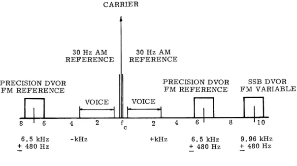
2-10 Spectrum of Single Sideband Doppler VOR with Precision FM Reference . . . . .. ... . . . .. 42
2-11 DME Operational Principle. . . . -. 45
2-12 DME Pulse Parameters . . . .. 49
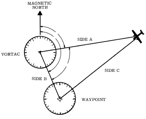
2-13 VORTAC Position Fix . . . - 56
2-14 Navigation Triangle for VORTAC Area Navigation . . . .. . . 58
2-15 Determination of Cross-Track Deviation . . . .. 60
2-16 Position Error vs Separation Distance for Conventional and Post-1982 VORs . . . . . .. . .. . . . . . . . . 62
2-17 Slant Range Error . . . .. . . . . 63
2-18 Displacement Errors for VOR Configurations . . . . 65
2-19 DME System Errors . . . .. . . . ..67
2-20 Combined VORTAC Radionavigation System Error . . .. . .... 68
2-21 VHF/UHF Radio Horizon . . .. . . . .. . . . .... 70
LIST OF FIGURES (Cont.)
Figure Page
2-23 Circular Coverage Situation . . . . 82
2-24 Circular Overlap Phenomenon . . . . 82
3-1 Low Frequency Propagation Paths . . . . 89
3-2 Relative Field Intensities of the Groundwave and Various Modes of the Skywave as the Range Changes . . . . 91
3-3 Variation of the Skywave Delay with Distance for Different Ionosphere Heights . . . . . ... .. 91
3-4 Signal Detected at the Receiver for a Single Pulse Transmission . . . .. . . . .. o. . . . .. . . . . . 93
3-5 Loran-C Format for U. S. East Coast Chain. . .. .. .. . . . .. 96
3-6 The Principle of Position Fixing by the Loran-C System . ... .. 99
3-7 Two Time Differences Determine the Position of the Aircraft... ... - - - . 101
3-8 Loran-C Transmission Pulse . . .. . . . . .. ... .. 101
3-9 Operation of a Loran-C Receiver . . . ... . . . . 104
3-10 Effect of Hyperbolic Divergence . . . ... . .. .. . ... .. . 108
3-11 Nomogram for Computing Contours of Constant Geometrical Accuracy . .. . .. . . . , . . . . . . 110
3-12 Example Problem: Use of Nomogram . . .. . . . .. . . 111
3-13 Contours of Constant GDOP Multiplier. .. .. ... o. . .. 112
3-14 Proposed Loran-C Coverage of U. S. Coast Guard Implementation Program . . . .. . . . .. .. . . . 116
3-15 Proposed Loran-C System for Complete Coverage of Conterminous United States and Alaska . . . .. .. . . . . . 118
4-1 Continuous Wave Signal . . . . . . . . . . . . 122
4-2 Circular Lines of Position ... 123
4-3 Omega Family of Contours . . .. . . . . . . . . -.- 125
4-4 Omega Multi-Frequency Patterns . . . .. . . . . . 127
4-5 Omega Navigation Signal Format . . .. . . . . . . . . .. . 129
4-6 Effect of Ionospheric Height and Direction of Propagation on Signal Attenuation . ..o. .. . . .. . . . .. . . . . 132
4-7 Omega Signal Strengths . . . - 134
4-8 Omega Signal Strengths. . . . .. .. .. . . . , . . - 134
4-9 Omega Signal Strengths . . .. . . .. . . . .. . . . .. . 134
4-10 Differential Omega Position Fix Accuracy . . . . . . . . o.137 4-11 Comparison of Hyperbolic Divergence for Short and Long Baseline Systems . . . . . . . .. . . . . . . 146
LIST OF FIGURES (Cont.)
Figure Page
5-1 Number of Radionavigation Facilities Required vs
Accuracy Tolerance . . . . . . . . . 161
5-2 Radionavigation System Facilities and Equipment Costs vs Accuracy Tolerance . . . .. . . . -. . 162
5-3 Radionavigation System Twenty-Year Operating and Maintenance Cost vs Accuracy Tolerance . . . . 163
5-4 Radionavigation System Total Cost vs Accuracy Tolerance.... ... ... .. -. - - - . 164
5-5 Relationship Between Coverage Area Specification and Maximum Accuracy Tolerance . . . .. . 168
LIST OF TABLES Table Page 2-1 Representative VOR Receivers . . . . 35
2-2 VHF/UHF Navaid Frequency Channel Assignment Plan... ... 47
2-3 Representative DME Interrogators . . . . 55
2-4 Maximum Reception Range of VORTAC Navigation Signals . . . . 71
2-5 VORTAC: Normal Usable Altitudes and Radius Distances ... ... 73
2-6 VOR and TACAN Signal Availability . . . . 76
2-7 Approximate Unit Costs of VORTAC Facilities . . . . 78
2-8 Approximate Implementation Costs for the VORTAC Radionavigation System . . . . 85
2-9 VORTAC Performance and Costs . . . . 87
3-1 Group Repetition Intervals . . . . 95
3-2 Loran-C Phase Code ... ... 98
3-3 Loran-C Blink Code . . . . 98
3-4 Approximate Costs of the U. S. Coast Guard Loran-C Implementation Program . . . . 117
3-5 Loran-C Performance and Costs . . . . 118
4-1 Differential Omega Position Fix Accuracy. . . . . 142
4-2 Effective Range of Differential Omega Correction Transmissions . . . . . .. . 143
4-3 Status of the Omega Transmitting Stations . . . . 146
4-4 Differential Omega Performance and Costs . . . . 150
5-1 Comparative System Analysis for Specified Operational Performance . . . -. . . . .. 156
5-2 Number of Facilities Required for VHF/UHF Radio Reception at Specified Altitudes . . . . 167
CHAPTER 1
AREA NAVIGATION AND ITS APPLICATION TO GENERAL AVIATION
Navigation systems with particular
application
to general aviation areentering a crucial period in their development. In fact, a recent FAA/Industry Task Force report [1] designates the ten year period 1973 - 1982 as the decade for com-plete implementation of an evolutionary concept in air navigation. Area navigation (RNAV) is to become the primary method of directing the movement of aircraft in the United States.
1.1 Introduction
The adoption of a new mode of operation is not a novel experience for navi-gators. It is a process which has been continuous throughout history. Navigation in the earliest days of flight was more of an art than the application of sound
scientific principles. Early airborne cross-country navigation was conducted solely by a means called "pilotage". Pilotage requires the recognition of various landmarks along the route and then flying between them. One of the major limitations of this method is the necessity of maintaining visual contact with the ground. Gradually airmen became aware of the effects of nature and how to compensate for them. With the advent of this knowledge pilots developed techniques to aid in the navigation task. "Dead reckoning" was such a technique. In dead reckoning, estimates of the wind effect on the aircraft groundspeed and track are made and then used to apply correc-tions to the aircraft heading in order to reach the destination. Again the require-ment of visual contact with the ground limits the capabilities of this method.
The solution to that problem came with the development of radionavigation, Electronic landmarks were established, and the pilot could then conduct a cross-country leg by flying from one radio facility to another. Visual ground contact was necessary only during the takeoff and landing phases of the trip.
By definition, navigation is accomplished by fixing one's position and then using that information to aid in directing the motion of the aircraft toward its des-tination. The navigation instruments are used to determine a line of position, and the intersection of two lines of position determines a fix.
In early navigation efforts raw information as to position location was pro-vided by assorted instruments. It was then up to the human navigator to interpret this information and to accomplish the navigation task. When the determination of position required extensive calculations, the information provided the answer to the
somewhat untimely question "Where was I ?". This was sufficient in the days of slow moving aircraft and low traffic density. The navigator could use the information to adjust his course and estimates for arrival. As the vehicle speeds increased and the traffic density grew, however, different information was required. "How can I proceed to my destination with minimum traffic conflict?" became the question of importance. This destination may be a terminal or it may be a designated waypoint
along the route. The radios and related airborne instruments which were developed to provide the answer to this query were more complex than the earlier equipment.
They provided full navigation command information rather than just position location data. The present developments in avionics are a further refinement of these elec-tronic techniques. They enable the pilot to guide his aircraft along routes that do not necessarily connect the fixed ground facilities. Rather than being just a
one-dimensional navigation system comprised of linear paths to fixed facilities, the system has expanded into a two-dimensional, area-wide network.
This analysis is primarily concerned with the application of such area navigation techniques to general aviation. General aviation can be defined as all civil flying of aircraft owned and operated by individuals and corporations other than the air carriers. This definition encompasses a wide range of air activity. It includes personal flying in small, single-engine piston aircraft and also includes scheduled air taxi and business flying operations in large turbine powered aircraft. In early 1970 there were approximately 130,000 general aviation aircraft in the United States. This number is forecast to increase to 235,000 by the beginning of 1981. A large majority (83%) of the fleet in 1970 was single-engine aircraft. While this percentage is expected to decrease to 78.6% by 1981, it still yields a forecast of approximately 185,000 single-engine aircraft in use by that date. [ 2 ]
If the airspace of the United States was allocated vertically by user, one would find that most of the air carrier and military vehicles would occupy the higher altitudes. However, the vast majority of the aircraft, because of their limited high altitude performance, would be at the lower levels, mostly below 10,000 feet. Consequently, as the number of general aviation aircraft grows, more efficient utilization of this lower segment of the airspace must be accomplished. In order to operate efficiently and effectively at these levels, a navigation system which can provide good coverage, accuracy, and availability is mandatory.
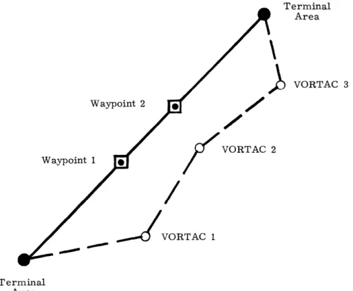
Terminal Area ) VORTAC 3 Waypoint 2 Waypoint 1 VORTAC 2 .... 4VORTAC 1 Terminal Area
Figure 1-1. Improvement to Route Directivity as a Result of Area Navigation Capability
1.2 ' The Benefits of Area Navigation
Operator expense, pilot workload, and traffic congestion are important problems encountered by general aviation. The present navigation techniques which are based on the use of VORTAC ground facilities that require routes directly to and from fixed stations contribute to the problem. Relief lies in the more efficient utilization of airspace, aircraft, and airports. The use of airborne navigation
systems that permit flight over predetermined tracks without the requirement of overflying the ground based facilities would yield a large improvement in airspace utilization. Area navigation (RNAV) offers this capability.
There are three principle applications of the area navigation capability: (1) between any given departure and arrival points along a route structure
so organized as to permit reduction in flight distances or reduction in traffic congestion;
(2) in terminal areas to permit aircraft to be flown on preorganized arrival and departure flight paths to assist in expediting traffic flow and reduce pilot and controller workload; and
(3) to permit instrument approaches within certain limitations to air-ports/runways not equipped with local landing aids. [ 3 ]
The enroute advantages of area navigation capabilities demonstrate them-selves in numerous applications. It provides for improved directivity of routes. Figure 1-1 illustrates the improvement that is possible. The dashed line shows the route that is followed if the ground facilities must be overflown. The solid line
indicates the route that can be flown with area navigation. In the low altitude structure this direct routing can result in significant savings of flight time and, consequently, a savings in operating expense. Area navigation capability also allows for an unlimited number of routes between two terminals. Any course within the coverage area of the reference navigation station can be flown. This permits multiple or parallel route assignment, and traffic can be segregated according to performance level. The result will be less enroute delay and more efficient operation. A third major
advantage afforded by area navigation to enroute operation is the flexibility provided in the selection of weather avoidance routes, restricted area detours, and congested area bypass routes. RNAV allows this operation to be performed in the most efficient manner possible. Using precise course offset and navigation control, the reroute time can be minimized.
Operations with area navigation in the terminal area can result in a reduction of departure and arrival delays by following RNAV standard instrument departures (SID's) and standard terminal arrival routes (STAR's). The adoption of RNAV SID's and STAR's will provide for pilot navigation of commonly flown radar vector paths
and a reduction in communication between the pilots and ground controllers since the pilots can adhere to printed instructions without continuous transmissions from the controllers. This procedure will allow the pilots more time for flight management and
return the navigation function to the cockpit where many people feel that it rightfully belongs.
Area navigation implementation also offers an improvement for airport instru-ment approach operations. RNAV can provide continuous guidance on any track to the end of the runway. This allows straight-in approaches to the uninstrumented runways and can eliminate the requirement for circling approaches under conditions of low ceiling and visibility. It also furnishes continuous measurement of distance along the approach track, and if three-dimensional RNAV is used, the pilot has continuous vertical guidance with selectable glide slope capability and minimum descent altitude (MDA) alarm. Each of these capabilities will result in an increase to instrument approach safety. Furthermore, with this additional approach capability pilots can operate under instrument flight rule (IFR) conditions into airports which might not otherwise be available. This can result in increased operational reliability and makes possible the convenient use of satellite airports so as to avoid the high density traffic areas.
The application of area navigation in general aviation operations can result in higher safety, higher operational reliability, and lower operating cost. The increase in safety results from better weather avoidance routes, better flight management because of the lower communications requirement, and the ability to fly straight-in instrument approaches to uninstrumented runways. The higher operational reliability is a result of the capability to operate under IFR conditions into airports that might not otherwise be available. And finally, the lower operating cost is a direct consequence of the capability to fly more direct routes between origin and destination rather than overflying ground facilities, the provision of less enroute delay due to more efficient traffic management, and the more precise
bypass routes. Each of these improvements reduces the total flight time and, there-fore, the operating cost to the user. Area navigation implementation offers a great deal of promise for general aviation.
1. 3 Specification of Operational Requirements
The present study is a comparative analysis of different area navigation systems applicable to general aviation. In order to properly evaluate the systems, performance specifications must be outlined. The FAA/Industry Task Force on Area Navigation recommended some minimum operational characteristics. One can
sepa-rate the recommendations into two major divisions: those required of the computer/ display functions and those required of the radionavigation system. The computer/ display requirements include provision for display consisting of selected course, distance to waypoint, and cross-track deviation from the selected course; provision
for Waypoint storage and manual insertion of waypoints with a method available for the pilot to check the correctness of his input; parallel offset capability and turn
anticipation; and a failure warning indicator on the total system as well as the sub-systems thereof. These are all very important elements. However, in this analysis it will be assumed that the computer /display capabilities of the different RNAV equip-ment are essentially equal. The system characteristics that are important to this study are those which are factors of the radionavigation system itself. These can be specified in terms of area of coverage, the availability of the signal, and the system accuracy. The area of coverage is the area within which the system
delivers navigation signals that can be received and processed resulting in a naviga-tion accuracy within the specified limits; the signal availability is a measure of the
ability of the system to provide a signal within the coverage area to the accuracy tolerance specified; and the system accuracy is the repeatable accuracy that the system provides with a 95% (20) probability of error less than the stated value.
When planning the implementation of future navigation systems, it is a practical necessity to make modifications consistent and compatible with existing navigation equipment. FAA Advisory Circular AC 90-45, which deals with the subject of area navigation systems for use in the U.S. National Airspace System, states:
"Application of area navigation equipment and procedures in the National Airspace System requires that they be compatible with the VOR/DME
system on which route structure and air traffic control are based. Implementation, therefore, requires that area navigation devices
employed assure proper positioning with respect to the VOR/DME route structure by reference to the geographic locations of VOR/DME
ground facilities. Such systems must further permit navigation along, and within the protected airspace of, conventional VOR routes, air-ways, and terminal procedures. " [4]
A great deal of money has been expended on the VORTAC facilities, and it is expected that "VOR/DME. . .will continue to be the primary reference for short-range navigation for the forseeable future. " [ 5 ] The RNAV system that is used can employ sensor
inputs other than VORTAC if equivalent performance can be demonstrated by means of compliance suitable to such systems. While the author recognizes the inherent limitations of specifying performance requirements in terms of an existing naviga-tion structure, he believes that the practical realities of the naviganaviga-tion and air traffic control situation must be satisfied and that these specifications are sufficient for the initial development.
In order to achieve the maximum utility from RNAV equipment the area of coverage should include the contiguous United States and Alaska. The off-airway operational capability and the potential for approaches to uninstrumented runways
all over the country are major improvements offered by area navigation over the present structure. In this analysis the specification of the coverage area will be that the system must provide service everywhere within the conterminous United States and Alaska from an altitude of 1,500 feet above ground level to 45,000 feet. This service area will encompass that airspace necessary for enroute and terminal area operations.
The ideal signal availability is 100%. A system can approach this ideal value. However, in order to actually achieve it, the reliability of the navigation system components would have to be 100%. This would be prohibitively expensive. Therefore, in this analysis the specification of 100% signal availability will be treated as a goal, and the actual compliance will be dependent on the performance of each system.
The accuracy requirement that has been recommended by the FAA/Industry Task Force for the post- 1982 period is that the enroute tolerance be ± 2. 5 nautical miles and the accuracy in the terminal area be ± 1. 5 nautical miles. These toler-ances are for total system performance. Allowtoler-ances are made for navigation system error, computer error, and flight technical error. This study will require the same performance.
In addition to the requirements relating to performance and safety, economic factors must also be considered. The cost-effectiveness of each system is essential to any comparison among them.
1.4 The Cost-Effectiveness Assessment
Area navigation cost-effectiveness can be evaluated in relation to all classes of airspace users, the government, and the air traffic control system. This study is primarily concerned with a comparative analysis of different area navigation systems for general aviation operations. The cost elements of the cost-effectiveness assessment are:
(1) the facilities and equipment costs for the ground based navigation system installations;
(2) the operations and maintenance costs of the ground based facilities; and
(3) the user cost in terms of the purchase price of the required airborne equipment.
The effectiveness of the different navigation systems will be measured as to how well they can meet the performance requirements as specified earlier in this report.
- VORTAC, Loran-C, and Differential Omega have been selected as the radio-navigation systems of interest. In order to evaluate the systems, one must have an understanding of the individual methods of operation, performance characteristics, and costs. The following three chapters will describe each of the three systems; Chapter Five will furnish the comparative analysis; and finally Chapter Six will display the conclusions.
CHAPTER 2
THE VORTAC SYSTEM OF RADIONAVIGATION
The VORTAC radionavigation system broadcasts the signals which
furnish the present method of short-range air navigation in the United States. This system is actually a combination of two independent navigation systems: the very high frequency omnidirectional range (VOR) and the tactical aerial navigation system
(TACAN). The VOR provides azimuth (theta) information to primarily civil users, and the TACAN provides distance (rho) information to civil aircraft as well as azimuth and distance information to military aircraft. Figure 2-1 illustrates the cooperative arrangement and its service. The azimuth information from VORTAC is supplied as a bearing to or from the reference station, and the distance data is furnished in terms of the slant range in nautical miles from the station. The com-bination of VOR and the distance measuring equipment (DME) portion of TACAN has been adopted by the International Civil Aviation Organization (ICAO) as its standard short-range air navigation system, with the anticipated employment of this arrange-ment now extending through 1985. The short-range air navigation system in the United States consists of approximately 900 VOR facilities, with slightly over 700 of them having collocated TACAN equipment. [6] This large number of VORTAC ground facilities has been acquired and installed at considerable expense to support the air route structure which connects all major sources of traffic flow.
The VORTAC system has been in use for a number of years, and its primary purpose is to provide guidance along designated routes or airways throughout the United States. However, these routes are all aligned radially from the VORTAC stations, and this application ignores the fact that the rho-theta information pro-vided is sufficient to furnish two coordinate position information anywhere within the coverage area of a VORTAC station. When appropriate data processing and displays are available, the VORTAC radionavigation system is capable of pro-viding the information necessary to accomplish area navigation, and, in this light, has been chosen by the author as one of the candidate systems for study in this analysis.
I Distance
ary A c af: Bearing
Mjlitary
AircraftJ ME cDistance Bearing Civil Aircraft TACAN Antenna VOR Antennae VORFigure 2-1. VORTAC Operation
Source: Kayton, M. and Fried, W., Avionics Navigation Systems, John Wiley and Sons, Inc., 1969, p. 193.
2.1 The Very High Frequency Omnidirectional Range
The VORTAC radionavigation system, as stated earlier, is actually the com-bination of two independent navigation systems, i. e., VOR and TACAN. The present analysis will consider each of these systems separately and then combine the capa-bilities of the two in order to examine the area navigation potential of the complete VORTAC system. The very high frequency omnidirectional range was developed by the U. S. Civil Aeronautics Administration (CAA) in the 1940's and gained rapid acceptance as the recognized short-range navigational aid. It was designed to in-corporate several basic considerations founded on CAA experience with earlier navaids. These include:
(1) The indications received by the aircraft are heading insensitive, i. e., they are not affected by the direction of aircraft flight or its flight attitude;
(2) The transmitted signals emanate from one point, originate in one transmitter and are radiated by a closely spaced antenna array;
(3) The azimuth indications are presented to the pilot in such a manner that he may determine his bearing, or fly a course toward or away from the station without resorting to charts or communications with ground stations;
(4) The portion of the frequency spectrum used was chosen to obtain the most consistent reception of signals, day or night, in spite of weather conditions. It also provides for the minimum interference between VOR stations in the system;
(5) Ground station equipment that provides reliability from both an accuracy of signals and a continuity of service basis; and
(6) A provision for simultaneous transmission of voice communications
and identification on the same frequency. [ 7 ]
The VOR provides navigation information on one of eighty frequencies spaced
100 kHz apart in the 108. 0-118.0 MHz segment of the very high frequency (VHF)
band. The portion of the band between 108.0 and 112. 0 MHz is shared with the localizer facilities of the instrument landing system. The VOR operates on the even tenths of megahertz in this segment, and the localizer operates on the odd tenths. For example, 108. 6 MHz could be used for a VOR frequency; however, 108. 7 MHz would be reserved for localizer functions. The VHF band is relatively free of at-mospheric disturbances and precipitation static, and it can, through the use of VOR signals, provide guidance to or from the station on any course the pilot may select.
The quest for a navigation system that provides this omnidirectional infor-mation has been underway for a long time. In fact, in 1916 a simple light system was utilized which introduced the principle of operation to be applied in the much
later developed VOR's. In this early system a rotating light beam and a non-directional signal were combined in such a manner that the rotating beam swung continuously at a predetermined rate, and every time that beam swung past magnet-ic north the nondirectional signal was lighted momentarily. The time interval
be-tween the receptions of the nondirectional signal and the rotating beam could be used to compute the observer's azimuth in relation to magnetic north. As an example,
assume that the rotating beam completes one cycle every 18 seconds. Since this beam would revolve through 3600 every 18 seconds, its angular velocity could be computed to be 200 per second. If the nondirectional signal is sighted exactly 6. 4 seconds before the rotating beacon, the observer would know that he was on the 1280
[6. 4 seconds x 200 per second ] radial from the station.
The VOR system of today provides navigation information using essentially the same principle as the rotating beam of 1916. However, the entire process is accelerated by rotating the beam at an angular velocity of 30 revolutions per second. This high speed makes the measurement of the time interval between the reception of the two signals quite difficult. The problem is resolved by measuring the phase difference between the two signals rather than the time interval. At north azimuth the signals transmitted by these two sources are adjusted to be in phase. As the directional signal rotates it goes out of phase with the signal from the nondirectional source. The airborne receiving equipment measures this phase difference and from it determines the bearing to or from the reference station.
VOR is a phase comparison system. This means simply that the phase of one signal is compared with the phase of another. However, a problem arises in that this type of comparison is possible only between signals whose frequencies are identical, and one also needs to be able to identify the source of each signal. Some-times this identification can be accomplished by time multiplexing the signals and storing the phase information in the receiver circuitry for later comparison. But in the VOR system both signals are transmitted simultaneously, and there needs to be a way to prevent the two from producing a resultant as they pass through space. This is accomplished by transmitting one signal as amplitude modulation and the other as frequency modulation. Detection in the receiver produces two separate audio signals of exactly the same frequency but with measurable phase difference.
The two signals being compared are both 30 Hz signals. One is transmitted in a manner so as to produce a circular radiation pattern. Thus all aircraft at the same instant in time, and at the same distance from the transmitter, receive the same exact phase of this 30 Hz signal. Consequently, this signal is called the
reference signal. The other signal has a radiation pattern shaped like a cardioid, and this pattern is caused to rotate about the station 30 times per second. Figure 2-2 illustrates the cardioid pattern. The airborne equipment which receives this cardioid
signal detects a signal strength which depends on which part of the cardioid it is receiving at any particular instant of time. By the rotation of this pattern amplitude modulation is created, and the received signal strength from the variable signal undergoes a cyclic change which is repeated 30 times per second.
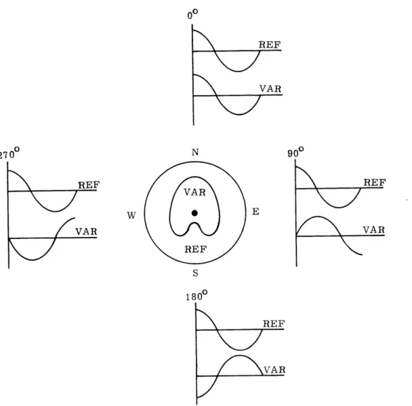
Since both signals occur at the same 30 Hz rate there is a repetitive syn-chronization betweeen the two, and all that is needed is an index point so that they may be compared for phase difference. This index point is established on the ref-erence signal, and the phase of the variable signal is initially adjusted so that the phase difference between the two is 00 at magnetic north. The rotation of the vari-able signal from north azimuth creates a phase difference of one electrical degree for each rotational degree; therefore, an observer can determine his geographical azimuth by simply measuring the phase difference between the phase of the reference signal and the phase of the variable signal. Figure 2-3 illustrates the phase diff-erence that would be measured at the cardinal points of the compass rose. A re-ceiver anywhere within the coverage area of a facility will receive two 30 Hz signals-one from the reference field and signals-one from the variable field cardioid that is passing by. The phase of the signal from the variable field will lag that of the reference field by the exact number of degrees the receiver bears from magnetic north.
The practical application of almost any theoretical concept, including, most certainly, that pertaining to a radionavigation system, introduces errors into the picture. The VOR system is no exception. While its performance is relatively con-sistent it is limited by two major factors:
(1) site errors due to radiowave reflection from objects near the trans-mitting facilities; and
(2) measurement errors which occur while reading the phase difference of the 30 Hz signals in the airborne receivers .
In order to understand the operation of the VOR system one must examine the characteristics of the transmitting and receiving equipment and then look at some of the improvements that have been adopted or suggested for future implementation so as to increase the accuracy and limit the effects of the errors.
2. 1. 1 Conventional VOR Transmitter Operation
During the operation of a conventional VOR transmitter two signals, one omni-directional and one dependent on azimuth, are radiated by an antenna system comprised
Figure 2-2. VOR Variable Signal Cardioid
00 R EF VAR 27 00 N 900 REF REF VA RE VAR R VAR REF S 1800 REF VA R
Figure 2-3. Phase Relationship Between VOR REF and VAR at the Cardinal Compass Points
Source: Federal Aviation Administration, Flight Standards Training Branch, Rho-Theta Navigation Systems, Manual No. FI-202/203B, 1969, p. 2-5.
of four Alford loops. The omnidirectional signal carries three separate elements of intelligence to the receiver:
(1) voice modulation;
(2) a 1020 Hz station identity tone; and
(3) the bearing reference signal.
The voice modulation and the 1020 Hz station identity tones are actually ex-traneous to the navigation function. However, they do provide an important service and will be described briefly. The capability to voice modulate the omnidirectional signal from a VOR transmitter furnishes an additional route of communication to flight service stations or similar air traffic control functions. This is a simplex type of communication where the ground facility can only transmit and the airborne equipment can only receive, but it does provide a useful emergency outlet. In addi-tion, some VOR stations use the voice modulation to identify the facility, e. g., every
15 seconds the voice transmission "This is Lake Henry VOR" may be carried by the
omnidirectional signal. Identification of all stations is made by using the 1020 Hz station identity tones. The VOR station identification code consists of a three letter characteristic formed by dots and dashes in accordance with the Morse Code, e. g.,
the Anchorage (ANC) VOR would be coded as *- /- -/ -'* --. This signal is
trans-mitted by the station every 6 seconds, and the lack of the identity tone is used to indicate that a station is out of tolerance or off the air.
The third element of intelligence in the omnidirectional transmission is the bearing reference signal. Its presence is, obviously, crucial to the navigation function. The reference field is generated when an audio signal, whose frequency is constantly being changed, is used to amplitude modulate the VOR carrier trans-mission. This audio signal is a 9960 Hz transmission which is frequency modulated
± 480 Hz sinusoidally at the rate of 30 Hz. If this signal were received on a con-ventional receiver it would sound like a high pitched tone with a 30 Hz wobble. This wobble is a means of carrying 30 Hz intelligence through space.
The mechanical process which initiates this transmission is quite simple.
A tone wheel is driven by an 1800 rpm (30 rps) motor; and on this wheel are 332
teeth which are arranged in a slightly staggered manner so as to impart a cyclical variation between 9480 Hz and 10, 440 Hz with the rotation of the motor. The fre-quency modulated signal from this tone wheel is then used to amplitude modulate the VOR carrier signal. The airborne receiver uses numerous filters, limiters, and discriminators to reproduce the 30 Hz intelligence which will provide the reference for the bearing phase comparison.
The azimuth related signal is generated coincidentally with the reference transmission. The same shaft that drives the aforementioned tone wheel also drives a capacitative goniometer which is being fed by the station transmitter. This goniom-eter is responsible for furnishing the cardioid shaped pattern that creates the
azimuth related signal.
The creation of this azimuth related signal occurs through the use of a clever radio frequency (RF) feed arrangement. A portion of the energy that was generated by the transmitter and modulated at the 9960 Hz rate is removed and fed, after
de-modulation, to a goniometer. This goniometer has two functions:
(1) it converts the carrier frequency into upper and lower 30 Hz sideband frequencies; and
(2) it provides two outputs, separated 900 in phase, each feeding an Al-ford loop antenna pair.
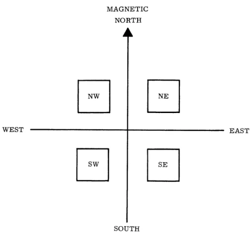
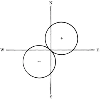
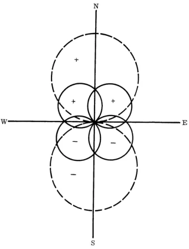
The four Alford loops that comprise the VOR antenna system are mounted on the corners of a square. They are combined in such a manner that the northwest and southeast loops are designated as pair No. 1. and the northeast and southwest loops as pair No. 2. Figure 2-4 illustrates this arrangement. The RF feed to the loops of a pair is from a common feed line but connected so as to make the radiation of one loop 1800 out of phase with the radiation from its companion loop. Therefore, the radiation from a pair produces a figure eight pattern with one lobe having energy phased directly opposite to that of the other lobe. Figure 2-5 illustrates this prin-ciple. If one considers a moment of time when the power fed to both pairs of loops is equal, the radiation pattern is four lobes of equal intensity - one figure eight from pair No. 1 and one figure eight from pair No. 2. Since pair No. 2 is configured 900 from pair No. 1, its radiation pattern is adjacent. The phasing between the pairs is such that the two lobes pointing north have the same phase, and this arrangement produces one resultant lobe of that phase. See Figure 2-6. The same thing happens to the two lobes directed south. Consequently, when equal power is furnished to all loops, the resultant radiation pattern is one large figure eight with lobes having opposite phase. As previously mentioned, the goniometer provides two outputs, sep-arated 900 in phase, to the Alford loop antenna pairs. One output has an amplitude proportional to the sine, and the other an amplitude proportional to the cosine, of the rotational angle of the goniometer rotor. Hence, as the RF energy from the No. 2 antenna system is building to a maximum, the energy from the No. 1 system will be collapsing to 0. For example, at 300 azimuth the goniometer plates are in a position
where antenna pair No. 1 would be producing -, i. e., sin 300, of its total available
power, while pair No. 2 is generating 0. 866, i. e., cos 300, of its total available power. The addition of the two would produce a resultant figure eight pattern with its maximum positive lobe directed toward 300 of azimuth. The collapsing and building of the two patterns is a continuous process that produces a smoothly ro-tating figure eight resultant.
MAGNETIC NORTH NW WEST
SW
NE EAST SE SOUTHNORTHWEST-SOUTHEAST LOOPS: PAIR NO. NORTHEAST-SOUTHWEST LOOPS: PAIR NO.
Figure 2-4. Orientation of the Four Alford Loops in the VOR Antenna System
S
FIGURE 8 from PAIR NO. 1
FIGURE 8 from PAIR NO. 2
Figure 2-5. Radiation Patterns from Alford Loop Pairs in the VOR Antenna System
A
w IE
/
c
I'
I
S
Figure 2-6. Resultant Figure 8 Radiation Pattern for All Alford Loops Having Equal Power Input
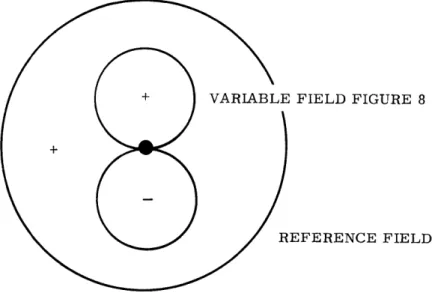
When the figure eight pattern from the sideband antenna pairs is combined in space with the uniform phase field of the carrier, there is a reinforcement between the positive phase of the figure eight pattern and the positive phase of the uniform phase field; vice versa for the negative phase of the figure eight. This, in effect, creates a rotating cardioid shaped pattern for the variable field. Figure 2-7 por-trays this phenomenon. This cardioid shaped pattern amplitude modulates the VOR carrier signal and, once detected in the airborne equipment, provides the azimuth related signal used for phase comparison purposes.
In summary, the two navigation intelligence bearing signals of the VOR sys-tem are transmitted simultaneously. One, the azimuth dependent signal, is radiated
as simple 30 Hz amplitude modulation of the VHF carrier. The other, the omni-directional signal, is transmitted as frequency modulation of a 9960 Hz subcarrier which in turn amplitude modulates the VHF carrier. Figure 2-8 illustrates
schemat-ically the design of a conventional VOR transmitter. 2. 1. 2 VOR Receiver Operation
The primary purpose of the airborne equipment associated with the VOR sys-tem is to detect the 30 Hz amplitude modulated signal produced by the rotating car-dioid pattern and compare it with the 30 Hz frequency modulated reference. Figure 2-9 depicts the basic receiver functions. At the output of the 108.0-118.0 MHz receiver is an AM detector. The purpose of this detector is to pick off the various amplitude modulating signals from the VHF carrier. The detector output is com-prised of four elements:
(1) voice modulation, if it has been used at the transmitter; (2) coded 1020 Hz identification tones;
(3) a 300 Hz signal produced by the rotating cardioid; and
(4) a 9960 Hz tone which has been frequency modulated * 480 Hz by the 30 Hz reference signal.
The voice frequencies and the identification tone are relayed to the audio distribution system of the aircraft. The 30 Hz information which was amplitude modulating the carrier, i. e., the azimuth dependent signal, is filtered to remove other components and fed to the phase comparison circuitry. The 9960 Hz subcarrier information is removed by the 10kHz filter and then limited and applied to an FM detector whose output is the 30 Hz reference signal. After appropriate filtering this is compared with the azimuth dependent signal, and bearing information is the result.
There is a good deal of experimental evidence that indicates that a major portion of the ills of the VOR system can be attributed to the airborne equipment and the airborne environment. Professor McFarland of Ohio University has stated that all evidence collected during the experimental portion of a fairly extensive investi-gation definitely indicates that the receiver is the major contributor to the course error in the information presented to the pilot. [8] It has been established that, in
VARIABLE FIELD FIGURE 8
REFERENCE FIELD
INDIVIDUAL RADIATION PATTERN
COMPOSITE RADIATION PATTERN OF CARDIOID SHAPE
Figure 2-7. Formation of Cardioid Shaped Composite Pattern in the VOR System
Four Alford Loops
Bridge L/t Bridge
Continuous wave modulated by tone wheel, voice, 1020 Hz
identity tone Trans-mitter 9960 Hz FM Modulation Eliminator + 480 Hz at Tone Wheel 30 Hz 1800 rpm Continuous Wave motor Goniometer
Continuous wave, modulated 30 Hz by goniometer, 900 apart
Figure 2-8. Schematic Drawing of Conventional VOR Transmitter
Source: Kayton, M. and Fried, W., Avionics Navigation Systems, John Wiley and Sons, Inc., 1969, p. 165.
VOR Antenna
Bearing Information
Figure 2-9. Schematic Drawing of Conventional VOR Receiver
Source: Kayton, M. and Fried, W., Avionics Navigation Systems, John Wiley and Sons, Inc., 1969, p. 167.
order to make theoretical calculations match observed facts with respect to VOR scallops and bends, reflection coefficients of from 100 to 1000 times predicted values would have to be assumed. [9] On the other hand, there is good agreement between
theory and observed facts with respect to low frequency modulation of the VOR space field as a result of aircraft motion in the multipath space field. It appears that the receiver processing of the low percentage low frequency modulation is introducing large errors. McFarland's most distressing discovery was that new receivers do not necessarily provide improved performance in the rejection of signals which produce the course errors. Demonstrations, both in the air and on the test bench, showed that old and new receivers alike were, in themselves, producing excessive scallops and bearing errors when operated in the real-life VOR environment. Because different receivers were used in parallel, and different reactions were obtained, the receiver design is believed to be the most critical in determining the extent to which multipath will af-fect indicated course position. [10] The errors that result do not reflect the effects of receiver calibration, but rather the receiver design itself which inherently
pro-vides characteristics that either favor or reject the effects of the multipath signals. The receivers need the capability to be calibrated accurately and reject the low
per-centage low frequency amplitude modulation. Along with the normal improvements intended to capitalize on the various advantages of solid state devices, such as
in-creased reliability and performance with reduced size, weight, and cost, there is a trend toward designing receivers with the above capability in mind. The resultant
receiver accuracy in such cases can be assumed to be on the order of 10. Table 2-1 enumerates the characteristics of several representative VOR receivers presently available on the market. The cost of the VOR receivers for general aviation opera-tions can vary anywhere from $800 up to $7000, but, for the purposes of the present analysis, it is assumed that a highly accurate VOR receiver can be obtained for about $1500-2000.
2.1. 3 VOR Accuracy Capability
The performance, with respect to accuracy, of any radionavigation system is dependent upon essentially three elements:
(1) calibration and control of the transmitter operation; (2) propagation of the signal through space; and
(3) receiver processing and display.
The FAA employs extensive monitoring and flight check programs to ensure that the VOR system provides signals within specified accuracy tolerances.
Table 2-1
REPRESENTATIVE VOR RECEIVERS
Characteristics
Aircraft Radio Corp. 841 Nav System (Cessna nav 800)
R-442A Nav System (Cessna nav 400)
200 channels; panel mtd. cntrl. & ind.; remote rcvr. & cnvrtr.; solid state; RMI 200 channels; panel mtd.; solid state $3, 495 $1, 600 Collins Radio 51R-7A 51RV-1
380 channel; covers VHF comm.; remote mtd.; solid state; RMI; RNAV
200 channel; remote mtd.; solid state; RMI; RNAV
$2, 640
$6, 468
King Radio KNR 600A
KNR 660A
200 channel; panel mtd. sel.; remote mtd. rcvr.; solid state 200 channel; panel mtd. sel. ; remote mtd. rcvr.; solid state; RMI $2, 550 $3, 475 Narco Avionics NAV-11 NAV-111
200 channel; panel mtd. self-contained; solid state
200 channel; panel mtd. rcvr.; solid state; HSI or RMI
$ 925
$1, 170
RCA Avaition Equip.
AVN-210A 200 channel; 40 GS; MB; panel $4, 140
mtd.; solid state
The basic control of the transmitter operation is related to the antenna sys-tem and its adjustments. Modifications to the current amplitudes and phase re-lationships in the system are accomplished by mechanical adjustments to the current dividing and phasing networks; and once adjusted they remain constant over a long period of time. The system must be adjusted so that the phase difference between the omnidirectional signal and the azimuth related one is as close as possible to 00 at magnetic north and then varies accordingly around the compass rose. The ground station accuracy is determined from measurements made at the edge of the station counterpoise, and in order to commission the facility, the maximum spread of the error must not exceed 1. 50. Most of the errors are cyclic in nature, and an analy-sis of the error curves can be made to determine which of the current amplitude or phase relationships needs correction. Once this is accomplished, a VOR monitor is used to keep a constant check on the signals and determine that their level and phase are maintained within prescribed tolerances. The monitor performs the following functions:
(1) it keeps a continuous check on the amplitude of the transmitted ref-erence signal and will cause an alarm if this signal decreases by 13% or more;
(2) it keeps a continuous check on the variable signal amplitude and will cause an alarm if this signal decreases by 13% or more;
(3) it keeps a continuous check on the omnicourse at a selected azimuth about the station and will cause an alarm if the input phasing changes
more than 10;
(4) it isolates the 1020 Hz identification signal and routes this audio fre-quency to a monitor amplifier either at the VOR or at the station con-trolling the VOR facility. Loss of this 1020 Hz identification, as seen
at the monitor amplifier, will cause the monitor to indicate an alarm; (5) it incorporates a means of self test through the use of the tone wheel
output so as to check for phase shifts or faulty stages within the mon-itor itself; and
(6) it incorporates circuits that allow the monitor to be used for ground checking of the VOR. [11]
By employing this monitor system the FAA can be confident that the phase and strength of the signals from the transmitter facility are maintained at the desired level.
Errors due to the propagation of the signal through space occur primarily as a result of the multipath effect. This phenomenon is present when signals from the transmitter are reflected by objects and then relayed to the airborne receiving
and can cause significant bearing errors. The source of reflection can be any num-ber of things, ranging from raindrops and snowflakes to building and trees. In prac-tice, the errors that result from the reflections are divided into two categories:
(1) atmospheric propagation errors; and (2) siting errors.
The atmospheric propagation errors yield very small excursions from the norm. Experimental work performed by Professor McFarland and his cohorts at Ohio University has demonstrated that the atmospheric propagation effects produce only about 0. 20 course error with a 3 a- probability. [12] In that we cannot hope to control, improve, or change the medium in which the VOR signal is propagating, this is felt to be the ultimate limit to VOR system accuracy.
The siting errors are another matter. The bearing discrepancies that appear as a result of siting errors can be very large. Locating suitable VOR sites is a difficult problem because buildings, wires, fences, and trees reflect the electromag-netic radiation from the transmitter and cause numerous bearing errors. These errors appear as course scalloping, course roughness, course bends, and, in special
cases, fixed errors. The reader is referred to reference 13 for a good description of the siting problem and summary of experimental results. In an effort to minimize
these errors siting criteria have been established. The transmitter must be located on relatively flat terrain or on top of a knoll which has reasonably uniform contours over a radial distance of 1500 feet from the station. The area should be cleared of all obstacles capable of providing serious reradiation, and the line of sight to clear all obstacles within a radius of 2000 feet should subtend a vertical angle of less than
0
2 . In addition, the power and telephone lines to the station should be installed un-derground up to a distance of 750 feet from the transmitter. However, some sites are not capable of meeting these standards, and compromises must be accepted. In fact, it is estimated that a significant percentage of present VOR's (25%) are currently restricted due to poor signal quality, and a large percentage are impaired to a lesser extent. [14]
Because actual station performance may be degraded to an unacceptable level by things far removed from the station, e. g., terrain reflections causing scalloping, roughness, and bends, the ground monitor system, as described above, is incapable of guaranteeing acceptable performance by the VOR station. Specially equipped flight inspection aircraft are used to remove this limitation. They check all facilities be-fore commissioning and accomplish periodic performance checks to ensure that the signal made available to the user is within tolerance. The standards established are such that the alignment of all electronic radials will be within 2. 50 of the correct magnetic azimuth; momentary deviations of the course due to roughness, scalloping,