Publisher’s version / Version de l'éditeur:
Vous avez des questions? Nous pouvons vous aider. Pour communiquer directement avec un auteur, consultez la première page de la revue dans laquelle son article a été publié afin de trouver ses coordonnées. Si vous n’arrivez pas à les repérer, communiquez avec nous à PublicationsArchive-ArchivesPublications@nrc-cnrc.gc.ca.
Questions? Contact the NRC Publications Archive team at
PublicationsArchive-ArchivesPublications@nrc-cnrc.gc.ca. If you wish to email the authors directly, please see the first page of the publication for their contact information.
https://publications-cnrc.canada.ca/fra/droits
L’accès à ce site Web et l’utilisation de son contenu sont assujettis aux conditions présentées dans le site LISEZ CES CONDITIONS ATTENTIVEMENT AVANT D’UTILISER CE SITE WEB.
Fire Study (National Research Council of Canada. Division of Building Research), 1970-03-01
READ THESE TERMS AND CONDITIONS CAREFULLY BEFORE USING THIS WEBSITE. https://nrc-publications.canada.ca/eng/copyright
NRC Publications Archive Record / Notice des Archives des publications du CNRC :
https://nrc-publications.canada.ca/eng/view/object/?id=3aea452a-388a-4c85-ab8b-c22ea3924ceb https://publications-cnrc.canada.ca/fra/voir/objet/?id=3aea452a-388a-4c85-ab8b-c22ea3924ceb
NRC Publications Archive
Archives des publications du CNRC
For the publisher’s version, please access the DOI link below./ Pour consulter la version de l’éditeur, utilisez le lien DOI ci-dessous.
https://doi.org/10.4224/40001363
Access and use of this website and the material on it are subject to the Terms and Conditions set forth at
Fire endurance of selected non-loadbearing concrete masonry walls
Allen, L. W.
NATIONAL RESEARCH COUNCIL OF CANADA <- 5
9
., -*' -, . * .<? :. :, > -. DIVISION O F BUILDING RESEARCH 1,: . - 'FLRE ENDURANCE O F SELECTED NON-LOADBEARING CONCRETE MASONRY WALLS
L. W. A l l e n F i r e Study No. 25 of the Division of Building R e s e a r c h Ottawa M a r c h 1970
PREFACE
A planned s e r i e s of t e s t s has been c a r r i e d out a s the major p a r t of a p r o g r a m of r e s e a r c h under the cooperative r e s e a r c h fellowship arrangement between the National Concrete P r o d u c e r s Association and the National R e s e a r c h Council of Canada. It was decided that the program should be on the f i r e endurance of concrete masonry walls and that, for various reasons, extensive testing over a range of r e p r e - sentative concrete products should be c a r r i e d out. A compromise had t o be made between the requirements for r e s e a r c h purposes involving the testing of adequate numbers of specimens in properly designed s e r i e s and, on the other hand, t o obtain some information on a s wide a range of factors and of Canadian products a s could be achieved within the limits of the program. All of t h e concrete products involved have been made in the plants of Canadian manufacturers and a r e believed t o be r e p r e s e n t a - tive of good Canadian production. Because of the restrictions on the
number of t e s t s that could be c a r r i e d out within the two-year period, it was decided t o deal only with 4- and 6-in. masonry units such a s
a r e used in interior partitions. This decision resulted in the elimination of loadbearing t e s t s since interior partitions a r e commonly non-loadbearing.
The work now reported covers principally the t e s t r e s u l t s a s determ.ined from f i r e t e s t s on full s c a l e (10 ft by 12 ft) and s m a l l panel ( 2 4 f t by 2 i ft) specim.ens. These t e s t s wer e'conducted during the two-
year period from October 1967 t o 1969 at the NRC F i r e R e s e a r c h Laboratory. Some evaluation of the r e s u l t s and s o m e conclusions have been drawn and a r e presented in this report. A substantial amount of additional inform- ation covering the physical properties of the m a t e r i a l s tested has been obtained through special laboratory t e s t s c a r r i e d out concurrently with the testing program. This information goes beyond that normally consid- e r e d in the routine evaluation of quality of concrete masonry units and includes such t e s t s a s t h e r m a l conductivity c a r r i e d out over the range of t e m p e r a t u r e s encountered in the f i r e t e s t s a s well a s dilation and t h e r m a l analysis. This additional information should permit much
f u r t h e r study of the possibilities of predicting f i r e endurance by calcula- tion, and this will be taken up in the second t e r m of the fellowship. The r e s u l t s of this further work and the additional special physical t e s t
information will be reported at a l a t e r date.
Ottawa March 1970
N. B. Hutcheon
TABLE O F CONTENTS
Page
SPECIMENS AND TESTS F i r e T e s t Specimens Description of T e s t Units Materials Conditioning of Specimens Testing P r o c e d u r e DISCUSSION O F RESULTS F i r e T e s t S e r i e s
F i r e Endurance of Masonry a s Affected by Aggregate Type, Thickness and Moisture
Increase in F i r e Endurance of Concrete Masonry due to P l a s t e r
Effect of Sand Replacement on the F i r e Endurance of Lightweight Concrete Masonry Units
Compar ison of Fir e Endurances f r o m T e s t s on *Small
Panels' with those obtained f r o m 'Standard' F i r e T e s t Specimens
F i r e Endurance of Autoclaved vs Low P r e s s u r e Cured Masonry Units
F i r e Endurance of Walls built with 2
-
and 3 -Core Concrete Masonry UnitsSUMMARY
ACKNOWLEDGEMENTS
REFERENCES TABLES 1 TO 21
FIGURES 1 T O 60
FIRE ENDURANCE OF SELECTED NON- LOADBEARING CONCRETE MASONRY WALLS
L. W. Allen
*
This i s the f i r s t of a s e r i e s of reports on the f i r e endurance of concrete masonry units a s determined from f i r e t e s t s of full scale
specimens (10 ft by 12 ft) and small panel specimens ( 2 t ft by 2f ft).
The t e s t program was designed to develop information on the f i r e performance of various units supposedly representative of those which a r e currently being produced by some Canadian manufacturers. Tests were conducted during a 2-year period at the N. R. C. F i r e Research Laboratory.
Thirty-seven different types of units were included in the program from which a total of 60 test specimens were built and subjected to f i r e exposure. Sixteen of the tests were c a r r i e d out on 'standard' t e s t specimens in accordance with the requirements of ASTM E l 19 -67,
.
Failure c r i t e r i ain these was based on both heat transmission and structural integrity. In
the remainder of the t e s t s the procedures of ASTM E l 19-67 were followed, generally, except that t e s t s were conducted on non-standard 'small panel' specimens (wallettes). For these t e s t s , f i r e endurance periods were determined solely by the ASTM c r i t e r i a for temperature r i s e on the unexposed surface.
Variables investigated in the t e s t s e r i e s included thickness of masonry, type of aggregate, method of curing, geometry of units, size of f i r e t e s t specimen, influence of plaster protection, and effect of sand replacement for lightweight aggregate units.
SPECIMENS AND TESTS F i r e Test S ~ e c i m . e n s
Tables 1 through 6 describe the various f i r e t e s t s c a r r i e d out
f o r units made with the following concrete aggregates : siliceous gravel,
calcareous gravel, expanded slag, expanded shale, expanded clay and
*
Concrete Producers Research Fellow, National Research Council ofCanada. (Mr. Allen is the holder of the f i r s t Fellowship, 1967-1969,
and is now engaged on a second two-year t e r m for work on a co-operative
r e s e a r c h program of the National Concrete Producers Association jointly with the National Research Council of Canada being c a r r i e d out in the
pumice. T e s t specimens w e r e either 4 o r 6 in. thick and both hollow and solid m.asonry units w e r e included. Hollow m a s o n r y was predominantly 2 c o r e and the m a j o r i t y of units w e r e low p r e s s u r e cured. F o r each of the 4 types of lightweight aggregate units, t e s t specimens consisted of units of ( a ) 100 p e r cent lightweight aggregate; (b) 90 p e r cent lightweight aggregate t 10 p e r cent n a t u r a l sand; and ( c ) 80 p e r cent lightweight aggregate t 20 p e r cent n a t u r a l sand, respectively.
During f i r e exposure, standard t e s t specimens w e r e r e s t r a i n e d on four s i d e s by m e a n s of a reinforced p r e c a s t concrete r e s t r a i n i n g f r a m e . No r e s t r a i n t was afforded s m a l l panel wallettes during t e s t s . None of t h e specimens was loaded during f i r e exposure.
Masonry walls and wallettes w e r e laid up by a recognized m a s o n r y contractor and generally w e r e of good commercia.1 grade workmanship. P l a s t e r i n g of selected t e s t specimens was c a r r i e d out by a local contractor and workmanship was average. Variations in thickness of p l a s t e r w e r e detected on s u r f a c e s of s o m e walls but w e r e generally slight.
Description of T e s t Units
Concrete m a s o n r y units for t e s t specimens w e r e provided f r o m r e g u l a r production r u n s of five major Canadian producers. Nearly 3300 units w e r e produced and after curing for 28 days they w e r e shipped t o N. R. C. 'S
F i r e R e s e a r c h Laboratory. Units w e r e considered t o be r e p r e s e n t a t i v e of c u r r e n t Canadian production.
An independent testing l a b o r a t o r y c a r r i e d out physical p r o p e r t y measurem.ents i n accordance with ASTM Designations C20, C135 and (3140 on five s a m p l e s of each of the 37 types of units. Tables 7 through 12 show physical p r o p e r t y data for units of each aggregate type. Information on concrete m i x design, supplied by the r e s p e c t i v e block m a n u f a c t u r e r s i s given in Table 13.
Manufacturing procedure.
-
Siliceous gravel units, f r o m Hull, Quebec,w e r e allowed t o p r e s e t a t atm.ospheric t e m p e r a t u r e for 4 h r . At the end of the p r e s e t period s t e a m was introduced and the t e m p e r a t u r e of the kiln r a i s e d t o 170°F. The blocks w e r e c u r e d at this t e m p e r a t u r e f o r about 12 h r . Autoclaved units w e r e allowed to p r e s e t f o r 3 h r . P r e s s u r e i n the kiln reached 140 p s i in 2$ h r and was held for an additional 5 h r . The blowdown t i m e r e q u i r e d was approximately 1 5 minutes.
Calcareous gravel units were manufactured in Thorold, Ontario. Following a preset period of 3 h r , steam was introduced into the kiln and after 2 h r reached a maximum temperature of 165" F. Soak period was 19 h r completing a total c u r e cycle of 24 h r .
Pumice aggregate units, from Montreal, Quebec, were allowed a preset time of 4 h r . Maximum kiln temperature was 180" F. Hold period was 5 h r and soak period was 15 h r providing a 24-hr cure cycle.
For expanded clay units, a preset period of 2 h r was allowed. The maximum kiln temperature after 1 h r was 135" F and 180" F at the end of 3 h r . Maximum temperature was held for 1 h r followed by a 10 -hr soak period. Expanded clay units were produced in Winnipeg, Manitoba.
Expanded shale units, from Scarborough, Ontario, received a preset period of 2 h r . Maximum kiln tem.perature reached in 4 h r was
160" F with a 2-hr hold period. Soak period was 16 h r giving a total c u r e cycle of 24 h r .
Expanded slag units, except types C, CX, CY and AZ (Table 9),
were from Pickering, Ontario. P r e s e t time varied from 1 to 3 h r
followed by an 8 -hr steam cure. Maximum kiln temperature was 170" F
and units were allowed to soak for 6$ hr. Expanded slag units types C, CX and CY were made in Toronto, Ontario. P r e s e t time was 1 h r and a maximum kiln temperature of 180" F was reached in 3 hr. Hold and soak periods were 2 and 12 h r respectively completing a 18 -hr total cure cycle. Autoclaved expanded slag units (type AZ) produced in Hamilton, Ontario, were allowed a preset period of 4 hr. Maximum kiln temperature of 350°F at a p r e s s u r e of 150 psi was reached in 3 h r . Hold period was 5 h r followed by a 15-minute blowdown period.
Materials
Cement. -Type I (Normal) Portland Cement was used throughout. Aggregates.
-
Petrographic information for aggregates of siliceousand calcareous gravel units, obtained by generally following the procedures of ASTM Method C295-65 is given in Appendix A. Aggregates in the
fine and c o a r s e size fractions for siliceous gravel units were from Hull, Quebec. Calcareous gravel units were produced with fine aggregate f r o m P a r i s , Ontario, and c o a r s e size fractions from Thorold, Ontario.
Information on aggregate gradation and unit weight for n o r m a l weight units is given in Appendix A. Maximum aggregate s i z e was 3/8 in.
Of the four types of lightweight units, expanded shale and expanded slag aggregate w e r e used in both the fine and c o a r s e s i z e fractions. Maximum s i z e of expanded slag aggregate from Hamilton, Ontario, and expanded shale aggregate from Toronto, Ontario was 3/8 in. Pumice aggregate units w e r e produced with m a t e r i a l in the fine s i z e fractions only, brought in from. Yali, an island in the Mediterranean Sea near Greece. Aggregates in the fine and medium s i z e fractions f r o m n e a r Winnipeg, Manitoba, w e r e used in the production of expanded clay units. Data on aggregate gradation and unit weight for lightweight units a r e a l s o given in Appendix A.
Replacem.ent Sands.
-
T h r e e different types of natural sands w e r e usedto manufacture partially sanded lightweight units. Material for sanded expanded slag and expanded shale units was a natural m o r t a r sand, 86. 5 siliceous by weight from Toronto, Ontario. Sanded pumice aggregate units w e r e produced using a 90 per cent siliceous natural m o r t a r sand from n e a r Montreal, Quebec. Replacement m a t e r i a l for sanded expanded clay units was a 78 p e r cent calcareous concrete sand f r o m Winnipeg, Manitoba. Information on the gradation and petrography of replacement sands m a y be found in the Appendix.
M o r t a r .
-
M o r t a r used t o construct t e s t walls and panels conformed tothe requirements of ASTM Designation C270-64T. Type N m a s o n r y
m o r t a r approximately 3/8 in. thick mixed from recommended proportions of Type H m a s o n r y cement and damp loose aggregate was used throughout. Compressive strength of m o r t a r was determined from t e s t s on 2-in.
m o r t a r cubes. S e v e r a l samples w e r e prepared from each batch of m o r t a r and allowed to s e t 24 h r before moulds w e r e removed. M o r t a r cubes w e r e then placed in a curing chamber maintained at 95 t o 100 p e r cent
relative humidity at a t e m p e r a t u r e of 72.8 t o 73. 8" F. After 28 days
samples w e r e removed from the curing chamber and tested in compression. Strength levels, generally, w e r e found t o be well above the minimum
p e r m i s s i b l e value of 750 p s i at 28 days.
P l a s t e r .
-
P l a s t e r i n g of selected walls and panels was c a r r i e d out in accordance with applicable r e q u i r e m e n t s of CSA Standard A82. 30 -1 965. T h r e e coats, including a finish coat, w e r e applied directly t o both sidesof specimens a s specified below:
1/4 in. s c r a t c h coat, 1 p a r t gypsum: 2 p a r t s sand (by weight).
Average density: 105 lb/ft
.
Average c o m p r e s s i v e strength of four c y l i n d e r s : 419 psi.1/4 in. brown coat, 1 p a r t gypsum: 3 p a r t s sand (by weight).
Average density: 105 lb/ft
"
.
Average c o m p r e s s i v e strength of four cylinders : 473 psi.1/8 in. finish coat, in accordance with good p r a c t i c e . Conditioning of S p e c h e n s
ASTM E l 1 9 s t a t e s , " P r i o r to f i r e t e s t , constructions shall be conditioned with the objective of providing, within a reasonable t i m e , a m o i s t u r e condition within the specimen approximately r epr e
-
sentative of that likely to exist in s i m i l a r construction in buildings. F o r purposes of standardization, this condition i s to be considered a s that which would be established at equilibrium resulting from drying in an ambient atmosphere of 50 per cent relative humidity at 7 3I?.
However, with s o m e constructions, it m a y be difficult o r impossible to achieve such uniformity within a reasonable period of time.
Accordingly, where t h i s i s the c a s e , specimens m a y be t e s t e d when t h e dampest portion of the s t r u c t u r e .
.
. . .
h a s achieved a m o i s t u r econtent corresponding to drying t o equilibrium with a i r in the range of 50 t o 75 per cent r e l a t i v e humidity at 73 f 5 F. If, during the conditioning of the specimen it a p p e a r s desirable or i s n e c e s s a r y to u s e a c c e l e r a t e d drying techniques, it i s the responsibility of the labo- r a t o r y conducting t h e t e s t to avoid p r o c e d u r e s which will significantly a l t e r the s t r u c t u r a l or f i r e endurance c h a r a c t e r i s t i c s of the specimen or both. . .
.
I IDuring the conditioning period the r e l a t i v e humidity (in the p o r e s ) of the m a s o n r y units was m e a s u r e d at m o r e or l e s s r e g u l a r
intervals. By m e a n s of a laboratory c o r e drill, cylindrical s a m p l e s of about 7/8 in. diameter and 2.82 in. length w e r e taken from the wall through the web sections of the units. Each sample was divided into t h r e e s m a l l e r cylinders about 0. 94 in. long which w e r e subsequently c r u s h e d into pieces not l a r g e r than 1/4 in. and analyzed s e p a r a t e l y f o r relative humidity. The r e l a t i v e humidity was m e a s u r e d by m e a n s of an "El-Tronics" portable hygrometer. The holes left in the m a s o n r y work after r e m o v a l of the cylindrical s a m p l e s w e r e filled with f a s t - setting high - t e m p e r a t u r e m.ortar
.
When the relative humidity near mid-depth of units was found t o be between 50 and 75 per cent, specimens w e r e subjected t o standard f i r e exposure.
In some c a s e s , initial RH measurements indicated interior humidity levels of units w e r e below the 50 per cent minimum s e t out by E119. These specimens w e r e moved into a conditioning chamber where the t e m p e r a t u r e was maintained between 80 and 9 0 ° F and the relative humidity between 90 and 100 per cent. They w e r e subjected t o the f i r e t e s t when subsequent measurements indicated humidity levels at mid-depth had reached or exceeded 50 per cent.
Certain of the t e s t specimens w e r e also found to contain
excessive moisture. Relative humidity measurements indicated levels of a s much a s 85 t o 90 per cent at mid-depth of some units. AS ASTM E l 19 p e r m i t s artificial drying, provided no abnormal changes a r e brought about in s t r u c t u r a l properties, these specimens w e r e subjected t o uniform accelerated drying at a t e m p e r a t u r e of 100°F. This t e m p e r - a t u r e was considered sufficiently low s o a s not t o induce any physico- chemical changes in the s t r u c t u r e of the concrete and permitted the development of acceptable m o i s t u r e levels.
Age of walls and panels at time of test ranged, generally, f r o m one t o four months.
Testing P r o c e d u r e
Conduct of f i r e t e s t s .
-
F i r e endurance t e s t s on masonry walls w e r e c a r r i e d out at the NRC/DBR a in accordance with ASTM DesignationE119-67. The furnace t e m p e r a t u r e was m e a s u r e d by nine symmetrically distributed thermocouples enclosed in 13/16 -in. o. d. Inconel tubes of 0. 035-in. wall thickness, the tubes equipped with carbon s t e e l cap at the tip. The hot junction of the thermocouples was placed 6 in. away from the exposed surface of the specimen. Both the individual temper
-
a t u r e s at nine points of the furnace and the average of the nine temper-
a t u r e s w e r e recorded. The fuel input into the furnace was controlled in such a way a s t o make the average t e m p e r a t u r e follow the p r e s c r i b e d t e m p e r a t u r e v e r s u s t i m e curve ( F i g u r e 1).Unexposed surface t e m p e r a t u r e s of standard specimens w e r e m e a s u r e d by nine thermocouples covered with asbestos pads, 6 in. s q u a r e and 0. 4 in. in thickness, distributed a s shown in Figure 2. F o r walls of hollow concrete m a s o n r y t h r e e thermocouples ( NOS. 1, 2, and 4) w e r e located adjacent t o web portions of blocks and s i x thermocouples (Nos. 3, 5, 6, 7 , 8 and 9) w e r e positioned over cavity a r e a s of units. Both individual t e m p e r a t u r e s at nine points of the unexposed s u r f a c e and the average of the nine t e m p e r a t u r e s w e r e recorded.
During the t e s t standard specimens w e r e r e s t r a i n e d on all four edges by a p r e c a s t reinforced concrete f r a m e a s detailed in F i g u r e s
3A, 3B, and 3C*.
Deflections a t c e n t r e s of walls during heating w e r e observed
and r ecor ded. Measurements of residual deflections w e r e taken
24 h r after completion of the f i r e t e s t .
F i r e endurance t e s t s on wallettes w e r e c a r r i e d out using one of two s m a l l scale f i r e t e s t units maintained by N. R. C. 's F i r e R e s e a r c h
~ a b o r a t o r ~ " . The furnace i s built mainly from insulating f i r e b r i c k
and high t e m p e r a t u r e m o r t a r and h a s an opening 2 9 t h . by 31 in. It can thus accommodate specimens approximately 32 in. square.
Heat i s supplied t o the furnace chamber through twelve "Globar"
silicon carbide heating elements of
$
in. diameter, 34 in. effectivelength and 54 in. over -all length. The heating elements a r e r a t h e r brittle, and therefore must be protected from possible shocks caused by spalling of the specimen. An Inconel plate 29 by 30 by 5/8 in. provides this protection, but at the s a m e t i m e also s e r v e s a s a heat exchanger.
The t e m p e r a t u r e of the furnace is m e a s u r e d by five B and S
gauge 16, Chromel-Alumel Ceramo -type thermocouples with Inconel
sheet. The hot junction of the thermocouples is kept in contact with
the Inconel protecting plate on the specimen side by clips welded t o t h e plate. Each of the five t e m p e r a t u r e s , a s well a s their average, a r e recorded on a potentiometric multipoint t e m p e r a t u r e r e c o r d e r . Heat
input into the furnace is programmed t o follow the standard t i m e -temper
-
a t u r e curve.
*
In the t e s t s , t h e r m a l expansion of the various walls was r e s t r i c t e d according to the r e s i s t a n c e offered by the stiffness of the restraining f r a m e . In practice, r e s t r i c t i o n of t h e r m a l expansion m a y have an important influence on the s t r u c t u r a l behaviour of building elements during exposure to f i r e . During t e s t s c a r r i e d out in this program, itis possible that expansion f o r c e s ( t h e r m a l thrust) of specimens m a y
have caused the f r a m e t o yield slightly. As the behaviour of the f r a m e during t e s t s was not studied, i t is difficult t o attempt a meaningful
estimate of the magnitude of r e s t r a i n i n g forces, It is conceivable that
restraining f o r c e s could have been g r e a t e r than applied design live loads had walls been f i r e tested in accordance with requirements for loadbearing s t r u c t u r e s .
F i r e endurance of wallettes was determined by t e m p e r a t u r e r i s e of the unexposed surface, i. e . 2 5 0 ° F average r i s e o r 3 2 5 ° F r i s e at any single point, whichever o c c u r r e d f i r s t . T h r e e thermocouples (Nos. 1, 2 and 3) positioned under standard asbestos pads w e r e used. One was located at approximately the c e n t r e of the specimen and two along a diagonal a s shown in F i g u r e 4. Two additional thermocouples (Nos. 4 and 5) w e r e positioned a s shown t o r e c o r d t e m p e r a t u r e s on t h e unexposed 'true' surface* but t h e s e t e m p e r a t u r e s w e r e not considered when determining when an end point in t h e t e s t had been reached.
When wallettes consisted of hollow unit masonry, an a r r a n g e m e n t f o r locating thermocouples s i m i l a r to that adopted for standard walls was followed, i. e . ,
No. of thermocouples located adjacent c o r e a r e a s 2
-
-
-
No. of thermocouples located adjacent web a r e a s 1
*Harmathy h a s m a d e simultaneous m e a s u r e m e n t s of the t r u e s u r f a c e t e m p e r a t u r e (thermocouple junctions a r e exposed t o the surrounding
a i r ) and t h e standard s u r f a c e t e m p e r a t u r e ( a s b e s t o s pads a r e placed over thermocouple junctions) and found that at the t i m e of standard f a i l u r e (i. e. when the standard s u r f a c e t e m p e r a t u r e reached t h e initial t e m p e r a t u r e plus 2 5 0 ° F level), the t r u e s u r f a c e t e m p e r a t u r e was on an average, only 160" F above the initial value. However, since the heat flow pattern in the vicinity of t h e asbestos pads i s t h r e e dimensional and m a y be substantially different from the prevailing pattern, i t is
v e r y difficult to c o r r e l a t e the standard s u r f a c e t e m p e r a t u r e with t h e t r u e s u r f a c e t e m p e r a t u r e , especially in a t r a n s i e n t p r o c e s s , which i s invariably the c a s e in a simulated f i r e exposure.
Although standard walls were reasonably restrained during f i r e exposure, wallettes were f r e e to expand or contract during heating. On two sides, the furnace walls extend about 8 in. beyond the ledges to provide a shield to the specimen. On the other two sides rem.ovable shields (also made from insulating f i r e bricks) a r e used primarily to facilitate installation and removal of the specimen but provide little restraint.
Owing to their size, wallettes deflected negligibly during heating and it was impractical to record deflect ions during the f i r e test.
Correction for Non-Standard Moisture Condition at Time of Test.
-
During formulation of the f i r e t e s t s e r i e s , it was fully recognized that moisture, inevitably present in almost any building material, offers a serious problem to the reproducibility and interpretation of f i r e t e s t results.In order to approach a realistic condition within a t e s t assembly, ASTM E l 1 9 stipulates that, "The material or construction shall not be tested until a l a r g e proportion of i t s final strength has been obtained, and, if it contains moisture, until the excess has been removed to achieve an a i r -dry condition.
. .
.
"
The f i r e t e s t standard, at present, i s not concerned with the actual moisture content of the specimen, a s expressed in weight or volume percentage, but only with i t s equilibrium vapour p r e s s u r e , expressed a s relative humidity. Theoretical and experimental work has indicated that the effect of moisture on f i r e endurance i s not related directly t o the equilibrium relative humidity, but to moisture content expressed in per cent by weight or volume within the apparent boundaries of the solid constituents*.
*Research in this a r e a has shown that an increase of approximately 5 per cent in the f i r e endurance period may be expected for each percentage increase in the moisture content. A draft appendix to ASTM El 19 is currently under consideration which will enable the
correction of f i r e endurance to be made for non-standard moisture content expressed a s per cent by weight or volume.
As the relationship between the volumetric moisture content and the equilibrium relative humidity, the so-called 'sorption relation' depends very markedly on the individual m a t e r i a l , and even for a given m a t e r i a l is not unique (due t o hysteresis in sorption), in addition to the equilibrium relative humidity, the absolute m o i s t u r e content of f i r e t e s t specimens immediately p r i o r to f i r e exposure was determined and
reported. This permitted a comparison of f i r e endurance periods to be made f o r specimens in t e r m s of absolute m o i s t u r e content a t time of test.
*
Harmathy4 has developed the following empirical equation f o rcalculating the f i r e endurance of a building element a t a given moisture content when i t s f i r e endurance a t some other moisture content (i. e. at the time of t e s t ) i s known:
where
T = f i r e endurance in oven-dry condition, h r
d
T = f i r e endurance a t moisture content Cp, h r
cp
9 = volumetric moisture content, cu ft/cu f t
b = empirical constant
5.5 f o r normal weight concrete 8 . 0 f o r lightweight concrete
Equation (1) was used t o calculate, f r o m the experimental f i r e endurances, values corresponding to various moisture contents varying over a wide range. I a l s o permitted, in each c a s e , the calculation of a value corresponding to a moisture level of 0 p e r cent (hereafter r e f e r r e d t o a s the d r y calculated value). Only the d r y calculated values have been reported herein along with experimental f i r e endurance periods f o r
comparison purposes.
*
Moisture contents of units a r e reported in t e r m s of p e r cent by weight and volume r a t h e r than p e r cent of total absorption.DISCUSSION OF RESULTS
F i r e T e s t S e r i e s
Results of the f i r e t e s t program a r e summarized inTables 14 t o
19. Equivalent thickness values,
*
a s shown, were determined inaccordance with procedures recommended by Supplement No. 2 of the
National Building Code, 1965 "Fire Performance Ratings.
"
Values of maximum equilibrium relative humidity within specimens at time of t e s ta r e seen to f a l l generally within the l i m i t s specified by ASTM E l 19. In c a s e s where values a r e shown t o exceed the maximum permissible level of 75 p e r cent, specimens were usually found to p o s s e s s markedly
nonlinear moisture distributions in which RH levels of exterior portions of units tended to approach a minimum acceptable lower limit. These specimens were always tested before the minimum humidity level had dropped below 50 p e r cent. Values of average moisture contents, by weight and volume, of t e s t specimens a r e also reported and were used i n calculating 'dry t h e r m a l f i r e endurance periods' shown i n the tables. The age of t e s t specimens i n days, a t the time of f i r e t e s t and the mode of failure in each c a s e a r e a l s o given.
F i g u r e s 5 to 20 show minimum, maximum and average t e m p e r a - t u r e r i s e of unexposed surfaces of the 16 standard f i r e t e s t specimens.
It can be seen generally that the curves m a y be divided into four c h a r a c t e r i s t i c segments ( a s f i r s t pointed out by the P.C.A. F i r e
R e s e a r c h Laboratory): ( a ) a n o - r i s e period, (b) an initial-rise period, (c) a temperature 'plateau', and (d) a final r i s e period. F o r example, the curve showing average temperature r i s e of unexposed surface f o r t e s t No. 16* (Figure 9) had a n o - r i s e period of about 10 minutes. The
surface temperature then increased gradually during the next 40 minutes and remained essentially constant a t 190°F f o r 15 minutes.
*
Equivalent thickness of a hollow m a s o n r y unit i s equal t o the actual over-all thickness of a unit i n inches multiplied by the net volume of the unit i n cubic inches and divided by the g r o s s volume of the unit i n cubic inches.Net volume f o r concrete masonry units i s determined by the method described in ASTM C 140 -62 "Standard Methods of Sampling and Testing
Concrete Masonry Units. I'
*
An a s t e r i s k following a t e s t number indicates a full-scale standard f i r e test.After the 'plateaus period, the temperature increased at a f a i r l y uniform rate. The duration of the temperature plateau varied with the thickness of t e s t specimen and would s e e m t o be related to the amount of moisture in the specimen a t time of test.
In every test, the f i r e endurance period of walls and wallettes was terminated due to excessive temperature r i s e on the unexposed
surface. Wallettes, owing t o their s m a l l size, remained structurally stable during f i r e exposure and were not subjected t o the hose s t r e a m t e s t following f i r e exposure. Consequently, thermal failure of these specimens was determined by the time required f o r the average t e m p e r a - t u r e r i s e to exceed 250°F o r the temperature a t a single point to exceed 325"F, whichever occurred f i r s t .
During t e s t s , standard specimens, on the other hand, because of t h e i r size tended to deflect laterally toward the fire-exposed side. This was t o be expected by virtue of the thermal expansion induced on the f i r e exposed side by rapid heating. Concurrently a concave
deformation of the unexposed surface to relieve the induced t h e r m a l s t r e s s e s resulted i n a characteristic 'bowing1 of walls toward the f i r e exposure. The magnitude of this central deflection (measured a t mid- height of walls) depended on m a t e r i a l properties and wall thickness ( f o r constant wall height). F i g u r e s 21 and 22 show, respectively, l a t e r a l deflections during f i r e exposure f o r the normal weight and lightweight concrete masonry walls tested. As expected, the r a t e of 'bowingt of t e s t specimens reached a maximum during the e a r l y stages of f i r e exposure due to the initial thermal shock a t the beginning of the test.
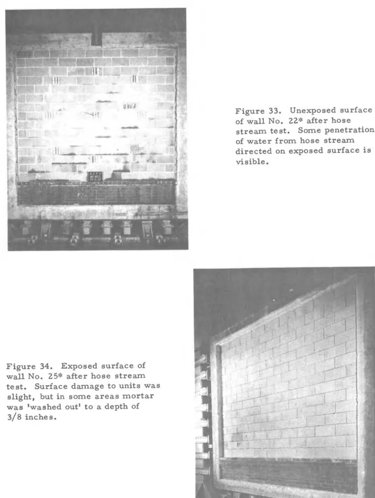
Immediately following f i r e exposure standard t e s t walls were subjected to a hose s t r e a m played directly on the fire-exposed f a c e of the t e s t specimens. The duration of application of the hose s t r e a m and the nozzle p r e s s u r e were determined f r o m the length of f i r e exposure
in accordance with El 19. All of the 16 standard t e s t walls successfully
withstood the impact and erosion effects of the hose s t r e a m test. At no time during o r after f i r e exposure was the s t r u c t u r a l integrity of the
walls threatened a s evidenced by the degree of difficulty experienced in
removing walls f r o m the restraining f r a m e subsequent to test.
Throughout f i r e exposure and subsequent to the hose s t r e a m test,
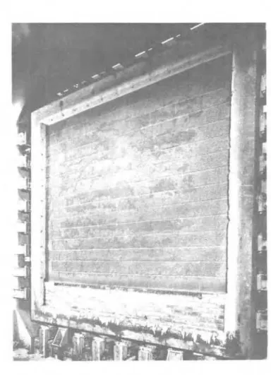
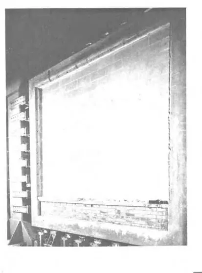
numerous observations were made of the physical behaviour of each standard t e s t wall. As expected, a wide range of performance under f i r e was observed. P a r t i c u l a r l y detrimental t o exposed surfaces of walls was the shock, impact and erosion effects of the hose s t r e a m played directly onto the hot surface of walls when their 'fire endurance
to units was visible while for some walls, extensive surface crazing, l o s s of small amounts of m o r t a r between joints o r physical disintegration of portions of some units, to a depth of 1/8 inch could be observed.
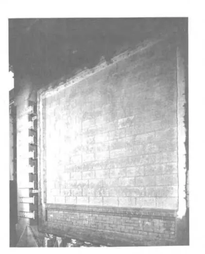
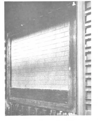
F i g u r e s 23 to 48 show the condition of certain t e s t walls a t various stages of the f i r e test; included a r e representative observations within the range of performance of the tested units.
F i r e Endurance of Masonry a s Affected by Aggregate Type, Thickness and Moisture
The mineralogical composition of the aggregates in units of t e s t walls and panels had a decisive effect on the performance i n fire. The thermal conductivity of cement paste i s not subject to l a r g e variations and it is primarily the t h e r m a l conductivity of the aggregates that will determine the insulating quality of the concrete. Owing t o t h e i r
amorphous structure and partly to their high porosities (and consequently low t h e r m a l conductivities) lightweight aggregates exhibit better insulat- ing qualities than do normal weight aggregates.
Concrete masonry units made with lightweight aggregates appear to have particular m e r i t with regard to f i r e resistance, a s evidenced by the r e s u l t s of the many f i r e t e s t s c a r r i e d out in this program. Owing to the initial 'heat treatment' of these aggregates during t h e i r manufacture, they usually exhibit good stability during exposure t o high t e m p e r a t u r e s
.
Although it i s recognized that variations i n composition and structure within a particular aggregate group will affect performance i n f i r e , the r e s u l t s of this program, generally demonstrated the superior performance of units made with lightweight aggregates.
F i g u r e s 49 to 54 present graphically r e s u l t s of the sixty f i r e t e s t s c a r r i e d out involving units of two normal weight and four lightweight aggregate groups. Each figure illustrates the functional relationship obtained between experimental f i r e endurance periods and equivalent
thickness f o r masonry units of a particular aggregate grou
.
Thiswhere
F
= f i r e enduranceT
= equivalent thicknessA and N = constants f o r a given aggregate group. No attempt, however, has been made t o determine values of A and N i n each case since the data shown include r e s u l t s of both standard and
s m a l l panel t e s t s a s well a s those t e s t s c a r r i e d out specifically t o determine the effect of plaster protection or sand replacement on f i r e endurance.
The f i g u r e s do indicate, generally, that the f i r e endurance of unit masonry i s a function p r i m a r i l y of aggregate type and equivalent thickness.
The performarrce of siliceous gravel masonry units during f i r e exposure was generally not inferior to that of calcareous aggregate units. The t h e r m a l conductivity of the f o r m e r i s not n e c e s s a r i l y higher than that of the calcareous aggregate units since, in addition t o the mineralogical composition, the degree of crystallinity of the a g g r e - gate will influence i t s t h e r m a l conductivity. Some r e s e a r c h e r s have observed a tendency for highly siliceous aggregates t o undergo explosive disruption during exposure to high t e m p e r a t u r e s , presumably due t o the
a -.
B
transformation of quarto. This change of phase occurs at approx- imately 573°C with an accompanying change in the volume of the aggregate. If the induced s t r e s s e s within the s t r u c t u r e of the m a t e r i a l cannot berelieved or absorbed within the cement-aggregate matrix, physical disruption (spalling) of exterior surfaces may occur. While the silica content of aggregates in the siliceous gravel units subjected t o f i r e ex- posure in t h i s program was extremely high (Table A l ) , it is noteworthy that no 'spalling' of t h e s e units was observed during f i r e exposure of
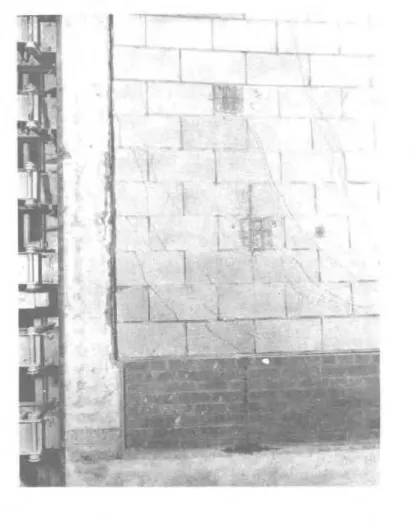
either standard or s m a l l panel specimens. As indicated in Figures 36 and 37, however, extensive diagonal and vertical cracking near p e r i m e t e r a r e a s of a standard t e s t wall was observed after approximately 30 minutes of f i r e exposure.
The effect of cavities in hollow concrete m a s o n r y on performance in f i r e was studied through a number of s m a l l panel t e s t s on 4- and
of each of the six types of aggregates. In the c a s e of siliceous and
calcareous aggregate units, performance in f i r e of hollow units appeared superior to that of the solid masonry. Conversely, for lightweight
aggregate units, Figure 55 indicates relatively better performance in f i r e for solid masonry units. The data a r e not sufficient, however, t o claim that a s i m i l a r relationship between equivalent thickness and f i r e endurance for hollow and solid m a s o n r y would be obtained in each c a s e if the range of data was extended. On the other hand, the information obtained does suggest that the presence of 'air gaps' or cavities in m a s o n r y will affect performance in f i r e . F r o m the point of view of f i r e endurance, the presence of a i r gaps appears beneficial for n o r m a l weight aggregate units but not in the c a s e of lightweight aggregate units.
*
It would be expected that the relative i n c r e a s e in insulation value afforded by a i r gaps would properly be a function of the insulating quality of the concrete itself.Some r e s e a r c h e r s have also suggested that the f i r e endurance of concrete may be expressed a s a function of concrete density. Since, in this program, the density of concrete f o r the various m a s o n r y units varied over a wide range, it was possible t o observe the effect on f i r e endurance. Figure 56 shows the relationships obtained between f i r e endurance and concrete density for four and six inch m a s o n r y units of various equivalent thicknesses. The data shown include r e s u l t s of
s m a l l panel t e s t s only f o r which m a s o n r y units w e r e low p r e s s u r e cured. No data have been included f r o m t e s t s on plastered panels, but data a r e shown f o r t e s t s involving partially sanded lightweight units. As can be seen it was not possible t o express f i r e endurance a s a function of
concrete density in relation t o any specifically selected s e t of equivalent thickness values (again the u s e of some method other than ASTM C140 t o m e a s u r e equivalent thickness of units m a y have provided m o r e consistent data). It was possible, however, to e x p r e s s the relationship in t e r m s of
*
Equivalent thickness values of lightweight aggregate m a s o n r y units w e r e found, generally, to be lower than those of geometrically s i m i l a r units made with n o r m a l weight aggregates. Strictly speaking, the u s e of some method other than ASTM C140 t o m e a s u r e net volume of the units (i. e. sand replacement) m a y indicate a m o r e congruous relation- ship between the performance in f i r e of comparable hollow and solid units of the s a m e equivalent thickness.s i z e ( 4 o r 6 inch) and geometry ( hollow o r solid) of the units a s shown in Figure 56. Generally, the data support the findings of other r e s e a r c h e r s
in that an i n v e r s e functional relationship m a y be assumed between f i r e endurance and the density of concrete f r o m which a given m a s o n r y unit i s made.
F i g u r e 57 shows the i n c r e a s e in f i r e endurance of concrete m a s o n r y units which m a y be expected due to the beneficial effects of m o i s t u r e in specimens at the t i m e of t e s t . Calculation of f i r e endurance periods, a t a theoretical level of ' z e r o m o i s t u r e content' h a s a l r e a d y been discussed and percentage i n c r e a s e s in experimental f i r e endurance periods of specimens due to m o i s t u r e a r e shown in the figure. T h e data shown include r e s u l t s of a l l 60 f i r e t e s t s c a r r i e d out in t h e program. Equations of 'line of best fit' t o e x p r e s s the gain in f i r e endurance due t o a volumetric m o i s t u r e content of 1 p e r cent at the t i m e of t e s t have been developed for both n o r m a l weight and lightweight m a s o n r y units. As indicated, an i n c r e a s e of approximately 5. 62 p e r cent in the f i r e
endurance of lightweight units m a y be expected for each percentage of m o i s t u r e , by volume. F o r n o r m a l weight units, each percentage of m o i s t u r e , by volume at the t i m e of t e s t m a y be expected t o i n c r e a s e the f i r e endurance by about 4.05 p e r cent.
I n c r e a s e in F i r e Endurance of Concrete Masonry due t o P l a s t e r
P l a s t e r e d walls and panels withstood longer f i r e exposures than s i m i l a r unplastered specimens b e f o r e limiting t e m p e r a t u r e s on the
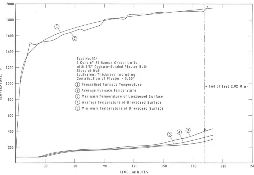
unexposed surface w e r e exceeded. T h e contribution of p l a s t e r protection in increasing the f i r e endurance of various walls and panels i s illustrated in F i g u r e 58. Only 1 s e t of identical standard s i z e walls was built f o r f i r e testing with and without p l a s t e r protection. T e s t wall No. 16'k
(6-in. hollow siliceous gravel units) with no p l a s t e r protection had a f i r e endurance of 1. 55 h r . The addition of 5/8 -in. gypsum -sanded p l a s t e r
t o both s i d e s of an identical t e s t wall (No. 31*) i n c r e a s e d the f i r e endurance period by n e a r l y 107 p e r cent t o 3. 2 h r . (The ' d r y t h e r m a l f i r e endurance' by comparison was i n c r e a s e d from 1. 23 t o 2.97 h r . )
F i r e endurance periods of s m a l l panel 'wallettes' w e r e a l s o
i n c r e a s e d considerably by the addition of p l a s t e r . Ten t e s t s w e r e c a r r i e d out in which 5 types of wallettes w e r e exposed to f i r e with and without
p l a s t e r protection. F i g u r e 58 indicates the gain in f i r e endurance f o r r e s p e c t i v e p a i r s of p l a s t e r e d and unplastered comparison specimens ranged from about 69 p e r cent (for 6-in. hollow expanded slag units)
t o 120 p e r cent (for 4-in. hollow pumice aggregate units). Corresponding i n c r e a s e s in t e r m s of the ' d r y calculated values' a r e a l s o shown.
In calculating the equivalent thickness of p l a s t e r e d specimens, the contribution of the p l a s t e r finish was determined in accordance with provisions of Supplement No. 2 t o the National Building Code of Canada. T h e t r u e thickness i s multiplied by a factor depending on the type of unit t o which the p l a s t e r i s applied (for gypsum sand p l a s t e r , t h e s e f a c t o r s a r e 1. 50, 1. 25, and 1. 00 f o r type S, type N, and type L m a s o n r y units respectively a s described in Supplement No. 2 ) . T h e c o r r e c t e d thickness i s then included in the equivalent thickness. Using this method, the
percentage i n c r e a s e s in f i r e endurance for the p l a s t e r e d specimens
r e l a t i v e t o companion unplastered specimens w e r e calculated and compared to r e s p e c t i v e i n c r e a s e s in f i r e endurance due to p l a s t e r r e c o r d e d in the t e s t s . Agreement observed was generally good. F o r s m a l l panel t e s t s
of siliceous gravel, calcareous aggregate, expanded slag, expanded shale and pumice aggregate units calculated i n c r e a s e s in f i r e endurance w e r e 108, 100, 79, 80, and 96 p e r cent respectively. Corresponding i n c r e a s e s r e c o r d e d in the t e s t s w e r e 93, 91, 69, 85 and 120 p e r cent respectively.
The application of p l a s t e r protection, besides increasing the thickness of the wall and improving i t s insulation, a l s o h a s the effect
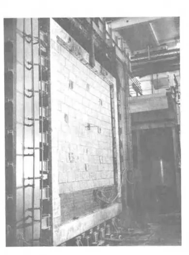
of reducing t h e t h e r m a l shock to which t h e blocks a r e subjected in the t e s t . Gypsum-sanded p l a s t e r applied directly to s u r f a c e s of blocks, however, cannot always be r e l i e d upon to r e t a i n i t s adhesion under f i r e
conditions. Observations taken on a standard t e s t wall ( F i g u r e 41) of 6 -in. hollow siliceous gravel units during f i r e exposure indicated that the finish coat of p l a s t e r began t o f a l l off in s o m e a r e a s 10 minutes
after the t e s t s t a r t e d . Brown and s c r a t c h coats of p l a s t e r , however, remained intact until the end OX f i r e exposure, 3 h r and 2 minutes l a t e r . A l l t h r e e coats of p l a s t e r w e r e completely destroyed over the e n t i r e wall by the h o s e s t r eam t e s t ( F i g u r e 42). In another t e s t of 4-in. hollow pumice aggregate units ( F i g u r e 44), the finish coat was destroyed in one a r e a after 15 minutes of f i r e exposure and after 47 minutes brown and s c r a t c h coats in this a r e a fell off. S e v e r e cracking l a t e r developed on the exposed f a c e s of units ( F i g u r e 46). After the h o s e s t r e a m t e s t , no p l a s t e r could be s e e n intact on any p a r t of the wall.
P l a s t e r on s m a l l panel wallettes appeared l e s s affected by f i r e exposure. T h e i n c r e a s e d dead weight of p l a s t e r on standard s i z e walls appeared in p a r t responsible for 'map cracking' of the p l a s t e r during f i r e exposure since only after v e r y long exposure periods was any
random cracking observed in p l a s t e r of s m a l l panel specimens. In none of t h e t e s t s on wallettes was the brown o r s c r a t c h coat of p l a s t e r on t h e exposed face damaged appreciably during f i r e exposure.
Generally, the r e s u l t s indicate that gypsum p l a s t e r will provide an effective b a r r i e r to heat flow during exposure t o f i r e . This i s
principally due to i t s high heat absorption during the dehydration p r o c e s s . T h e additional protection against f i r e provided by t h e p l a s t e r would s e e m t o be a function of both wall s i z e and the ability of the p l a s t e r t o r e m a i n intact during f i r e exposure.
Effect of Sand Replacement on the F i r e Endurance of Lightweight Concrete Masonrv Units
In recognition of the general u s e of sand replacement of light
-
weight aggregate, a limited s e r i e s of t e s t s was c a r r i e d out t o study the relationship between the percentage replacement of sand (by volume) and f i r e endurance for various lightweight aggregate m a s o n r y units. T h r e e 2;- by 2;-ft t e s t panels w e r e built from units of each of thefollowing types of aggregates: expanded slag, expanded shale, expanded clay and pumice. T h e f i r s t group of panels consisted of units in which the aggregate was 100 p e r cent lightweight m a t e r i a l . In t h e second
group approximately 10 p e r cent of the lightweight aggregate f o r the units was replaced with n a t u r a l sand, and in the t h i r d group, the volume replacement of lightweight m a t e r i a l was approximately 20 per cent. P a n e l s w e r e subjected t o f i r e exposure t o c o m p a r e the p e r f o r m a n c e of 'pure' lightweight aggregate m a s o n r y units with that of companion 'sanded' units.
Data on a v e r a g e concrete density and 28-day c o m p r e s s i v e strength for the units along with r e c o r d e d f i r e endurance periods f o r r e s p e c t i v e panels a r e shown graphically in F i g u r e 59. Generally, it m a y be s e e n that a s average c o n c r e t e densities i n c r e a s e d ( o r d e c r e a s e d ) with increasing percentages of sand replacement, the c o m p r e s s i v e strength of the units varied correspondingly but t o a l e s s e r degree. T h e notable exception t o this behaviour was observed for expanded clay aggregate
units in which increasing concrete densities for the sanded units r e s u l t e d i n a d e c r e a s e , r a t h e r than an i n c r e a s e in strength. F i r e endurance
p e r i o d s of panels generally d e c r e a s e d slightly with i n c r e a s i n g percentages of n a t u r a l sand. A notable exception t o this is panels m a d e with pumice aggregate units for which increasing the n a t u r a l sand content (up t o a
maximum of 24.8 p e r cent by volume) r e s u l t e d in improved performance under fire.
It i s difficult to attempt a meaningful interpretation of the data f r o m which to r e l a t e the f i r e endurance of lightweight aggregate m a s o n r y units t o the total volume percentages of lightweight m a t e r i a l and n a t u r a l sand. T h e t e s t panels themselves w e r e built f r o m units provided by a number of manufacturers whose production m a t e r i a l s and techniques m a y have differed consider ably. F o r example, t h r e e different r e p l a c e
-
ment sands w e r e used in the production of the four types of sanded units, each having i t s own c h a r a c t e r i s t i c gradation, unit weight, and mineralogical com.position. (Replacement sands for units of expanded slag,expanded shale and pumice aggregate w e r e predominantly siliceous m a t e r i a l with fineness moduli of 1. 54, 1. 54 and 1. 16 respectively. Material for sanded expanded clay units, on the other hand, was a c a l c a r e o u s concrete sand having a fineness modulus of 2 . 6 ) . The different conditions under which the units w e r e cured, s t o r e d and subsequently shipped by the r e s p e c t i v e p r o d u c e r s a l s o m a k e s it difficult t o a s s e s s the validity of the r e s u l t s . T h e relationships between strength, density and f i r e endurance for r e s p e c t i v e p u r e and sanded lightweight units shown in F i g u r e 59 m a y not be e n t i r e l y r e p r e s e n t a t i v e of those which might be derived under m o r e s t r i c t l a b o r a t o r y conditions.
Nevertheless, the slight d e c r e a s e in f i r e endurance observed for 3 of the 4 types of 'sanded' lightweight units a s compared with that for companion 'pure' lightweight units would be expected. T h e addition of sand, a m a t e r i a l of higher t h e r m a l conductivity, r e p l a c e s p a r t of the lightweight aggregate of lower t h e r m a l conductivity. The conductivity of t h e combined s a m p l e would be proportional t o the volume percentages of the lightweight aggregate and n a t u r a l sand in the resulting mixture.
Since the percentage of sand is much lower only a slight increase in the t h e r m a l conductivity of the 'sanded' units would be expected, leading
to proportionately slight d e c r e a s e s in the f i r e endurance of such units.
*
A detailed investigation into the elevated temperature properties (conductivity, diffusivity and specific heat) of the tested units i s underway. Knowledge of the variation of these properties with temperature i s needed to l e a r n m o r e about the effect of sand replacement on the f i r e endurance of lightweight concrete masonry units.
Comparison of F i r e Endurances f r o m T e s t s on 'Small Panels1 with those obtained f r o m 'Standard' F i r e Test Specimens
Since 22- by 2;-ft specimens w e r e used extensively i n the
program, it is of i n t e r e s t to compare t h e i r f i r e endurances with those of
companion specimens of standard size (10 by 12 ft). Figure 60 shows
this comparison f o r both experimental f i r e endurance periods and the
d r y 'calculated1 values, i. e. endurance periods obtained a f t e r
compensating for the beneficial effects of moisture on f i r e endurance. F o r 10 of the 16 'sets1 of comparative tests, higher f i r e endurance periods w e r e recorded f o r 22- by 22-ft specimens than f o r 'standard' size specimens; in only 2 c a s e s were equal f i r e endurance periods obtained in t e s t s of s i m i l a r constructions. After correcting f o r moisture, 'dry8 f i r e endurance periods were found to be higher f o r t e s t s of small panels in 12 of the 16 cases. Correlation between
r e s u l t s of s m a l l panel and standard t e s t s ranged f r o m good f o r speci- m e n s of expanded slag, expanded shale and expanded clay aggregate
*
This explanation is necessarily an over-simplification of a complexproblem
-
that of estimating the t h e r m a l conductivity of two-phasemedia. "The effective t h e r m a l conductivity of a sample composed of m o r e than one phase m u s t be related t o the t h e r m a l conductivities of the separate components a s well a s the detailed s t r u c t u r e of the aggregate. The individual regions of each phase a r e assumed sufficiently l a r g e that they m a y be characterized by the t h e r m a l conductivity of that component, yet sufficiently small in comparison with the total volume of the sample that the s m a l l scale behaviour of individual regions m a y be ignored. F o r porous media, the detailed structure i s of considerable importance in determining the t h e r m a l conductivity. Completely general predictions of t h e r m a l conductivity cannot be made unless some knowledge of the degree of continuity of
to poor in the case of specimens made with pumice aggregate units; correlation for tests of siliceous and calcareous aggregate units was intermediate. The reproducibility of f i r e test results (for small panel specimens) was demonstrated by three identical tests involving
calcareous aggregate units (tests Nos, 12, 12A and 12B). The variation in f i r e endurance periods recorded f o r these panels was l e s s than 6 per cent.
Generally, the results of this s e r i e s of tests suggest that, in addition to other factors, the material properties of the masonry units themselves (as determined primarily by the type of aggregate), may influence the agreement in results obtained from a small panel and
standard f i r e test on a similar construction.
The single most important factor responsible for the increase in thermal f i r e endurance observed in small panel tests i s believed to be related directly to size effects rather than to differences in furnace design, although this and other such considerations may be significant. In the small panel tests there i s probably a substantial amount of lateral heat flow in relation to the surface a r e a of the test specimen exposed to fire, whereas the heat flow pattern in standard tests i s predominately unidimensional and perpendicular to the test specimen. The effectiveness of insulation in preventing heat l o s s from around perimeter a r e a s of
standard and small panel test specimens would probably influence heat transfer to the exposed face, The fact that the standard f i r e furnace i s of the gas-fired type and operates under negative pressure while the small panel furnace i s heated electrically may also influence the mechanism of heat transfer within the furnace atmosphere.
A multiple regression analysis of the test data to study the relationship of specimen size on f i r e endurance i s underway; the results will be reported at a later date.
F i r e Endurance of Autoclaved vs Low P r e s s u r e Cured Masonry Units Table 20 shows data on four small panel tests in which the f i r e endurances of low pressure cured units a r e compared with those of companion autoclaved units. In the f i r s t set of t e s t s (Nos. 14 and 27) similar aggregate gradations and manufacturing procedures were used but mix proportions varied slightly. (Silica flour was used in the
production of autoclaved units and proportions of aggregate and cement were adjusted accordingly. ) Similarly, units for tests Nos. 18 and 28 were identical in every respect except f o r slight differences in mix
proportions (Table 13). The time required f o r the unexposed surfaces of each panel to exceed both the average and maximum permissible r i s e above ambient temperature a s well a s d r y (calculated) endurance
periods a r e shown in the table.
F o r panels made f r o m expanded slag aggregate, autoclaved units had slightly l a r g e r values of equivalent thickness but withstood f i r e exposure f o r 8 minutes l e s s than companion low p r e s s u r e cured units before the maximum r i s e of temperature terminated the f i r e endurance. F o r panels of siliceous gravel aggregate, equivalent thickness values of autoclaved units were slightly lower than f o r comparable low p r e s s u r e cured specimens and again a lower f i r e endurance period was recorded f o r the t e s t panel of autoclaved units. F a i l u r e of siliceous gravel panels, however, was due to average temperature r i s e of the unexposed surface.
The limited number of t e s t s c a r r i e d out makes it difficult t o evaluate the relative m e r i t s of autoclaving vs low p r e s s u r e curing of masonry units a s r e g a r d s performance in fire.
Theoretically, the p r o c e s s of autoclaving develops a m o r e
'crystalline' structure within the concrete and the degree of crystallinity of m a t e r i a l s i s an important factor i n their t h e r m a l conductivity. Highly crystalline m a t e r i a l s will exhibit higher t h e r m a l conductivities a t room temperature* than those having predominantly amorphous m i c r o s t r u c t u r e s ,
i. e. a very low degree of crystallinity. A s the t h e r m a l conductivity of autoclaved units would be expected to be higher than that of companion low p r e s s u r e cured units, slightly lower f i r e endurance periods might be expected in the c a s e of the autoclaved units.
The r e s u l t s of t e s t s Nos. 18 and 28 tend to confirm the theory in that, f o r a given value of equivalent thickness, low p r e s s u r e cured expanded slag aggregate units behaved better under f i r e exposure than comparable autoclaved units. Data f r o m t e s t s NOS. 14 and 27 also tend t o support the theory but the evidence is l e s s conclusive. Strictly
speaking, valid experimental confirmation of the theory would be difficult to achieve since it i s not practical to produce both low p r e s s u r e cured and autoclaved units with identical m i x compositions.
. - -
*
Strictly speaking, highly crystalline mixture s exhibit relatively high conductivities at room temperature and gradually decreasingconductivities at increasing temperatures. The conductivity of
amorphous formations, on the other hand, i s low a t room temperature, relatively insensitive to chemical composition, and i n c r e a s e s slightly with an i n c r e a s e i n temperature.
F i r e Endurance of Walls built with 2- and 3-Core Concrete Masonry Units
Table 21 shows data on four small panel t e s t s in which the f i r e endurances of two core units a r e compared with those obtained f r o m t e s t s of comparable t h r e e core units. In t e s t s Nos. 10 and 29, s i m i l a r aggregate gradations, m i x proportions and manufacturing methods were used f o r both the 2- and 3-core units. Expanded shale aggregate units f o r t e s t s Nos. 21 and 30 were also identical in every r e s p e c t except f o r the number and arrangement of c o r e spaces.
Although f i r e endurance periods were determined by either average o r maximum r i s e at a single point above the ambient tempera- ture, whichever occurred f i r s t , the time required f o r each panel to m e e t both of these failure c r i t e r i a has been shown. The actual f i r e
endurance period i n each case has also been corrected for the beneficial effects of moisture and the d r y (calculated) values have been included i n the table.
It may be noted that f i r e endurance periods of 2-core units ( t e s t s Nos. 10 and 21) were determined by maximum r i s e of temperature a t a single point on the unexposed surface while those of 3-core units ( t e s t s Nos. 29 and 30) were determined by average r i s e of temperature a b m e ambient. This finding, however, may not be considered significant. In both c a s e s where f i r e endurance periods were terminated due to maximum r i s e of temperature, such t e m p e r a t u r e s were recorded by thermocouples located adjacent to cavity a r e a s r a t h e r than over web portions of units. Measurements made on respective s e t s of 2- and
3-core units indicated over-all thickness, minimum face shell dimensions and minimum web thicknesses were approximately equal f o r s i m i l a r 2- and 3 -core units providing almost identical heat flow paths through sections where failure (due t o maximum temperature r i s e for 2-core units and average temperature r i s e f o r 3-core units) occurred. In addition, a review of tables 14 through 19 will indicate that f i r e endurances of s e v e r a l 2-core masonry panels were determined by average r i s e r a t h e r than maximum r i s e of temperature above ambient.
Values of equivalent web thickness* f o r 2- and 3- core units varied f r o m 2.75 in. to 3.43 in. but it i s not possible to a s c e r t a i n f r o m
*
Equivalent web thickness i s defined a s the sum of measured thickness of a l l webs in unit, t i m e s 12, divided by length of unit.the data what effect this variation may have i n relation to performance in fire. The locations in which thermocouples a r e positioned on the unexposed surface, i. e. whether placed adjacent t o cavity o r over web a r e a s of blocks would influence the mode of failure, i. e. by average o r maximum r i s e of temperature and hence the f i r e endurance. As would be expected, temperatures recorded by thermocouples located adjacent to web a r e a s consistently lagged those recorded by thermocouples placed adjacent to cavity a r e a s .
The data i n Table 21 suggest that, f o r units containing the s a m e percentage of solid concrete of a given type and density, the f i r e en- durance will be slightly longer f o r 3-core units than for units having only 2 cores. The data a r e too meagre, however, to substantiate that the number and arrangement of c o r e spaces i n a masonry unit will
significantly affect the f i r e endurance of walls built with such units. SUMMARY
F i r e t e s t s have been c a r r i e d out on 37 different types of concrete masonry units. Sixty t e s t specimens, 44 of which m e a s u r e d 2 i by 2 i f t and the remainder 10 by 12 f t , were constructed and subjected to f i r e exposure. Results of the t e s t s a r e presented i n tables 14 to 19 and
figures 49 to 54. On the basis of the results, the following general
comments m a y be made.
1. The f i r e endurance of concrete masonry units would s e e m to be a function primarily of aggregate type, thickness and moisture content. The functional dependence of f i r e endurance on each of these p a r a m e t e r s does not appear to be uniquely defined owing to the variable influence of and possible interaction affects among these parameters.
2. The performance of highly siliceous gravel units i n f i r e is not necessarily inferior to that of calcareous aggregate units. F i r e
endurance periods of specimens built f r o m units of each aggregate type were approximately equal but behaviour of siliceous gravel specimens i n f i r e was characterized by considerable diagonal and vertical crack- ing.
3. The d i r e c t application of gypsum-sanded plaster t o concrete masonry surfaces m a y be expected t o substantially i n c r e a s e the f i r e
endurance, provided good adhesion to m a s o n r y i s attained and p l a s t e r remains intact during f i r e exposure.