Characterization of onset of parametric
decay instability of lower hybrid waves
The MIT Faculty has made this article openly available.
Please share
how this access benefits you. Your story matters.
Citation
Baek, S. G., P. T. Bonoli, R. R. Parker, S. Shiraiwa, G. M. Wallace, M.
Porkolab, Y. Takase, et al. “Characterization of Onset of Parametric
Decay Instability of Lower Hybrid Waves” (2014).
As Published
http://dx.doi.org/10.1063/1.4864510
Publisher
American Institute of Physics (AIP)
Version
Author's final manuscript
Citable link
http://hdl.handle.net/1721.1/88533
Terms of Use
Creative Commons Attribution-Noncommercial-Share Alike
June 2013
Plasma Science and Fusion Center
Massachusetts Institute of Technology
Cambridge MA 02139 USA
This work was supported by the U.S. Department of Energy, Grants No.
DE-FC02-99ER54512 and DE-AC02-76CH03073. Reproduction, translation,
publication, use and disposal, in whole or in part, by or for the United States government
is permitted.
PSFC/JA-13-30
Characterization of Onset of Parametric Decay
Instability of Lower Hybrid Waves
S. G. Baek, P. T. Bonoli, R. R. Parker, S. Shiraiwa, G. M. Wallace,
M. Porkolab, Y. Takase*, D. Brunner, I. C. Faust, A. E. Hubbard,
B. L. LaBombard, and C. Lau
Characterization of Onset of Parametric Decay Instability of
Lower Hybrid Waves
S. G. Baek
∗, P. T. Bonoli
∗, R. R. Parker
∗, S. Shiraiwa
∗, G. M. Wallace
∗, M.
Porkolab
∗, Y. Takase
†, D. Brunner
∗, I. C. Faust
∗, A. E. Hubbard
∗, B. L. LaBombard
∗and C. Lau
∗∗MIT Plasma Science and Fusion Center, Cambridge, MA
†The University of Tokyo, Kashiwa, Japan
Abstract. The goal of the lower hybrid current drive (LHCD) program on Alcator C-Mod is to develop and optimize ITER-relevant steady-state plasmas by controlling the current density profile. Using a 4x16 waveguide array, over 1 MW of LH power at 4.6 GHz has been successfully coupled to the plasmas. However, current drive efficiency precipitously drops as the line averaged density (ne) increases above 1020m−3. Previous numerical work shows that the observed loss of current
drive efficiency in high density plasmas stems from the interactions of LH waves with edge/scrape-off layer (SOL) plasmas [Wallace et al., Physics of Plasmas 19, 062505 (2012)]. Recent observations of parametric decay instability (PDI) suggest that non-linear effects should be also taken into account to fully characterize the parasitic loss mechanisms [Baek et al., Plasma Phys. Control Fusion 55, 052001 (2013)]. In particular, magnetic configuration dependent ion cyclotron PDIs are observed using the probes near ne≈ 1.2 × 10²⁰m−3. In upper single null plasmas, ion cyclotron PDI is excited near the low field side
separatrix with no apparent indications of pump depletion. The observed ion cyclotron PDI becomes weaker in inner wall limited plasmas, which exhibit enhanced current drive effects. In lower single null plasmas, the dominant ion cyclotron PDI is excited near the high field side (HFS) separatrix. In this case, the onset of PDI is correlated with the decrease in pump power, indicating that pump wave power propagates to the HFS and is absorbed locally near the HFS separatrix. Comparing the observed spectra with the homogeneous growth rate calculation indicates that the observed ion cyclotron instability is excited near the plasma periphery. The incident pump power density is high enough to overcome the collisional homogeneous threshold. For C-Mod plasma parameters, the growth rate of ion sound quasi-modes is found to be typically smaller by an order of magnitude than that of ion cyclotron quasi-modes. When considering the convective threshold near the plasma edge, convective growth due to parallel coupling rather than perpendicular coupling is likely to be responsible for the observed strength of the sidebands.To demonstrate the improved LHCD efficiency in high density plasmas, an additional launcher has been designed. In conjunction with the existing launcher, this new launcher will allow access to an ITER-like high single pass absorption regime, replicating the JLH(r) expected in ITER. The predictions from the time domain discharge scenarios, in
which the two launchers are used, will be also presented. Keywords: lower hybrid, current drive, parametric decay instability PACS: <52.35.Hr, 52.55.Wq>
INTRODUCTION
The main motivation of lower hybrid current drive (LHCD) experiments on Alcator C-Mod [1] is to actively control the current density profile to develop ITER relevant steady state regimes. Lower hybrid (LH) waves can transfer their momentum and energy to resonant electrons, resulting in net plasma current. The use of LH waves in driving off-axis current is known to be among the most efficient existing current drive system. Thus, LHCD can provide an effective tool to broaden the current density profile and optimize the shear profile in achieving advanced tokamak (AT) operation. The steady state AT operation scenarios developed in Alcator C-Mod are expected to be relevant and readily applicable to ITER because both magnetic field and density in Alcator C-Mod, which primarily determine LH wave propagation behavior, are similar to ITER. In addition, the LHCD frequency and diverted plasma configuration are also similar to those of ITER.
A previous scoping study [2] with Alcator C-Mod plasma parameters indicated that a majority of plasma current
can be sustained by the naturally occurring pressure driven bootstrap current in high temperature (Te0≈ 5keV), high
density (ne≈ 1.5 × 10²⁰m−3) plasmas. It was identified that 3 MW of LHCD can supplement the bootstrap current at
the outer radial region with on-axis fast wave current drive to eliminate the need for inductive plasma current. High density plasmas were found to be necessary to ensure not only good confinement but also a significant amount of
Collisional Loss ne (1020 m-3) (s-1) 107 106 0.6 105 103 104 0.8 1.0 1.2 1.4 1.6 0.4
Line Integrated HXR Count Rate
-Experiment
Simulation w/ no Edge Effects
Is discrepancy due to non-linear effects ?
Full wave
FIGURE 1. Measured non-thermal hard X-ray count rate as a function of ne (green). Over-plotted are
pre-dicted non-thermal hard X-ray count rate from GENRAY-CQL3D (blue) and LHEAF (purple), both of which
intro-duce additional parasitic edge effects. FIGURE 2. LH launcher on Alcator C-Mod
bootstrap current fraction (& 50 %), which is critical for achieving steady state tokamak operation.
Nonetheless, high density LHCD experiments on Alcator C-Mod have revealed a loss of current drive efficiency [3, 4]. In low density plasmas, fully non-inductive plasma discharges [5] were demonstrated with engineering efficiency
η≡ n20IR/P≈ 0.25A/mW2, consistent with expected efficiency based on theory. However, when neis raised above
1.0× 10²⁰m−3, all experimental signatures of current drive effect disappear. It was found that collisional absorption
at the edge can reduce effective LH power and full-wave effects can excessively up-shift the parallel refractive index
(n∥) of LH waves, both of which can reduce the amount of driven current ( jlh∝ P/(nen2∥)). Nonetheless, there remains
a discrepancy between simulations and experiments by an order of magnitude when comparing the level of
non-thermal hard X-ray count rate above ne≈ 1.0 × 10²⁰m−3, as shown in Figure 1. Because the discrepancy between the
experiments and simulations is seen only in high density plasmas, in the recent campaign, we have examined density-dependent loss mechanisms such as spectral broadening and parametric decay instability[6, 7, 8], which can reduce
effective pump power and result in higher n∥at the same time.
The purpose of this paper is to understand the observed onset of PDI, which may form another significant power loss
channel in high density plasmas. PDI is found to be excited when ne& 1.0 × 10²⁰m−3, a regime where simulations
predict the higher level of non-thermal hard X-rays as compared to experimental results. While previous studies [8, 9] focused on PDI possibly happening near a launcher in much higher density plasmas, our recent experimental results [10] show that PDI at the plasma edge, away from the launcher, can be excited as well in a multi-pass regime.
The observed PDI shows a magnetic configuration dependency in high density plasmas (ne≈ 1.2×10²⁰m−3). In lower
single null (LSN) plasmas, PDI is found to be excited at the HFS edge (HFS PDI) whereas in upper single null (USN) plasmas, PDI is excited at the low field side (LFS PDI) edge. In this paper, we will not attempt to explain mechanisms that can result in different kinds of PDI depending on magnetic configurations. We will rather attempt to identify mechanisms that can lead to HFS PDI by examining the homogeneous growth rate and convective growth.
LHCD SYSTEM OF ALCATOR C-MOD
The LHCD system of Alcator C-Mod uses a waveguide grill antenna to couple slow LH waves at 4.6 GHz, as shown in Figure 2. This launcher has been installed on Alcator C-Mod since the 2010 campaign and has been reliable in the past three years of physics operations. A set of klystrons provides 3 MW of source power. Standard WR-187 waveguides are used to feed source power to the launcher, which consists of 4 rows of 16 active waveguides. The
dimension of each waveguide is 7× 60mm. A four-way splitter system at the front end of the LHCD system splits
power evenly into each row of waveguides and increases transmission efficiency up to∼ 75%, as compared to the
previously installed launcher with the transmission efficiency up to 50% at best [11]. Another resulting feature is that the launcher is resilient to poloidal variations in plasma loading. Using this system, the launched antenna spectrum can
DC Output RF (~ 4.6 GHz) LO Variable LO Amplifier Low Pass Filter Power Detector (3.5 GHz) (~ 1.1 GHz) LSN USN HFS Probe
(Inner Wall Probe)
Outer Divertor Probe LFS Probe (Probe on the LH launcher) Limiter LH Ray (1020 m-3) Frequency (GHz) Time (Sec)
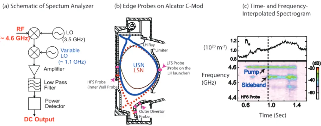
(a) Schematic of Spectum Analyzer (b) Edge Probes on Alcator C-Mod (c) Time- and
Frequency-Interpolated Spectrogram
FIGURE 3. (a) A schematic of spectrum analyzer. (b) Poloidal cross-section of Alcator C-Mod and the location of the probes. (c) An example of time- and frequency- interpolated spectrogram.
has been coupled to the plasmas with a wide range of magnetic fields (3∼ 8T), densities (ne= 0.3∼ 2 × 10²⁰m−3),
and plasma currents (300∼ 1000kA). A recent upgrade of the transmitter protection system has also allowed the pulse
length to be extended up to 1 second [12].
EXPERIMENTAL SETUP
To continuously monitor LH frequency spectra in a single plasma discharge at the various locations simultaneously, multi-channel spectrum analyzers have been developed. Figure 3(a) shows the schematic diagram of the developed heterodyne detection system. Input signals around at 4.6 GHz are first down-converted to 1.1 GHz by a fixed local oscillator (LO). At the second mixing stage, by controlling the frequency of the second LO, it is possible to select the input signals at a certain frequency. During the experiments, a waveform generator was connected to this second LO, which allowed a sweep of the relevant frequency range. For example, the use of triangular wave-forms allowed
performance of the spectral measurements with a repetition rate of 10∼20 Hz and the frequency bandwidth of ∼ 250
MHz. The low pass filter after the two mixing stages selects the spectral components and mainly determines the resolution bandwidth of this system. We find that the use of a 100 kHz low pass filter is sensitive enough to resolve the changes in the LH frequency spectra. At the final stage, the power detector converts input power into output voltage. The key element of this stage is a logarithmic amplifier that can compress a wide range of input power, resulting in a
dynamic range of∼ 60 dB.
Langmuir probes installed on the various locations of the Alcator C-Mod tokamak were used to detect LH waves. In addition to a probe on the launcher, three probes on the outer divertor and two probes on the inner wall [13] were used.
The absolute response (∼ −50dBm/1mW) of the launcher probe was measured in-situ with a dipole antenna and
WR-187 waveguide with an aperture to simulate an irradiating 4.6 GHz (vacuum) electric field. While the absolute response of the inner wall probes could not be examined in-situ as they are under repair, these probes showed a relatively flat frequency response when examined ex-situ using the dipole antenna.
The location of the inner wall probes is important because it allows us to examine whether the loss of current drive efficiency is due to prompt loss near the launcher and whether any non-linear effects are present at the HFS plasma edge. With the high repetition spectrum analyzer, it was possible to identify the onset of HFS PDI, as shown in Figure 3(c). In this lower single null plasma discharge, the density is increased with the constant applied LH
power. When neis raised over 1× 10²⁰m−3, pump power at 4.6 GHz is found to decrease with the appearance of the
sidebands (e.g., Figure 4). These are excited near the inner separatrix based on the frequency separation among the sidebands because it roughly corresponds to the local ion (deuterium) cyclotron frequency where PDI is excited. More experimental PDI results are presented in the next section.
(1 0 d B / div) ( 1 0 d B / div ) ( 1 0 dB / di v) Launcher Probe
Outer Divertor Probe
Inner Wall Probe ne ≈ 0.9x10 20 m-3 ne ≈ 1.2x10 20 m-3 -4.4 4.5 4.6 Frequency (GHz) 0 200 400 600 (kW) 1.0 1.2 1.4 1 0 20 (m -3) 0.6 0.8 1.0 1.2 0.0 0.4 0.8 1.2 (keV) t=0.65 Sec t=0.8 Sec P LH n-e
Edge Non-thermal ECE
t=1.3 Sec t=0.65 sec t=0.8 sec Onset of PDI t=1.3 sec Inaccessible (1 0 dB /D iv ) (1 0 dB /D iv ) (10 dB /Di v) 4.6 4.5 4.4
Time (Sec) Frequency (GHz)
11 20 62 90 10 t=0.8 sec Onset of PDI t=1.3 sec Inaccessible
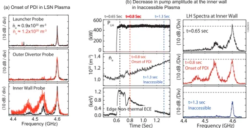
(a) Onset of PDI in LSN Plasma
(b) Decrease in pump amplitude at the inner wall in Inaccessible Plasma
LH Spectra at Inner Wall
FIGURE 4. (a) Onset of PDI at the HFS in a LSN plasma. Launched peak n∥= 1.9. (b) The inner wall probe measures the decrease in peak pump power when plasma becomes inaccessible in a LSN plasma. Launched peak n∥= 1.6.
EXPERIMENTAL RESULTS AND PDI ANALYSIS
PDI occurring at the HFS (HFS PDI) is observed to be spatially localized away from the LH launcher. Figure 4(a) compares the LH spectra before and after the onset of HFS PDI at three different locations in a LSN plasma. As
mentioned earlier, the onset density is about ne= 1.0× 10²⁰m−3. The inner wall probe measurements show that
the strength of pump power decreases with the growth of the sidebands, implying that pump power is lost and
redistributed to the sideband LH waves that are likely to have higher n∥. These sidebands are likely Landau-damped.
This interpretation is supported by the observation that only the inner wall probe detects a significant fraction of the sideband power. Furthermore, the peak pump power measured with the two probes at the LFS maintains its strength, implying that HFS PDI is a local effect. Note that pump broadening is observed as well when HFS PDI is intensified. When LH waves become inaccessible to plasma, inner wall probes detect little power reaching the HFS edge. For example, Figure 4(b) shows a decrease in peak pump power with the onset of HFS PDI, followed by a further reduction in peak pump power by about 15 dB in an inaccessible plasma. Note that, in this particular case, the launched peak
n∥ is 1.6 and the LH waves become inaccessible when ne& 1.2 × 10²⁰m−3. The reduction of peak pump power in
inaccessible plasma evidences that LH waves propagate in a multi-pass regime and that pump power cannot reach the HFS edge if there is a mechanism that prohibits the propagation of LH waves to the HFS. Thus, if PDI happens in front of the launcher on the first pass toward the HFS and is significant, it is expected that the reduction of pump power would be observed with the inner wall probes.
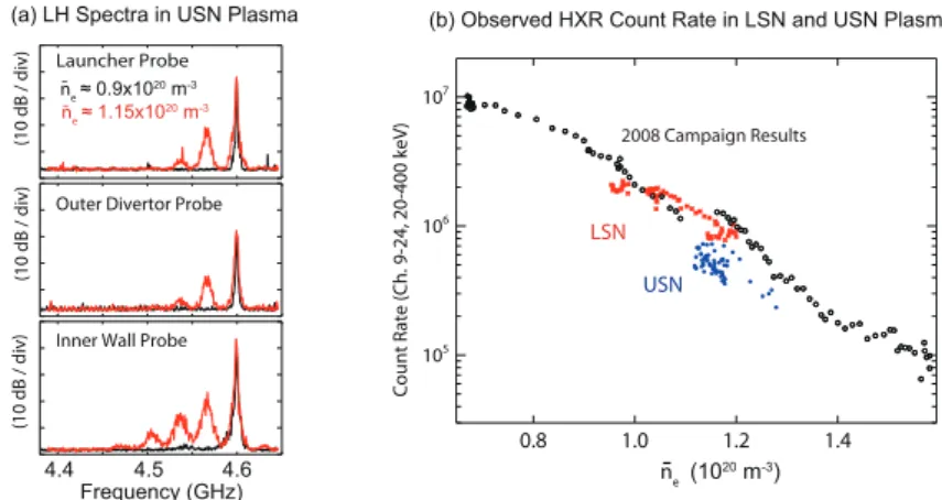
Figure 5 shows the LH spectra in USN plasmas below and above ne≈ 1.0×10²⁰m−3. In this case, the PDI threshold
density is found to be similar to that of HFS PDI in LSN plasmas. However, based on the frequency spacing between the harmonics, we infer that PDI is excited at the LFS edge (LFS PDI). Moreover, the sideband power is not as strong as that of HFS PDI. These characteristics of PDI are consistent with previous observations in other tokamaks [14, 8] in the following two ways: first, the observed spectra are similar in their shape regardless of the location of the probes. Our measurements revealed that even the inner wall probe detects the PDI excited at the LFS, suggesting that these
sidebands may have similar n∥to that of the pump in order to propagate from the LFS edge to the HFS edge without
being Landau-damped. Second, the observed sideband power remains weak unless the plasma density is further raised
such that f0/ flh(0)→ 2, where f0is the source frequency and flh(0) is the lower hybrid frequency at the plasma center.
This limit corresponds to the conventional ion cyclotron PDI limit [14]. In this limit, the parametric decay region is estimated to be localized at the plasma periphery near the launcher [8].
However, nearly unchanged pump strength at the inner wall below and above threshold density in our case (a current
drive regime where f0/ flh(0)≈ 3 ∼ 4) implies that a significant amount of pump power is not lost due to LFS PDI at
least on the first pass to the HFS. Our observations so far have not indicated any clear evidence that LFS PDI in front of the launcher causes a significant amount of pump depletion.
(10 dB / div) (10 dB / div) (10 d B / di v) Launcher Probe
Outer Divertor Probe
Inner Wall Probe ne ≈ 0.9x10²⁰ m-3 ne ≈ 1.15x10 20 m-3 -0.8 1.0 1.2 1.4 105 106 107 Cou nt Rate (C h. 9 -24, 20-400
keV) 2008 Campaign Results
4.4 4.5 4.6 Frequency (GHz)
n-e (1020 m-3) LSN
USN
(a) LH Spectra in USN Plasma (b) Observed HXR Count Rate in LSN and USN Plasma
FIGURE 5. (a) Onset of PDI at the LFS in USN plasmas. Launched peak n∥= 1.9. Note the inner wall probe also detects the PDI excited at the LFS. (b) Non-thermal Hard X-ray counte rate in LSN and USN plasmas as a function of ne. Overplotted are the
results from 2008 campaign.
between USN and LSN plasmas, although the two plasmas have shown different PDI behavior. Figure 5(b) shows that both USN and LSN plasmas resulted in a level of hard X-ray count rate consistent with the results obtained from the 2008 campaign. Given that we have observed an indication of pump depletion in LSN plasmas, the existing probes may not have been sensitive to a region where strong LFS PDI may occur. For example, the probe on the launcher may not be ideal to detect propagating sideband LH waves because it is likely that they propagate away from the launcher. Therefore, as discussed more in the final section, the role of LFS PDI needs further investigation with more extensive probe coverage.
In an attempt to explain the observed density threshold, we have calculated the homogeneous growth rate (γ) based
on the following parametric dispersion [14, 15]
ε+1 4χe(1 +χi) [ (µ−)2 ε− + (µ+)2 ε+ ] = 0, (1)
whereεis the dielectric constant of low frequency ion mode,ε±dielectric constant of upper(+) and lower(-) sideband
LH mode,χi(e)is the ion (electron) susceptibility of ion mode. Here,µ±is a coupling coefficient with the following
definition: µ±≈ e me k k± ( (k±∥)2E0∥2 ω4 0 +E 2 0⊥(k±⊥)2sin2θ ω2 0ωce2 )1/2 , (2)
where k is the wavenumber of ion mode, k± is the wavenumber of the upper and lower sideband, and E0∥(⊥)is the
strength of parallel (perpendicular) pump electric field. The first term inside the bracket is due to the parallel motion
of electrons and can be important at the plasma edge. The second term is due to the ⃗E× ⃗B motion of electrons and
is typically dominant the term as density increases due to the WKB enhancement of E0⊥.θis the angle between k⊥
and k±⊥, which can determine the strength of perpendicular coupling and the angle between the group velocities of
the pump and the sideband. The local electric field is found from the WKB approach. The upper sideband can be neglected because it is often found to be off-resonant, consistent with the observed LH spectra which exhibit relatively weaker upper sidebands as compared to the lower sidebands. The relevant ion modes are ion sound and ion cyclotron quasi-modes [16].
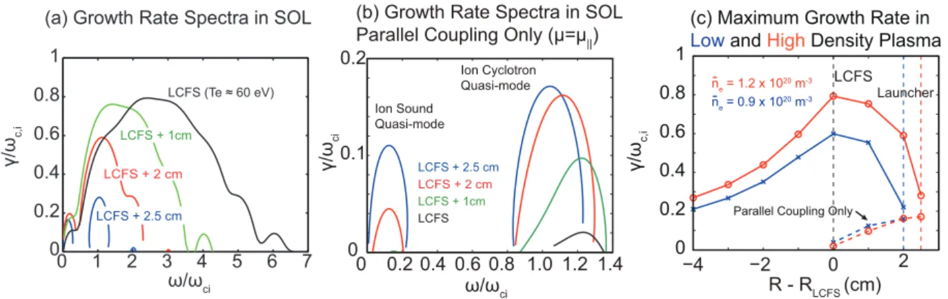
Regardless of the coupling types, ion cyclotron parametric decay is found to be dominant over ion sound parametric decay in C-Mod edge plasmas due to relatively higher edge density as compared to other tokamaks such as FTU [9] and
JET [17]. Figure 6(a) shows the homogeneous growth rate (γ) as a function of the normalized real frequency of the ion
mode (ω/ωci) at the LFS based on measured density and temperature profiles of high density USN plasmas (Figure 5
(a)) whenθ= 90◦. Our focus is given to the SOL region because the relatively higher temperature inside the separatrix
(Te& 60 ∼ 70eV) results in the shift of the real frequency corresponding to the maximumγ to higher ion cyclotron
harmonics. Thus, we expect that the observed PDI is excited at the plasma periphery as the observed dominant peak is
0 1 2 3 4 5 6 7 0 0.2 0.4 0.6 0.8 1 γ/ ωc, i ω/ωci LCFS (Te ≈ 60 eV) LCFS + 1cm LCFS + 2 cm LCFS + 2.5 cm
(a) Growth Rate Spectra in SOL
0 0.2 1.0 ω/ωci 0.4 0.6 0.8 1.2 1.4 0 0.1 0.2 γ/ ωci LCFS + 2 cm LCFS + 1cm LCFS Ion Sound Quasi-mode Ion Cyclotron Quasi-mode LCFS + 2.5 cm
(b) Growth Rate Spectra in SOL
Parallel Coupling Only (μ=μ||)
0 0.2 0.4 0.6 0.8 1 γ/ ωc, i −4 −2 0 2 R - RLCFS (cm) ne = 1.2 x 10 20 m-3 -ne = 0.9 x 10 20 m-3
-(c) Maximum Growth Rate in
Low and High Density Plasma
Parallel Coupling Only
LCFS
Launcher
FIGURE 6. (a) Homogeneous growth rate in the LFS SOL. (b) Homogeneous growth rate in the LFS SOL withµ∥only. (c) Maximum growth rate Vs. radial location in low and high density USN plasmas. k∥/cω0= 6 and k0∥/cω0= 2.
of ion cyclotron PDI. Figure 6(b) shows theγspectra when only the parallel coupling term is included. It shows that
even whenθ= 0◦, the ion cyclotron peak is dominant over the ion sound peak. Nonetheless, this calculation shows
that we cannot neglect the role of the ion sound PDI at the far SOL because, in a multi-pass regime, LH waves can be reflected at the cut-off layer or at the wall several times before being completely Landau-damped.
At the plasma edge near the launcher, the growth due to parallel coupling (and perpendicular coupling with small
θ) can be more important than the growth due to perpendicular coupling [8, 9]. The former can result in higher
convective growth due to more aligned group velocities of pump and sideband, resulting in longer residence time∆t of
the LH sideband within the pump and stronger amplification factor A≡γ∆t in determining the strength of the sideband
power. Note that the relatively lower frequency of the sideband LH mode than that of the pump will eventually make
the sideband convect out from the pump. On the other hand, in the perpendicular coupling case (θ= 90◦), two group
velocities are in a perpendicular direction, so the sideband is expected to quickly convect out of the pump region near
the LH launcher where a well-defined pump resonance cone is expected. The optimized angleθ in maximizing the
convective growth along the pump due to perpendicular case is found to be whenθ≈ 10◦∼ 20◦asγincreases and∆t
decreases with increasingθ. In this range,γdue to perpendicular coupling is on the order ofγdue to parallel coupling,
or weaker.
Another key finding is that the low density USN plasmas (ne≈ 0.9×10²⁰m−3) are even unstable to PDI. Figure 6(c)
compares the maximumγ as a function of the radial location for low and high density plasmas. Both plasmas have
a comparable growth rate, suggesting that convective growth is more important in determining the onset threshold. Therefore, an underlying cause of the observed onset of LFS PDI could be due to a weak radial penetration of the
pump in higher density plasmas (vg⊥/vg∥≈ω/ωpe). Then the pump can spend a longer period of time in the edge
where PDI is unstable, resulting in a higher convective growth.
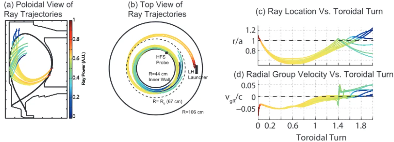
Given that edge plasma conditions are unstable to PDI, we have examined the pump ray trajectories near the inner wall to look for two possible convective growth mechanisms that may lead to the observed intense HFS PDI. First is the spatial broadening of pump LH waves. Figure 7(a) shows an example of the LH ray trajectories launched at the LFS plasma edge. The GENRAY [18] ray-tracing code with edge collisional model is used. The density and temperature profile outside the separatrix is based on a model with an exponentially decaying function. The rays are terminated after about two toroidal turns. The rays reach the HFS edge without being Landau-damped. This is also clearly seen in Figure 7(c), where the LH rays propagate toward the inner plasma edge instead of constantly radially penetrating toward the plasma core. Near the inner wall, the rays start to noticeably spread in the poloidal space after the reflection at the inner wall. While this spatial broadening of the rays can reduce pump power density, it can also reduce convective losses due to perpendicular coupling, unlike the case wherein there is a well-defined resonance cone near the LH launcher.
Second, a reduced radial group velocity may also enhance the convective growth. Figure 7(b) shows that the rays stay near the inner part of the plasma after about a half-toroidal turn. This is because the radial pump group velocity
stays near zero, as shown in Figure 7(d). In the parallel coupling limit (θ→ 0), ∆t can be defined as ∆t ≡ △/vgξ,
where△ is the (radial) distance across the pump region and vgξ is the group velocity of the sideband LH mode in that
0 0.2 0.4 0.6 0.8 1 R a y Po w e r (A. U .) 0 0.2 0.4 0.6 0.8 1 R a y Po w e r (A. U .) 0 0.2 0.4 0.6 0.8 1 R a y Po w e r (A. U .) 0 0.2 0.4 0.6 0.8 1 R a y Po w e r (A. U .) R=106 cm R= R0 (67 cm) R=44 cm Inner Wall LH Launcher HFS Probe 0.8 1 1.2 0 0.2 0.6 1 1.4 1.8 −0.05 0 0.05 Toroidal Turn r/a vgR/c (b) Top View of Ray Trajectories (a) Poloidal View of
Ray Trajectories (c) Ray Location Vs. Toroidal Turn
(d) Radial Group Velocity Vs. Toroidal Turn
FIGURE 7. (a) Poloidal projection of the LH ray trajectories. (b) Top view of the LH ray trajectories. (c) LH ray locations as a function of toroidal location. (d) Radial group velocity as as a function of toroidal location.
(a) Isometric View
of the off-midplane launcher
(b) Simulated LH Driven Current Density Profile
FIGURE 8. (a) Isometric view of the off-midplane launcher, which will be used together with the existing launcher (b) Simulated LH driven current density profile with (red) and without (black) the reversed lobe in the launched LH wavenumber spectum using the two launchers.
the excited sideband mode propagates along the pump. Slow vgξ can increase∆t, resulting in a higher amplification
factor. One can construct a similar case in the perpendicular coupling limit because one of the perpendicular directions to the pump group velocity can be the radial direction.
Therefore, both parallel and perpendicular coupling is expected to contribute to the growth of the sideband near the inner plasma edge where the resonance cone is broadened and radial group velocity slows down. The latter mechanism is somewhat analogous to the case of the conventional PDI limit [14] where both the parallel and perpendicular group
velocities of the sideband and the pump slow down significantly in the limit f0/ flh(0)→ 2, maximizing the convective
growth, although perpendicular coupling was identified as the dominant mechanism in the plasma core.
ENHANCING SINGLE PASS ABSORPTION WITH AN ADDITIONAL
OFF-MIDPLANE LAUNCHER
The observed PDI at the HFS edge can be suppressed by enhancing single pass absorption of LH waves, which will eliminate the presence of the pump near the HFS edge. Figure 8(a) is a schematic of the new off-mid-plane launcher that is being developed in Alcator C-Mod to improve single pass absorption, in conjunction with the existing launcher. The total net power will be 2 MW. Simulations show that two launchers can optimize the phase velocity interactions
between the LH waves from each launcher and achieve relatively high single pass absorption (∼ 80%) in moderately
hot temperature (Te0≈ 5keV), high density (ne0≈ 1.5 × 10²⁰m−3) I-mode plasmas [19]. In this case, as shown in
Figure 8(b), LH waves will be mostly damped at r/a≈ 0.65 and drive off-axis current. As most of the LH waves are
mechanisms such as collisional loss and full wave effects, all of which are particularly exacerbated when LH waves propagate near inner plasma edge.
Enhancing single pass absorption will also elucidate the role of the observed LFS PDI and its excitation location. Based on our available data, PDI is observed to be associated with the fall off in LHCD efficiency in high density plasmas. However, the effects of the observed LFS PDI are not still clear, owing to its apparently weak sideband power. While it is natural to expect that LFS PDI mostly occurs in front of the launcher, where LH power density is the highest, probe measurements indicate that the observed LFS PDI does not appear to cause significant pump depletion on the first pass toward the HFS edge. Thus, in order to explain a similar level in the non-thermal hard X-ray with a different level of PDI strength between USN and LSN plasmas, we cannot rule out the possibility that LFS PDI occurs at the LFS edge toroidally and poloidally away from the launcher in a multi-pass regime. For example, the LH ray shown in Figure 3(b) propagates toward the LFS edge where it is being reflected, possibly leading to the stronger convective
growth. On the other hand, it was reported [9] that about 20∼ 30% power can be inherently lost owing to PDI in
front of the launcher. Nonetheless, examining our observed LH spectra measured with the launcher probe obtained in
high density plasmas (ne≈ 1.4 × 10²⁰m−3) shows that the sideband power including the pump broadening and ion
cyclotron sidebands is about 10% of the pump power (4600±2MHz). Thus, more work is needed to characterize LFS
PDI to bridge the gap between the modeling and experimental results. In this view, enhancing single pass absorption will help isolate the loss mechanisms happening in front of the launcher from other loss mechanisms away from the launcher and allow us to identify and mitigate possible loss mechanisms. It will also help to recover expected current drive efficiency in ITER relevant high density plasmas by minimizing the parasitic edge effects.
ACKNOWLEDGMENTS
The authors gratefully acknowledge the support of the Alcator C-Mod team. This work is supported by US DOE Award Nos. DE-FC02-99ER54512 and DE-AC02-76CH03073.
REFERENCES
1. I. Hutchinson, R. Boivin, F. Bombarda, P. Bonoli, S. Fairfax, C. Fiore, J. Goetz, S. Golovato, R. Granetz, M. Greenwald, S. Horne, A. Hubbard, J. Irby, B. LaBombard, B. Lipschultz, E. Marmar, G. McCracken, M. Porkolab, J. Rice, J. Snipes, Y. Takase, J. Terry, S. Wolfe, C. Christensen, D. Garnier, M. Graf, T. Hsu, T. Luke, M. May, A. Niemczewski, G. Tinios, J. Schachter, and J. Urbahn, Physics of Plasmas 1, 1511 (1994).
2. P. Bonoli, R. Parker, M. Porkolab, J. Ramos, S. Wukitch, Y. Takase, S. Bernabei, J. Hosea, G. Schilling, and J. Wilson, Nuclear Fusion 40, 1251 (2000).
3. G. Wallace, R. Parker, P. Bonoli, A. Hubbard, J. Hughes, B. LaBombard, O. Meneghini, A. Schmidt, S. Shiraiwa, D. Whyte, et al., Physics of Plasmas 17, 082508 (2010).
4. G. M. Wallace, I. Faust, O. Meneghini, R. Parker, S. Shiraiwa, S. Baek, P. Bonoli, A. Hubbard, J. Hughes, B. LaBombard, et al., Physics of Plasmas 19, 062505 (2012).
5. P. Bonoli, J. Ko, R. Parker, A. Schmidt, G. Wallace, J. Wright, C. Fiore, A. Hubbard, J. Irby, E. Marmar, et al., Physics of Plasmas 15, 056117–056117 (2008).
6. M. Porkolab, S. Bernabei, W. Hooke, R. Motley, and T. Nagashima, Physical Review Letters 38, 230–233 (1977). 7. Y. Takase, and M. Porkolab, Physics of Fluids 26, 2992–3003 (1983).
8. Y. Takase, M. Porkolab, J. Schuss, R. Watterson, C. Fiore, R. Slusher, and C. Surko, Physics of Fluids 28, 983 (1985). 9. R. Cesario, A. Cardinali, C. Castaldo, F. Paoletti, W. Fundamenski, S. Hacquin, et al., Nuclear fusion 46, 462 (2006). 10. S. Baek, R. Parker, S. Shiraiwa, G. Wallace, P. Bonoli, D. Brunner, I. Faust, A. Hubbard, B. LaBombard, and M. Porkolab,
Plasma Physics and Controlled Fusion 55, 052001 (2013).
11. S. Shiraiwa, O. Meneghini, R. Parker, G. Wallace, J. Wilson, I. Faust, C. Lau, R. Mumgaard, S. Scott, S. Wukitch, et al., Nuclear Fusion 51, 103024 (2011).
12. G. Wallace, et al. (2013), Nuclear Fusion to appear.
13. N. Smick, and B. LaBombard, Review of Scientific Instruments 80, 023502–023502 (2009). 14. M. Porkolab, Physics of Fluids 20, 2058 (1977).
15. C. Liu, V. Tripathi, V. Chan, and V. Stefan, Physics of Fluids 27, 1709 (1984). 16. M. Porkolab, Physics of Fluids 17, 1432 (1974).
17. R. Cesario, L. Amicucci, C. Castaldo, M. Kempenaars, S. Jachmich, J. Mailloux, O. Tudisco, A. Galli, A. Krivska, et al., Plasma Physics and Controlled Fusion 53, 085011 (2011).
18. A. Smirnov, and R. Harvey, Bulletin of the American Physical Society 40 (1995). 19. S. Shiraiwa, et al. (2013), submitted to Nuclear Fusion.