Publisher’s version / Version de l'éditeur:
ACM Computing Surveys, 35, 1, 2003
READ THESE TERMS AND CONDITIONS CAREFULLY BEFORE USING THIS WEBSITE. https://nrc-publications.canada.ca/eng/copyright
Vous avez des questions? Nous pouvons vous aider. Pour communiquer directement avec un auteur, consultez la première page de la revue dans laquelle son article a été publié afin de trouver ses coordonnées. Si vous n’arrivez pas à les repérer, communiquez avec nous à [email protected].
Questions? Contact the NRC Publications Archive team at
[email protected]. If you wish to email the authors directly, please see the first page of the publication for their contact information.
Archives des publications du CNRC
This publication could be one of several versions: author’s original, accepted manuscript or the publisher’s version. / La version de cette publication peut être l’une des suivantes : la version prépublication de l’auteur, la version acceptée du manuscrit ou la version de l’éditeur.
Access and use of this website and the material on it are subject to the Terms and Conditions set forth at
View Planning for Automated 3D Object Reconstruction Inspection
Scott, William; Roth, Gerhard; Rivest, J.F.
https://publications-cnrc.canada.ca/fra/droits
L’accès à ce site Web et l’utilisation de son contenu sont assujettis aux conditions présentées dans le site LISEZ CES CONDITIONS ATTENTIVEMENT AVANT D’UTILISER CE SITE WEB.
NRC Publications Record / Notice d'Archives des publications de CNRC:
https://nrc-publications.canada.ca/eng/view/object/?id=c9a6149f-27d0-4269-8122-80dd6104c0a1 https://publications-cnrc.canada.ca/fra/voir/objet/?id=c9a6149f-27d0-4269-8122-80dd6104c0a1Council Canada Institute for Information Technology de recherches Canada Institut de technologie de l'information
View Planning for Automated 3D Object
Reconstruction and Inspection *
Scott, W., Roth, G., and Rivest, J.F.
March 2003
* published in The ACM Computing Surveys, 35(1): 64-96. March 2003. NRC 45866.
Copyright 2003 by
National Research Council of Canada
Permission is granted to quote short excerpts and to reproduce figures and tables from this report, provided that the source of such material is fully acknowledged.
Reconstruction and Inspection
WILLIAM R. SCOTT and GERHARD ROTH
National Research Council of Canada
AND
JEAN-FRANC¸ OIS RIVEST
University of Ottawa
Laser scanning range sensors are widely used for high-precision, high-density three-dimensional (3D) reconstruction and inspection of the surface of physical objects. The process typically involves planning a set of views, physically altering the relative object-sensor pose, taking scans, registering the acquired geometric data in a common coordinate frame of reference, and finally integrating range images into a
nonredundant model. Efficiencies could be achieved by automating or semiautomating this process. While challenges remain, there are adequate solutions to semiautomate the scan-register-integrate tasks. On the other hand, view planning remains an open problem—that is, the task of finding a suitably small set of sensor poses and
configurations for specified reconstruction or inspection goals. This paper surveys and compares view planning techniques for automated 3D object reconstruction and inspection by means of active, triangulation-based range sensors.
Categories and Subject Descriptors: I.2.9 [Artificial Intelligence]: Robotics—sensors; I.2.10 [Artificial Intelligence]: Vision and Scene Understanding—Modeling and
recovery of physical attributes; I.4.1 [Image Processing and Computer Vision]: Digitization and Image Capture—Scanning; I.5.4 [Pattern Recognition]: Applications—Computer vision
General Terms: Algorithms, Design, Measurement, Performance
Additional Key Words and Phrases: View planning, range images, object reconstruction, object inspection
1. INTRODUCTION
The demand for high—quality three di-mensional (3D) virtual models of complex physical objects is growing in a wide range
This work was partially sponsored by scholarships from the National Science and Engineering Research Council (Canada), the Ontario Graduate Student Scholarship program, and the University of Ottawa grad-uate scholarship program. The research was conducted while the principal author was a guest researcher at the National Research Council of Canada’s Institute for Information Technology.
Authors’ addresses: W. R. Scott and G. Roth, Computational Video Group, Institute for Information Tech-nology, National Research Council, M-50, 1200 Montreal Rd., Ottawa, Ont., Canada, K1A 0R6; email: {william.scott, [email protected]}; J.-F. Rivest, Defence Research Establishment Ottawa, 3701 Carling Ave., Ottawa, Ont., Canada, K1A 0Z4.
Permission to make digital/hard copy of part or all of this work for personal or classroom use is granted with-out fee provided that the copies are not made or distributed for profit or commercial advantage, the copyright notice, the title of the publication, and its date appear, and notice is given that copying is by permission of ACM, Inc. To copy otherwise, to republish, to post on servers, or to redistribute to lists requires prior specific permission and/or a fee.
c
°2003 ACM 0360-0300/03/0300-0064 $5.00
of applications (e.g., industrial, training, medical, entertainment, cultural, archi-tectural). Computer graphics can pro-duce synthetic models for some of these
applications by a combination of artis-tic and technical design processes. In the computer vision field, on the other hand, model acquisition is achieved by measur-ing the shape and visual properties of real physical objects. Numerous applications require the computer vision approach to object surface reconstruction.
Automating or semiautomating the cur-rent manual, time-consuming reconstruc-tion process would improve productiv-ity and qualproductiv-ity, reduce operator skill level and rework requirements, and lower cost. While a limited number of commer-cial systems (Hymarc Ltd., Rapidscan, www.hymarc.com; Digibotics Ltd., Adap-tive Scan, www.digibotics.com) offer semi-automated tools to aid scanning, there is presently no general purpose com-mercial system for automated object reconstruction.
Both mechanical and optical geomet-ric measurement sensors are used for 3D object reconstruction and inspec-tion. Mechanical Coordinate Measur-ing Machines (CMMs) use precise me-chanical movement stages and touch probes to achieve very high measurement precision—around 1 µm for a suitably cal-ibrated high-end machine operated by a skilled technician. However, the acquisi-tion and operating costs for such precision are high. With a relatively low data ac-quisition rate, CMMs are generally suit-able for sparse sampling applications only. While their measurement precision is in-ferior to CMMs, optical sensors have lower capital and operating costs and are capa-ble of dense, noncontact sampling at high throughput rates.
This survey deals with view planning for automated high-quality object recon-struction or inspection by means of ac-tive, triangulation-based range cameras. In this context, view planning is the pro-cess of determining a suitable set of view-points and associated imaging parameters for a specified object reconstruction or in-spection task with a range camera and po-sitioning system. By object reconstruction we mean acquisition of a virtual computer model of the surface of a physical object. This is normally a triangulated
polygo-nal mesh representation of surface geom-etry. Alternative surface representations such as splines, swept cylinders, and su-per quadratics are advantageous in spe-cial cases but are neither as general pur-pose nor as flexible as a triangular mesh.
While dealing mainly with object recon-struction, the techniques examined here also apply to inspection. The later is an easier problem, having the advantage of a preexisting model. Essential information can be collected off-line in a suitable data structure, allowing different tasks to be planned quickly online.
Many applications are concerned with shape only. A growing number also seek coregistered surface geometry and surface visual texture or reflectance properties. Capturing high-quality surface geome-try (the focus of this survey) is a pre-requisite for the accurate measurement of reflectance properties which may be achieved simultaneously with some range sensors [Baribeau et al. 1991].
The paper is structured as follows. Af-ter an overview of the problem (Section 2), view planning requirements are defined in detail (Section 3). We then reference re-lated surveys in the field (Section 4) be-fore presenting a survey of view planning methods in two broad categories: model-based (Section 5) and non-model-model-based (Section 6). Finally, we compare (Section 7) and critique (Section 8) existing methods with respect to the defined requirements, examine related issues (Section 9), and conclude with a discussion of the remain-ing open problems (Section 10).
2. PROBLEM OVERVIEW 2.1. Imaging Environment
The imaging environment (Figure 1) for object reconstruction consists of a range camera, positioning system, various fix-tures, and the target object.
Range camera. The principal compo-nent of the imaging environment is a range camera—a sensor for 3D shape mea-surement. A wide variety of technologies are used for measuring object shape [Besl 1989]. Range cameras can be categorized
Fig. 1. Imaging environment.
into active and passive devices. The most common passive range-finding technol-ogy, stereo vision, can provide accurate measurement at short stand-off distances. However, passive stereo depends on vi-sual texture on the target object, is sub-ject to illumination constraints and in-terference, and can provide only sparse depth measurement. With an integral il-lumination source, active sensors are ca-pable of dense range measurement and are less susceptible to external interfer-ence. However, the illumination source (frequently a laser) may impose system safety constraints. Active range sensors can be divided into two subcategories, time-of-flight and triangulation. Time-of-flight systems require very accurate timing sources and typically provide modest resolution (generally centimeter but occasionally millimeter accuracy) for longer range applications, that is, tens to thousands of meters [Amann et al. 2001]. They are best suited to distance measurement and environment model-ing at medium to long ranges. Many different types of triangulation sensors have been developed and are in wide usage. All are based on the principle of triangulating a measurement spot on the object from a physically separate camera optical source and detector. By simple geometry, the x, z coordinates of the illuminated spot on the object are calculated (Figure 2). In general, active triangulation-based range cameras are ca-pable of very precise (≤100 µm), dense depth measurements (many samples per square millimeter) over relatively small
Fig. 2. Conventional active triangulation. (From El-Hakim and Beraldin[1994]; c°IEEE 1994.)
sensor frustums up to about a meter in standoff distance [El-Hakim and Beraldin 1994]. In the following, z is range, x is
dis-tance across the scan, f0is the sensor focal
length, p is the position of the imaged spot on the sensor detector, and θ is the laser scan angle:
z = d f0
p+ f0tan θ
, (1)
x = ztan θ. (2)
This survey focuses on triangulation-based active laser range scanners as they are widely used for precise measurement for both object reconstruction and in-spection. Several sensor attributes impact view planning. The optical baseline, the distance between the laser and the opti-cal receiver, is significant with respect to the measurement stand-off distance. Con-sequently, coverage shadow zones arise with respect to visibility by the laser, the optical receiver, or both. The sensor field of view, depth of field, and there-fore frustum volume are limited. Mea-surement precision and sampling density are highly nonuniform within the frus-tum. Additionally, measurement is subject to random nonisotropic geometric noise [Beraldin et al. 1993] and several artifact phenomena [Curless and Levoy 1996].
Positioning system. Imaging all sides of an object requires a variety of viewing per-spectives. Thus, a positioning system is
required to move the sensor, the object, or both in some combination. An impfect positioning system introduces pose er-ror, which has two consequences. First, a planned view is not the one actually ex-ecuted. Sufficiently severe pose error can render view planning futile. Second, the resulting pose uncertainty necessitates an image registration stage.
Viewpoint space. Viewpoints should be
treated as generalized viewpoints (v, λs)
consisting of sensor pose v and a set of
controllable sensor parameters λs
[Tara-banis et al. 1995b; Roberts and Marshall 1997; Pito 1997a]. Thus each viewpoint has an associated sensor configuration. Sensor pose is limited by the degrees of freedom and range of motion of the posi-tioning system. Viewpoint space V is the set of generalized viewpoints defined by the range and sampling of these param-eters.
Object. The object is the feature to be modeled. Specifically, we wish to cap-ture its 3D shape. Object surface space S is the set of 3D surface points sampled on the object. These can be considered as ver-tices in the resulting object mesh model.
Fixtures. The object must be supported by a fixture of some kind. Consequently, acquisition of all-aspect views will require the object to be repositioned on the fix-ture at least once and more likely sev-eral times. After each repositioning, the new relative pose must be determined to bring the system into a single coordinate frame. Fixtures, the positioning system, and any other structures in the imaging work space I introduce occlusion and col-lision avoidance considerations.
2.2. Reconstruction Cycle
The classical model building cycle
(Figure 3) consists of four main phases— plan, scan, register, and integrate. A sequence of views, the view plan or
next-best-view (NBV) list N, must be computed. The sensor must be moved to the appropriate pose and configured with appropriate settings, after which scans
Fig. 3. Object reconstruction cycle. are taken. Unless the positioning system is error-free, acquired range images must be registered by an image-based regis-tration technique such as the standard Iterative Closest Point (ICP) method [Besl and McKay 1992]. Subsequently, registered images must be combined into a single, nonredundant model—a process commonly known as integration. The process continues until some stopping criteria are satisfied.
These are the basic reconstruction steps. Other related activities are briefly as follows. Calibration of both sensor and positioning system is an essential prereq-uisite and may need to be repeated after certain positioning system reconfigura-tions. Filtering of noise and artifacts is re-quired at several stages. Depending on the application, there may also be a require-ment for model compression or decima-tion and for texture mapping of reflectance data onto the geometry [Baribeau et al. 1991].
While challenges remain, adequate so-lutions exist to automate the
scan-register-integrate functions.1 However,
automated view planning remains an open problem despite two decades of research. For large reconstruction tasks, the image registration and integration (model build-ing) functions can be very time consum-ing. By the time deficiencies in the partial model are discovered, the imaging team may have left the site or access to the ob-ject may no longer be readily available. Hence, there is a need for a view planning 1 Research on ICP refinements remains an active field of research. For example, see Rusinkiewicz and Levoy [2001] and Langis et al. [2001]. Research on model building also remains active, with a number of open issues [Roth 2000].
scheme capable of developing reliable view plans in a timely manner for comprehen-sive object coverage in accordance with all technical criteria of the reconstruction task.
A different approach is to automate only the register-integrate functions and rely on human-based view planning and scanning. Huber [2001] used graph-based methods to increase the reliability of multiview registration and integration. H´ebert [2001] used a hand-held scanner to sweep the object as one would use a paint sprayer. Both techniques employ progressive model building. Both require near real-time registration and integra-tion, difficult tasks whose computational complexity is sensitive to model size and number of images taken. Registration of single 1D scans faces reliability and sta-bility issues. Humans are relatively good at high-level view planning for coverage of simple objects but even experienced op-erators will encounter considerable diffi-culty with topologically and geometrically complex shapes. A visualization feedback loop can overcome some of these difficul-ties. Hand-held or even robotically sup-ported sensors will introduce pose error with consequences discussed later in this review. And, of course, heavy reliance on a human operator defeats the ultimate ob-jective of full automation. Notwithstand-ing these weaknesses, human-based view planning techniques are good candidates as interim semiautomated measures for applications with modest quality objec-tives. The balance of this review is re-stricted to machine-based view planning.
2.3. The View Planning Problem
From the foregoing, it is apparent that the view planning problem (VPP) involves reasoning about the state of knowledge of three spaces—object surface space S, viewpoint space V , and imaging work space I . While tied to 3D surface geometry,
Sis amenable to 2D parameterization. In
the unrestricted case, the pose component of viewpoint space V is six dimensional— three position and three rotation. Config-urable sensor parameters such as laser
power and scan length can further raise the dimensionality of generalized
view-point space, which we indicate as 6D+.
Imaging workspace I is the 3D region ca-pable of being viewed by the sensor over the full range of the positioning system. It is of concern primarily for visibility analy-sis and collision avoidance considerations. The complexity of the VPP is immediately apparent from the high dimensionality of the search spaces in S, V , and I .
Given this imaging environment and re-construction cycle, the view planning task is deceptively simple, yet computationally complex. Expressed informally, the view planning problem is as follows:
For a given imaging environment and target object, find a suitably short view plan N sat-isfying the specified reconstruction goals and achieve this within an acceptable computation time.
N will be a subset (preferably a very
small subset) of viewpoint space V , that is, N ⊂ V . As the View Planning Prob-lem has been shown to be NP-Complete ([Tarbox and Gottschlich 1995]; [Scott 2002]), in most realistic reconstruction or inspection tasks it is impractical to seek an absolute minimal length view plan. What is an “acceptably short” computa-tion time is applicacomputa-tion dependent. In an industrial setting, object reconstruc-tion involves repetitive modeling of dif-ferent objects. In this case, throughput is critical, emphasizing time-efficient al-gorithms. Perhaps some aspects of qual-ity, such as the view plan length, may be traded off in the interests of computational efficiency. In some reconstruction tasks, the primary objective is model quality and scanning efficiency is secondary. Inspec-tion applicaInspec-tions involving repetitive ex-ecution of an inspection plan on a produc-tion line place a premium on view plan ef-ficiency over the time taken to create it.
Several other machine vision applica-tions also involve view planning, such as environment modeling [Sequeira and Gonc¸alves 2002], autonomous exploration [Tremblay and Ferrie 2000], and sensor-based robot path planning [Yu and Gupta
techniques, and sensors appropriate for these applications are somewhat different than for high-quality object reconstruction/inspection. These applica-tions typically have much lower accuracy and sampling density requirements but potentially larger models, so different sensors may be appropriate such as time-of-flight (optical, sonar or radar) as well as passive optical technology.
2.4. Performance-Oriented Reconstruction
High-quality model building requires view planning for performance-oriented recon-struction [Scott et al. 2000], which is de-fined as model acquisition based on a set of explicit quality requirements expressed in a model specification. High-quality inspec-tion tasks are also generally specificainspec-tion- specification-driven. In addition to all-aspect coverage, measurement quality may be specified in terms of precision, sampling density, and perhaps other quality factors. Specified measurement quality may be fixed or vari-able over the object surface.
Performance-oriented view planning re-quires suitable models of both sensor and positioning system performance. These can be combined in an imaging environ-ment specification. Specifically, it requires the following:
—a sensor model with a description of the camera geometry and frustum geome-try and a characterization of measure-ment performance within the calibrated region; and
—a positioning system model describing the degrees of freedom, range of motion, and positioning performance within the movement envelope.
There has been relatively little work on performance-oriented view planning. Cowan and Kovesi [1988] used a con-straint satisfaction approach for sensor lo-cation subject to task requirements which included resolution, focus, field of view, visibility, view angle, and prohibited re-gions. The MVP system developed by Tarabanis et al. [1995] automatically syn-thesizes views for robotic vision tasks with intensity cameras based on a task
speci-fication as well as a geometric model of the scene and optical models of the sen-sor and illumination sources. The MVP task specification includes visibility, field of view, resolution, focus, and image con-trast. Soucy et al. [1998] described a sys-tem for automatically digitizing the sur-face of an object to a prescribed sampling density using a contour following scheme. Prieto et al. [1999, 2001] set CAD-based inspection criteria based on range sensor performance characterization. A number of authors have considered grazing angle as a subjective quality measure. Other-wise, the objective of most work in the field has been explicitly or implicitly limited to full surface coverage. Recently, Scott et al. [2000, 2001b] used a model-based, mul-tistage approach to performance-oriented view planning based on an input specifica-tion for sampling precision and density.
3. VIEW PLANNING REQUIREMENTS
In this section, we define requirements and performance measures for the view
planning process in greater detail.2 The
requirements are drawn up from a re-search perspective. Additional develop-ment and system integration details will arise when moving prototype view plan-ning algorithms to a production configura-tion of an automated object reconstrucconfigura-tion or inspection system.
3.1. Assumptions
To begin, our definition of the view planning problem for object reconstruc-tion and inspecreconstruc-tion is based on several assumptions:
—Both the range camera and positioning system are calibrated and calibration parameters are available to the view planning module.
—The imaging work space is compatible with object size and shape.
2Pito [1997a] also provided a good description of the view planning problem and defined constraints on the choice of the next-best-view and desirable prop-erties of view planning algorithms.
—Range camera performance is compati-ble with the model specification for the reconstruction task.
—The sensor and positioning system have compatible performance. Specifi-cally, pose error is compatible with the volume of the range camera frustum. —Object shape is compatible with sensor
capabilities.
—Object material properties are compati-ble with sensor capabilities.
The last two items merit elaboration. Range cameras are inherently sampling devices. Therefore, the reconstruction pro-cess is subject to the limitations of a sam-pled representation of continuous surface shape. The familiar sampling theorem for 1D and 2D signals does not extend to three dimensions. As there is no natural low-pass filter for 3D physical shape, alias-ing effects can be anticipated. Convoluted shapes can easily be conceived which can-not be fully imaged by a range camera, for example, a gourd or a sea urchin-like shape. Deep cavities, deep holes, or mul-tiple protrusions will be troublesome or completely impractical to image. There-fore, practicality requires that object ge-ometry and topology be “reasonable.”
Laser scanners have difficulty with cer-tain materials. They perform best with material having surface scattering proper-ties and a relatively uniform reflectance, neither overly absorbent nor overly re-flective. Natural or humanly made ma-terial with volume scattering properties such as hair and glass produce multi-ple reflections over a surface depth zone, degrading or prohibiting accurate range measurement.
The dynamic range of the current gen-eration of range sensors is limited. Exces-sively absorbent material scatters insuf-ficient light, causing “drop outs,” that is, missing data. Shiny surfaces are charac-terized by specular reflection. Depending on illumination and observation geome-try, specular surfaces may result in drop outs due to insufficient scattered energy or outliers or drop outs (depending on cam-era design) due to receiver saturation from
Table I. View Planning Requirements
Category Requirement
Model quality specification Generalizable algorithm Generalized viewpoints General View overlap
Robust Efficient Self-terminating
Minimal a priori knowledge Object Shape constraints
Material constraints Frustum
Sensor Shadow effect
Measurement performance 6D pose Positioning Pose constraints System Positioning performance
excessive received energy. Multiple reflec-tions on a shiny surface in corner regions can also produce wild measurements. Fi-nally, abrupt reflectance changes will pro-duce edge effects in the form of measure-ment biases and artifacts [Curless and Levoy 1996].
Consequently, the current state-of-the-art is limited to view planning for ob-jects with “reasonable” shapes and benign reflectance characteristics. Some view planning techniques are applicable to re-stricted shape classes, such as manufac-tured objects constructed of a limited set of shape primitives. The issue of extend-ing view plannextend-ing to objects with more difficult reflectance characteristics is ad-dressed in Section 10.1.
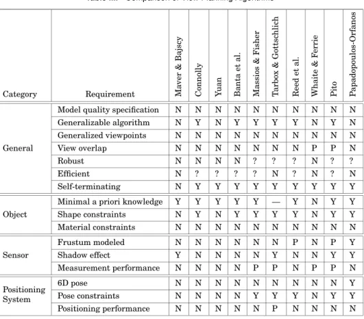
3.2. Constraints and Requirements
The following constraints and require-ments apply to the view planning task for object reconstruction. They are sum-marized in Table I under the categories of general, object, sensor, or positioning sys-tem. The following amounts to a “research specification” for a view planning system. Where objectives are quantified, it is pre-sumed that research-quality algorithms
are subject to refinement, development, and system integration on suitable pro-duction hardware and software platforms.
3.2.1. Model Quality Specification. By def-inition, performance-oriented view plan-ning is based on a model specification con-taining explicit, quantified, model quality requirements such as measurement pcision and sampling density. For object re-construction, there is usually an implicit requirement for 100% surface coverage. In other applications such as inspection, it may be appropriate to limit coverage to specified object regions.
3.2.2. Generalizable Algorithm. For wide applicability, the technique should apply to a broad class of range sensors, position-ing systems, and objects.
3.2.3. Generalized Viewpoints. In addition to sensor pose, the view planning algo-rithm should plan reconfigurable sensor parameters such as laser power and scan length through the use of generalized viewpoints.
3.2.4. View Overlap. The algorithm should provide the degree of image overlap necessary for integration and registration. Integration requires image overlap along the boundaries of adjacent images in the view plan. If pose error is such that image-based registration is required, the image set should have sufficient shape complexity in overlapping regions for registration of the image set within the specified precision.
3.2.5. Robust. The view planning algo-rithm should be immune to catastrophic failure, handle sensor and positioning sys-tem noise and artifacts, and require mini-mal operator intervention.
3.2.6. Efficient. The view planning al-gorithm should be sufficiently efficient to be competitive with skilled human operators. As an initial goal, the algo-rithm should be capable, with production-quality hardware and software, of
produc-ing a specification-compliant view plan for a moderately complex object within 1 h.
3.2.7. Self-Terminating. The view plan-ning algorithm should recognize when the goal has been achieved or when progress toward it has stalled.
3.2.8. Limited a priori Knowledge. The view planning algorithm should be effec-tive with minimal a priori object knowl-edge, specifically no more than approxi-mate bounding dimensions and centroid.
3.2.9. Shape Constraints. The view plan-ning algorithm should be effective with all reasonable object geometry and topology that is compatible with sensor measure-ment capabilities.
3.2.10. Material Constraints. The algo-rithm should be effective with all object
material properties compatible with
sensor measurement capabilities.
3.2.11. Frustum. Sensor frustum shape should be modeled. This includes sensor depth of field, field of view, and scan length or scan arc.
3.2.12. Shadow Effect. The bistatic na-ture of the sensor should be modeled—that is, the physical separation of the laser and detector.
3.2.13. Measurement Performance. Sen-sor measurement performance should be modeled, including variation of mea-surement precision and sampling density within the frustum and surface inclina-tion effects. The following range camera artifacts should be modeled: geometric and reflectance step edges and multiple reflections.
3.2.14. 6D Pose. The view planning al-gorithm should handle a positioning sys-tem with an unconstrained pose space-three position and space-three rotation.
3.2.15. Pose Constraints. The view plan-ning algorithm should model constraints
on the degrees of freedom and range of mo-tion of the posimo-tioning system.
3.2.16. Positioning System Performance.
Positioning system performance should be modeled to include pose error and repositioning/reconfiguration time.
3.3. Performance Measures
To date, adequate standards for quantify-ing view plannquantify-ing performance have not existed. This complicates the comparative assessment of view planning algorithms. We propose the following measures for evaluating view planning algorithm per-formance for a given reconstruction task with a given imaging environment: —View plan quality The quality of a view
plan is determined by the quality of the reconstruction it generates. This can be expressed as the overall verified
measurability3m
vof the reconstruction
with respect to the model specification.
mvis an indicator of the fidelity and
ro-bustness of the view planning process plus the adequacy of the discretization schemes for viewpoint space and surface
space. The goal is mv=1.0.
—View plan efficiency A measure of view plan efficiency is the length of the gen-erated view plan relative to the opti-mum achievable for that task, that is,
ev= nO pt/n, where n = |N |. As it may be
impractical to determine with certainty
the optimum view plan length nO pt for
complex reconstruction tasks, a suitable surrogate is the length of the best
solu-tion nBestfound thus far among all view
planning techniques examined for the
same task, that is, nO pt ≈ nBest. ev is
an indicator of the efficiency and com-pleteness of discretization schemes for viewpoint and surface space and the ef-ficiency of the set covering process. The
goal is ev=1.0.
3Verified measurability of a reconstruction can be seen as the ratio of reconstructed surface area com-pliant with the specified model criteria to the overall object surface area. For more precise definitions, re-fer to Scott et al. [2001b, 2002].
—View plan computational efficiency Mea-sures of the computational cost of gen-erating the view plan are computa-tional complexity and execution time on a defined platform. While each has weaknesses, together they provide a reasonable appreciation of algorithm performance. Computational efficiency indicates the efficiency of discretiza-tion schemes for viewpoint and surface space, visibility analysis, and the set covering process. Computational effi-ciency goals are application-dependent.
4. RELATED SURVEYS
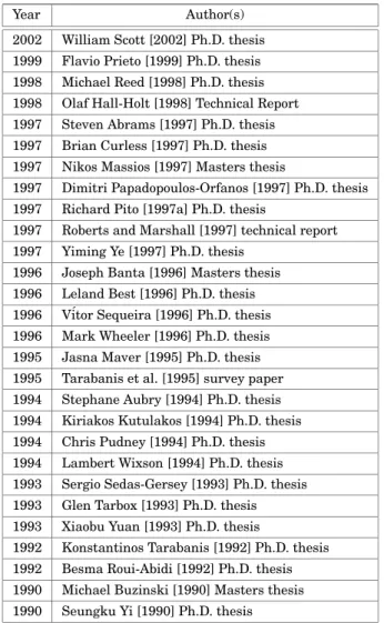
Surveys relevant to view planning for ob-ject reconstruction can be found primarily in doctorate and masters theses published over the last decade (Table II).
In a brief and clearly written tech-nical report addressing only seven pa-pers (Banta et al. [1995], Connolly [1985], Hutchinson and Kak [1989], Maver and Bajcsy [1993], Pito [1996b], Tarabanis et al. [1995a], and Whaite and Ferrie [1990]), Hall-Holt [1998] quickly zeroed in on two key issues—representation of available geometric information and how to deal with the potentially vast search space. While he did not answer the ques-tions he posed, Hall-Holt succinctly exam-ined from several perspectives the view planning approaches taken by some of the most notable authors. The survey con-cluded with a discussion of open issues: algorithm efficiency in the presence of large amounts of data, appropriate geo-metrical representations, hybrid models, multiresolution techniques, ray tracing avoidance, quantitative performance as-sessment, performance benchmarks, and improved scanner models.
The classic survey by Tarabanis
et al. [1995a], considered three vision
tasks—inspection, recognition, and
reconstruction—but focused almost exclu-sively on the first of these. The underlying perspective was that of conventional intensity imaging, although a few refer-ences were made to range imaging. View planning was categorized as following one of three paradigms—synthesis, generate
Table II. View Planning Surveys
Year Author(s)
2002 William Scott [2002] Ph.D. thesis 1999 Flavio Prieto [1999] Ph.D. thesis 1998 Michael Reed [1998] Ph.D. thesis 1998 Olaf Hall-Holt [1998] Technical Report 1997 Steven Abrams [1997] Ph.D. thesis 1997 Brian Curless [1997] Ph.D. thesis 1997 Nikos Massios [1997] Masters thesis
1997 Dimitri Papadopoulos-Orfanos [1997] Ph.D. thesis 1997 Richard Pito [1997a] Ph.D. thesis
1997 Roberts and Marshall [1997] technical report 1997 Yiming Ye [1997] Ph.D. thesis
1996 Joseph Banta [1996] Masters thesis 1996 Leland Best [1996] Ph.D. thesis 1996 V´itor Sequeira [1996] Ph.D. thesis 1996 Mark Wheeler [1996] Ph.D. thesis 1995 Jasna Maver [1995] Ph.D. thesis 1995 Tarabanis et al. [1995] survey paper 1994 Stephane Aubry [1994] Ph.D. thesis 1994 Kiriakos Kutulakos [1994] Ph.D. thesis 1994 Chris Pudney [1994] Ph.D. thesis 1994 Lambert Wixson [1994] Ph.D. thesis 1993 Sergio Sedas-Gersey [1993] Ph.D. thesis 1993 Glen Tarbox [1993] Ph.D. thesis 1993 Xiaobu Yuan [1993] Ph.D. thesis
1992 Konstantinos Tarabanis [1992] Ph.D. thesis 1992 Besma Roui-Abidi [1992] Ph.D. thesis 1990 Michael Buzinski [1990] Masters thesis 1990 Seungku Yi [1990] Ph.D. thesis
and test, or expert system. The open problems in view planning circa 1995 as seen by Tarabanis et al. [1995a] were the following:
—modeling and incorporating other con-straints such as integrating collision avoidance with view planning, dynamic sensor planning, and modeling the oper-ating range of the employed sensor; —modeling and incorporating other
sen-sors such as tactile, range, force-torque, and acoustic sensors;
—relaxing some of the assumptions made in current approaches such as feature uncertainty and error characterization;
—illumination planning to include higher-order lighting and reflectance models, multiple sources, specularity, and inter-reflections; and
—sensor and illumination modeling to in-clude mapping model parameters to con-trollable sensor settings and accurate sensor noise models.
A comprehensive survey of automated visual inspection systems by Newman and Jain [1995] considered binary, intensity, colored and range image sensors for a wide range of inspection applications.
These surveys categorized view plan-ning methods in several different ways.
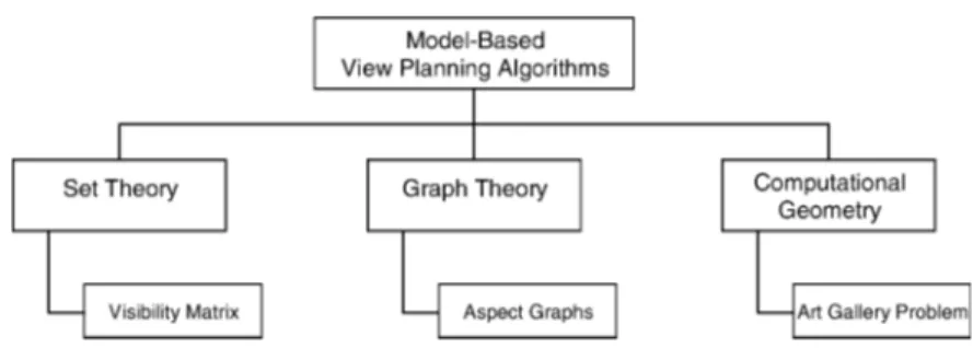
Fig. 4. Model-based view planning algorithms. From our perspective, we begin with two
top level categories—model-based or non-model-based. It is convenient to then sub-categorize the two classes somewhat differently.
5. MODEL-BASED VIEW PLANNING
Model-based view planning methods can be categorized by the representation used for the knowledge embedded in the object model (Figure 4). “Model-based” methods base planning on an a priori object model at some level of fidelity.
5.1. Set Theory Methods
Visibility matrices. At the heart of the set theoretic approach is a visibility ma-trix, whose elements encode in a single data structure the visibility of discrete ob-ject surface points from each pose in quan-tized viewpoint space. A more sophisti-cated enhancement replaces visibility by measurability, in which the data elements encode estimated measurement quality.
Tarbox and Gottschlich. Tarbox and Gottschlich [1995] incorporated elements of set theory, graph theory, computational geometry, mathematical morphology, and statistical nonlinear optimization in their thorough examination of view planning for automated inspection. They discretized viewpoint space by recursive subdivision of an icosahedron and constrained solu-tions to lie on a viewing sphere completely containing the object with the viewing di-rection oriented toward the center of the sphere. They further assumed that the object lies completely within the sensor’s frustum. An octree-encoded voxel
occu-pancy model represented the sensing vol-ume. Their view planning approach was tailored to a specific long-baseline, active triangulation-based range sensor so that the view planning problem becomes one of examining the set of all ordered pairs of points on the view sphere separated by the specified sensor baseline. They briefly discussed culling inadmissible points from the viewpoint set by ray tracing opera-tions, such as those occluded by a mount-ing fixture and supportmount-ing plane. The prin-cipal consideration in viewpoint selection is taken to be the surface area that a given viewpoint is capable of sensing.
Consideration of grazing angle effects figured prominently in their approach. Different grazing angle thresholds were set for the light source and the cam-era. The only grazing angle effects con-sidered were the impact on dilution of surface sampling density and viewability at acute angles in the presence of sur-face microstructure. This masked the most important impact of grazing angle which is on measurement error. Other aspects of sensor noise and artifacts were not considered.
The authors noted that it would be desir-able to find the shortest possible view plan. However, as this problem is known to be NP-complete, the authors concluded that it would be necessary to employ a view planning algorithm that can find a satis-factory but not necessarily optimal view sequence.
Tarbox and Gottschlich [1995] devel-oped and examined the performance of three algorithms. The first two employed an irrevocable selection strategy and dif-fered by the manner in which grazing
angle constraints were treated. The third algorithm was novel in that it employed a revocable selection strategy for viewpoint set minimization based on a randomized search with simulated annealing.
To account for slight pose errors, they removed viewpoints which were not ro-bust to pose variation. This was accom-plished by morphological operations on the viewpoint set associated with each sur-face point.
Their approach was based on a mea-surability matrix M(i, j ) computed by a complete visibility analysis for the laser source and camera over the set of all sur-face points and all admissible viewpoints. Given the span of the discretized vari-ables, the computational complexity of the approach was prohibitive. This was a fun-damental limitation regarding direct ap-plicability of the work to object reconstruc-tion. Nevertheless, the authors’ thorough and well-written treatment of the subject provided useful insights into several as-pects of the view planning problem.
5.2. Graph Theory Methods
Aspect graphs. An aspect graph of an ob-ject has a node representing every aspect of that object and arcs connecting all ad-jacent aspects on an object [Tarbox and Gottschlich 1995; Bowyer and Dyer 1990]. An aspect is loosely defined as the set of viewpoints of the object such that the un-occluded portion of the object seen from all those viewpoints is qualitatively the same. In other words, viewpoint space is parti-tioned into regions providing equivalent views. Each node represents one such re-gion while arcs represent their adjacency in viewpoint space.
While aspect graphs are an intrigu-ing theoretical possibility, there are prac-tical difficulties. When dealing with ob-jects as simple polyhedra and considering a viewpoint purely in terms of the visi-bility of object features from that point, the criterion “qualitatively the same” sim-ply means that the same vertices, edges, and faces are visible from that viewpoint. When the object is changed from discrete to continuous, the quantization of
view-point space inherent to an aspect graph representation strictly fails. For some ap-plications, one may redefine an aspect graph in terms of the visible topology of the object’s silhouette, but this is not use-ful for object reconstruction. Additionally, as we are dealing with a sensing problem which involves not only visibility but men-suration, viewpoints with the same visibil-ity (i.e., the same aspect) are by no means equivalent for sensing purposes. Second, aspect graphs for even moderately com-plex objects quickly become huge and un-wieldy, as does the computational com-plexity of handling them. Consequently, aspect graph theoretical development is not sufficiently mature [Faugeras et al. 1992] to be a suitable representation basis for performance-oriented view planning.
5.3. Computational Geometry Methods
Art gallery problem. A classic 2D com-putational geometry problem concerns the visibility of edges in a polygon, the so-called “art gallery problem” [Urrutia 2000; Xie et al. 1986]. Given the floor plan of an art gallery as a polygon P, the prob-lem is to find an upper bound on the num-ber of “guards” represented by points such that the interior walls of P are completely visible [Kahn et al. 1980]. The task is to determine the minimum number and placement of guards who collectively can see all walls in the gallery. The object reconstruction problem is somewhat re-lated to this classic computational geome-try problem. However, there are additional complexities—three dimensions, bistatic visibility (source and receiver), plus men-suration in lieu of visibility.
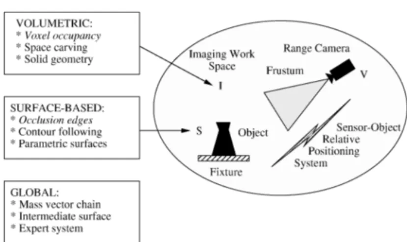
6. NON-MODEL-BASED VIEW PLANNING
It is convenient to classify existing view planning methods (most of which are non-model-based) by the domain of reason-ing about viewpoints—that is, volumetric,
surface-based, or global (Figure 5). Some methods combine several techniques. The majority fall into two subcategories— voxel occupancy or occlusion edges.
Fig. 5. Traditional non-model-based view planning methods.
6.1. Surface-Based Methods
Surface-based algorithms reason about knowledge of object surface space S.
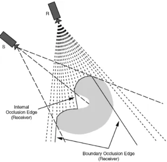
6.1.1. Occlusion Edge Methods
Occlusion edges. The most commonly used traditional method exploits geomet-ric jump edges. Illustrated in Figure 6, this approach is based on the premise that occlusion edges internal to the im-age indicate surface areas not yet sam-pled, while boundary jump edges rep-resent the boundary of the unobserved volume. In both cases, occlusion edges provide cues for the next-best-viewing direction.
Maver and Bajcsy. Some of the earliest papers using the occlusion edge method were by Maver and Bajcsy [1990, 1993]. Their approach was tailored to a long baseline laser profile scanner with a po-sitioning system limited to a single rota-tional degree of freedom. The two-stage method separately considered source and receiver occlusions. The focus was on finding and labeling boundary occlusion edges. View planning was done with ref-erence to a plane defined by the support fixture. The initial stage planned views as a rotation about the range camera boresight. The projection of occluded re-gions on the support plane was approx-imated by polygons. Occlusion-free arcs
were computed by a visibility analysis making assumptions about the height of each “shadow zone pixel.” A histogram was formed by summing the viewing arcs for each pixel and a next-best-view deter-mined from histogram maxima. The algo-rithm was computationally intensive due to the many-on-many visibility calcula-tions. Performance was sensitive to the un-derlying assumptions.
In a second view planning stage, de-scribed analytically but not implemented, occlusion edges of source shadow zones were used in a similar manner to deter-mine a new orientation for the camera ill-umination plane. The authors restricted the search for new scanning planes to the set perpendicular to the original scanning set up. Simulated results were shown.
The approach was limited by its
formu-lation as a 21/2D scene view rather than
a true 3D perspective. The scene was de-fined as a horizontal x- y array of pixels with a height value, either measured or as-sumed. Coupled with sensor and position-ing system limitations, the method was in-capable of acquiring an all-aspect model. Garcia et al. [1998a, 1998b] also utilized an occlusion edge method.
6.1.2. Contour Following. Once having lo-cated a portion of the object, the con-tour following technique involves “paint-ing” the object with the sensor by keeping
it in close proximity to the surface at all times. The technique has been applied to a class of range sensors with a limited sensing volume. Collision avoidance is a primary concern. Pudney [1994] described the application of contour following to a robot-mounted range sensor.
Conventional terminology labels range sensors as range “cameras,” implying an output in the form of an “image.” In fact, most range cameras are profile scan-ners which only acquire data in an image format through linear or rotational sen-sor motion by a fixed or programmable amount. Contour following usually in-volves acquiring long strips of profiles of an arbitrary length rather than a range
image in the conventional sense.4Because
the positioning systems used typically are accurate in pure translation but have lim-ited mobility or may require recalibration in rotation, scanning is frequently done along nonlinear curves with a fixed ori-entation. The technique is widely used commercially with mechanical CMM de-vices. Contour following works best with objects large in size relative to sensor coverage and for relatively simple shapes with smoothly flowing lines. It is more problematic with smaller objects and more complex shapes. Other contour following work with range sensors includes Soucy et al. [1998], Lamb et al. [1999], and Milroy et al. [1996]. The latter used a com-bined region growing and contour follow-ing strategy.
6.1.3. Parametric Surface Representations.
Superquadric models have been widely used in machine vision as flexible, com-pact representations. However, they are limited to simple scenes unless the scene is segmented and piecewise fitted with sep-arate models. Additionally, superquadrics are highly nonlinear.
Whaite and Ferrie. Related more to
robotic exploration than object recon-struction, the autonomous exploration ap-proach of Whaite and Ferrie [1990, 1991, 1992, 1997] nevertheless provides an in-4See also the discussion in Section 9.2.1.
teresting high-level perspective on charac-terization and exploitation of uncertainty in view planning. Their gaze-planning strategy used model uncertainty as a basis for selecting viewpoints. After the data is segmented, the task is to find superellip-soid parameters best describing each seg-mented part. They observed that the best sensor locations are those where the abil-ity to predict is worst—that is, where vari-ance in the fit of the data to the current model is greatest.
Because of concerns about the validity of the linearized theory, they took a conser-vative approach in which the sensor was always moved in small steps. Using a nu-merical analysis technique, they searched for and moved the sensor in the direction of maximum uncertainty. Movements were constrained to a view sphere at a fixed geodesic distance from the current scan-ner location. Experiments showed the al-gorithm to be attracted to regions of high object curvature.
The authors used a multilayered sys-tem design. A general-purpose, sensor-in-dependent, and environment-independent lower-layer navigator module handled view planning. A higher-level explorer
module contained application-specific
knowledge and handled executive-level functions such as delegating tasks, mon-itoring progress, making decisions, and resolving conflicts. While the layered design is attractive, it is difficult to see how detailed sensing and environmental factors can be separated from the act of sensor view planning.
The method directly incorporates mea-surements of sensor noise, although it is unclear exactly which noise sources are modeled or what the fidelity of the corre-sponding models is. View overlap is a con-sequence of the conservative nature of the search strategy rather than application of an explicit constraint.
While innovative and providing useful insights into view planning at a high-level of abstraction, the technique was designed more for approximate volumetric model-ing of simple scenes for robotic manip-ulation than for high-definition surface modeling.
6.2. Volumetric Methods
Volumetric methods select viewpoints by reasoning about the state of knowledge of imaging work space I . Each scan labels a portion of I . The NBV is the viewpoint of-fering the greatest prospective reduction in uncertainty about I . Volumetric meth-ods focus particularly on the solid shadows cast by the scanned object.
6.2.1. Voxel Occupancy Methods. Com-mon volumetric methods involve encoding space occupancy by a voxel occupancy grid or an octree.
Voxel occupancy grids. Voxelization is a widely used, compact means of encod-ing spatial occupancy. Voxel grids can also be used for a coarse surface repre-sentation, although they are clearly not suited for high-precision modeling. Their principal disadvantage is the large mem-ory requirement for even moderate vol-umetric quantization levels. In a typical imaging environment, the object occupies only a small portion of the imaging work space and its surface intersects an even smaller portion of the voxelized space. Most authors have ignored the impact of misalignment of spatial quantization in-tervals [Greespan 2002] between views. The phenomenon is similar to timing jit-ter in conventional time domain signal processing.
Banta et al. Banta and Abidi [1996] and Banta et al. [1995] defined the NBV as “the next camera pose which will extract the greatest amount of unknown scene in-formation.” Their objective is to minimize the number of views required. The work was similar to that of Connolly [1985] al-though they constrained the NBV search to a smaller search space. Both the imag-ing work space and object surface are rep-resented by voxel occupancy grids in which voxels are labeled occupied or unoccupied. Rather than allowing an “unknown” state, this binary approach labels all points not currently visible as occupied and merges views by a voxel-wise logical “AND” oper-ation. The papers explored several cuing mechanisms for suggesting feasible views,
including orienting the sensor in the di-rection of the viewpoint with the greatest number of potentially visible voxels based
on local surface exposure,5 the viewpoint
revealing the greatest number of hidden voxels based on a ray tracing visibility analysis, the mean of the three largest jump edges in the most recently acquired image, or the centroid of the cluster con-taining the largest number of unknown voxel faces.
The notion of applying several view planning concepts in combination under intelligent control is a useful contribution. The authors also proposed tests to ensure selection of a “good” NBV such as validat-ing by ray tracvalidat-ing that the feature of inter-est is actually visible and enforcing a min-imum angular separation between views on the view sphere. Additionally, they ex-amined several termination criteria, that is, terminating when the size of either the surface model or the occluded model ceases to change by a significant amount or when the ratio of the size of the sur-face model to that of the occluded model is “large.” However, the proposed termi-nation criteria do not relate to objective performance requirements for the target model.
The various algorithms attempted were effective in what could be called ex-ploratory, approximate view planning for topologically complex objects with purely synthetic data but were less effective in acquiring smaller geometric detail. While innovative, the work was subject to a number of simplifications and limitations. The range camera was treated as an error-free monostatic sensor with uniform performance within the imaging work space. Pose error was ignored. Viewpoints were restricted to a fixed-radius view sphere.
Massios and Fisher. A paper [Massios and Fisher 1998] summarizing Massios’ [1997] Master’s thesis built on previous voxel occupancy methods by using the weighted sum of visibility and “quality” 5 This is similar to Connolly’s “normal” algorithm which fails in concave regions.
factors as an NBV objective function:
ftotal(Ev) = wvfvisiblity(Ev)+wqfquality(Ev). (3)
The visibility cue was taken from an occlusion edge analysis finding occlusion plane voxels which are defined as unseen voxels with an empty neighbour.
Visibil-ity factor fvisiblity is set to the number of
occlusion plane voxels visible from view-ing direction Ev, as determined by ray trac-ing. The absolute value of the dot prod-uct of the estimated local surface normal and viewing direction vector is taken as a local quality measure for occupied vox-els. A region quality estimate is also for-mulated for each voxel due to unspecified
system inaccuracies. Quality factor fquality
is formulated to maximize the number of low-quality voxels visible from a given viewpoint.
Viewpoint space is taken to be a constant radius tesselated sphere, ob-tained by recursive subdivision of an icosahedron, fitted over the volumetric representation for the object. Using an experimental configuration whose posi-tioning system was limited to a single de-gree of freedom, the authors showed sep-arate and combined plots of the objective function as a function of angle and the cu-mulative number of views taken, a presen-tation format usefully illustrating the im-pact of the quality measure.
While the introduction of a quality term in the objective function was a valuable contribution, the chosen measure was sub-jective and did not relate to obsub-jective mea-surement constraints on the reconstructed model. Further, the model was determin-istic and considered only one error mecha-nism among several. Viewpoint space was constrained to two dimensions.
6.2.2. Octree Methods. Octree methods encode voxel occupancy more efficiently.
Connolly. One of the earliest papers on view planning was by Connolly [1985]. He appears to have first coined the term “next-best-view” (NBV). Connolly presented two algorithms, planetarium and normal, differing in the cue used to
suggest feasible views and the selection mechanism used to find the next-best-view from the set of feasible candidates. The imaging work space is voxelized and la-beled as empty, occupied, or unseen. This information is encoded in an octree which is also used to represent the object surface. All viewing vectors are assumed to point to the origin. Viewpoints are constrained to evenly spaced points on a sphere around the object.
The planetarium algorithm applies a visibility analysis of the octree for each candidate viewpoint on the sphere. The area of unseen voxels projected onto the image plane for each candidate viewpoint is taken as a measure of the solid angle of unseen space that will be swept by that view. The viewpoint with the largest un-seen area is selected as the NBV. The algo-rithm suffers from time complexity prob-lems inherent with a complete visibility analysis for all candidate viewpoints. The normal algorithm simplifies the visibility analysis to the local rather than global level by examining faces in the octree com-mon to both unseen and empty voxels. It is faster but does not deal as well with self-occluding scenes.
The method is subject to many sim-plifications and limitations. Neither sen-sor nor positioning system performance is characterized. The sensor is treated as an ideal point source without constraints on field-of-view or depth-of-field. Shadow ef-fects are ignored. Notwithstanding these limitations, Connolly’s pioneering concept of exploring and labeling imaging work space is found in many later papers.
6.2.3. Space Carving. The space carving
technique6 applies primarily to a small
class of range sensors with a limited sens-ing volume, particularly those designed as noncontact replacements for CMM me-chanical touch probes. The sensor is swept through the imaging work space in a preplanned methodical manner, diverting around obstacles, with the objective of 6 As used here, “space carving” is distinct from the shape from silhouette technique [Kutulakos and Seitz 2000].
reliably labeling work space occupancy. As with contour following, collision avoidance is a primary concern.
Papadopoulos-Orfanos. A paper by Papa-dopoulos-Orfanos and Schmitt [1997] su-mmarizing Papadopoulos-Orfanos’ [1997] Ph.D. research applied space carving to a specific shallow depth-of-field sen-sor for automated object reconstruction. Emphasis was placed on updating the voxel-based scene representation—in par-ticular, robust labeling of empty space to avoid collisions. Voxel labeling was achieved by a complex analysis of occlu-sion zones followed by ray tracing op-erations. Most of the work was concen-trated on collision avoidance and path planning.
Papadopoulos-Orfanos described but did not fully implement a two-stage 3D imaging strategy of scene exploration fol-lowed by surface data acquisition. The ex-ploration stage, which was implemented, employed an exhaustive search of un-known portions of the work space. In the vicinity of the object, the goal was to get the sensor as close as possible to the sur-face while avoiding collisions. During this phase, sensor orientation was fixed and only translations were employed to search the work space layer by layer in a zigzag pattern. As a consequence of the fixed ori-entation, occluded surfaces were not im-aged and surface occupancy in these re-gions was poorly defined. In a second stage of surface data acquisition (described but not implemented), sensor orientation view planning was proposed. Some existing NBV techniques were briefly discussed as candidate methods.
In its current form, the work does not address view planning per se. The explo-ration stage involves an exhaustive search of the imaging work space following a pre-planned trajectory modified by collision avoidance. No new view planning tech-nique is proposed. If more fully devel-oped, space carving has potential for high-precision scanning. However, it will likely remain slow as a consequence of the small sensor frustum and the exhaustive search technique.
Lamb et al. [1999] also utilized space carving at a coarse level of resolution in the first phase of a multistage approach to semiautomated model acquisition.
6.2.4. Solid Geometry Methods. This method utilizes standard solid geometry algorithms available with most CAD packages to model the current state of object knowledge. The method can be robust with respect to complex topology. A generic problem with the technique arises from solid geometry intersection operations which, by definition, subtract and cannot add volume. Therefore, if a range image used to extrude a solid volume does not completely cover the object, the resulting volume will exclude a portion of the object which can never be recovered by subsequent intersection op-erations. Consequently, difficulties arise when a view fails to completely enclose the object or along occlusion boundaries where data is often missing or erroneous due to inclination and edge effects.
Bistatic shadow effects. Although ig-nored by many authors, a triangulation-based laser scanner is a bistatic sen-sor whose optical baseline is generally significant with respect to the measure-ment stand-off distance. Therefore, the shadow effect is nonnegligible and has two components—source and receiver shad-ows. Bistatic shadow effects are illus-trated in Figure 6. We can observe that an occlusion edge as seen by the receiver may lie inside the object. This poses diffi-culties for occlusion-edge-based view plan-ning techniques employing solid geometry intersection operations. Collision avoid-ance routines operating in conjunction with view planning also need to make al-lowance for this fact. Further, in general, the object will not lie entirely within the camera frustum, so a given range image may or may not contain boundary occlu-sion edges. Some NBV algorithms can fail in the absence of occlusion edges.
Reed. In a series of articles by Reed and Allen [1997, 1999] and Reed et al. [1997a, 1997b] arising from Reed’s [1998] Ph.D.
Fig. 6. Occluding edges in geometric images with bistatic sensor.
thesis, a solid geometry approach was used to synthesize a continuous 3D viewing vol-ume for a selected occlusion edge, rather than discretizing viewpoint space. A mesh surface was created for each range image and each mesh triangle was swept to form a solid model. Solid geometry union oper-ations on the swept volume resulted in a composite model comprised of the surface and occluded volume, as known at that stage of modeling. Surfaces on the compos-ite model were labeled imaged surface or
occluded surface.
Reed’s view planning approach then proceeded with manual selection of a spe-cific occluded edge as a target. A “visibil-ity volume” was calculated for the target— that is, a 3D volume specifying the set of all sensor positions having an unoc-cluded view of the entire target for the model as presently defined. This was com-puted by subtracting the occlusion volume for each model surface component from the target’s unoccluded volume, a half-space whose defining plane was coinci-dent with the target’s face and oriented in the appropriate direction. The work was based on previous sensor planning work in the same lab by Tarabanis et al. [1996].
The volumetric approach allowed sensor and positioning system constraints to be added.
The 3D imaging workspace search was an improvement over methods con-strained to an arbitrary 2D surface around the object. The authors claimed their ap-proach had the advantage of defining more accurate viewpoints due to the treatment of viewpoint space as continuous rather than discrete, although no analytical or experimental data were provided to quan-tify this assertion.
Part of the reported research [Reed et al. 1997a] relied on manual selection of a suit-able target and hence the NBV. There was no discussion of the sensitivity of the al-gorithm to target occlusion edge selection. A second paper [Reed et al. 1997b] dis-cussed an approach to automated view-point selection. In this case, the algorithm selected the NBV as the one imaging the most occluded surface elements in the cur-rent composite model. The NBV was de-termined by computing the visibility vol-ume for each occluded surface element, intersecting each visibility volume with the sensor’s reachable space and search-ing the intersection for the point imagsearch-ing
the most surface area. A third paper [Reed and Allen 1999] briefly examined NBV planning based on the use of multiple targets.
Benefits of solid geometry methods include robustness to complex object topology and the guarantee of water-tight models. Viewpoint synthesis can be computationally advantageous with re-spect to methods which discretize view-point space. However, as presently de-fined, the approach has limitations. The sensor frustum is only partially modeled— field-of-view constraints are not consid-ered. Bistatic shadow effects on view plan-ning are not addressed directly, although missing data in small shadow zones is dealt with by interpolation and along oc-clusion boundaries by surface extension along the direction of the sensor baseline. Sensor errors are only briefly considered. View overlap planning is not addressed. Set operations on extruded surface ele-ments introduce artifacts along integra-tion boundaries.
6.3. Global View Planning Methods
A few methods derive a view planning cue from global rather than local characteris-tics of the geometric data.
6.3.1. Mass Vector Chain. Yuan [1993, 1995] described an interesting view plan-ning mechanism. He observed that “a reconstruction system expects a self-controlled modeling mechanism for the system to check the spatial closure of ob-ject models and to estimate the direction of unprocessed features” [Yuan 1995, p. 307]. Illustrated in Figure 7, his approach segments the observed surface into a set of small patches and describes the object with a mass vector chain (MVC). By def-inition, an MVC is a series of weighted
vectors. A mass vector EVi is assigned to
each surface patch Si of the object. Thus,
E
Vi = EniRi, where Eni is the average
vis-ible direction and Ri is the surface size
when viewed from that direction. It is eas-ily shown that the boundary surfaces of an object compose a closed surface bound-ary only when their mass vectors form
Fig. 7. Mass vector chain.
a closed chain. Thus, the next-best-view can be set to the negative of the cumu-lative MVC, which should define a view-ing direction whose mass vector will close the chain or at least shorten the gap. Special rules are required for holes and cavities.
The algorithm was shown to work with synthetic geometric data for a simple object. However, the idealized imaging environment does not address the com-plications of modeling automation with real sensors and complex humanly made or natural objects. The method is capa-ble only of estimating viewing direction, not position. It has no reliable measure of scale, range, or imaging volume. The method is able to deal with moderately complex topology and may have poten-tial for machine vision tasks involving hu-manly made parts with simple shape or for the initial global view planning phase of a two-step coarse-fine planning process.
6.3.2. Intermediate Space Representations.
The essence of view planning is capturing, representing, and optimizing measures of visibility of the object surface from sensor poses in viewpoint space. This mapping between the object surface and points in
the workspace of the sensor and position-ing system involves a large amount of in-formation and therefore a high degree of computational complexity for its acquisi-tion, storage, and manipulation. It is de-sirable to find a more compact and easily searched representation of the visibility information with a minimum loss of in-formation. One approach following this line of reasoning involves encoding visibil-ity information on a virtual surface posi-tioned between the object and the sensor workspace—that is, an intermediate space
representation.
Positional space—Pito. Pito’s [1997a] thesis is significant for its contributions to all four aspects of geometric modeling automation (scanning, registration, in-tegration, and view planning). See also the summary paper [Pito 1999] as well as Pito [1996a, 1996b, 1997b] and Pito and Bajcsy [1995].
Pito’s work is unusual in that he took pains to characterize performance of the range scanner used for experiments and then incorporated sensor models in the au-tomation algorithms. In addition to treat-ing the graztreat-ing angle effect (fairly com-mon in the literature), he also treated edge effect anomalies during the integra-tion phase. The view overlap requirement was incorporated. The shadow effect was explicitly treated. However, nonstation-ary measurement error within the mea-surement volume was not addressed. The need for generalized viewpoints was dis-cussed but apparently not implemented. The technique is amenable to using gen-eralized viewpoints, at the expense of in-creasing the dimensionality of intermedi-ate space.
Like many others before him, Pito chose occlusion edges as a cuing mechanism for the NBV search. He observed that the void volume can be economically repre-sented by defining only the void surface near edges of the current model, which he represented by small rectangular patches attached to occluding edges of the seen surface. He argued that it is unnecessary to represent the complete boundary of the umbra cast by the object. In general, the
portion of the umbra nearest the occlusion boundary will be nearest to the real object surface and therefore be the best region to search next. Furthermore, such regions fit the overlap constraint.
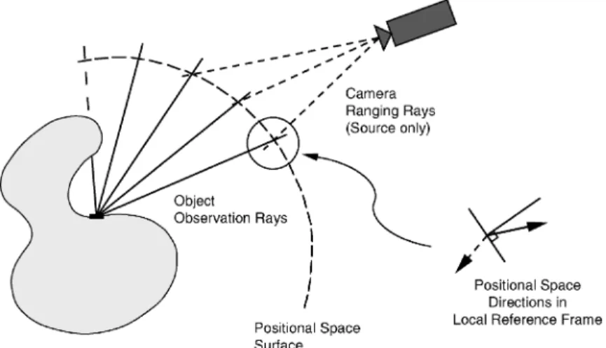
Illustrated in Figure 8, Pito’s NBV al-gorithm used an intermediate space rep-resentation, “positional space” (PS), as a repository for two types of visibility information—object surface visibility and sensor scanning potential. A virtual posi-tional space surface (PSS), with a shape appropriate to the sensor-positioning sys-tem combination, was placed between the object and the sensor workspace. Object surface space (represented as a mesh), PSS, and viewpoint space were dis-cretized.
The visibility of each triangular mesh element on the object surface can be en-coded in positional space by tracing an “observation ray” from the mesh element to a PSS cell. The direction of an unoc-cluded observation ray relative to a lo-cal frame of reference on the PSS can be specified by two angles, termed the
posi-tional space direction(PSD). Pito chose to encode surface visibility as an analogue value equal to the area of the surface element visible by a given ray weighted by a confidence measure tied to the mea-surement grazing angle. Thus, PS was a scalar field in four dimensions P (u, v, θ, φ) where u, v were coordinates in PSS and θ, φ were the components of PSD. Encod-ing the image of both the seen surface and void patches in PS provided a means to ap-ply an overlap constraint between views to meet registration and integration re-quirements. The range camera’s scanning potential at a given viewpoint can be simi-larly encoded in positional space by deter-mining the intersection of “ranging rays” from the optical transmitter and receiver with the PSS. A separate image was cal-culated for each viewpoint. Using PS as a placeholder for ranging and observation rays facilitated determining which of them were collinear, as well as aiding the appli-cation of NBV constraints.
Without detracting from the compre-hensive treatment and contribution of the work, there are some unresolved issues
![Fig. 2. Conventional active triangulation. (From El- El-Hakim and Beraldin[1994]; c °IEEE 1994.)](https://thumb-eu.123doks.com/thumbv2/123doknet/14196357.479135/5.918.471.759.144.388/fig-conventional-active-triangulation-el-hakim-beraldin-ieee.webp)