Publisher’s version / Version de l'éditeur:
Vous avez des questions? Nous pouvons vous aider. Pour communiquer directement avec un auteur, consultez la
première page de la revue dans laquelle son article a été publié afin de trouver ses coordonnées. Si vous n’arrivez pas à les repérer, communiquez avec nous à [email protected].
Questions? Contact the NRC Publications Archive team at
[email protected]. If you wish to email the authors directly, please see the first page of the publication for their contact information.
https://publications-cnrc.canada.ca/fra/droits
L’accès à ce site Web et l’utilisation de son contenu sont assujettis aux conditions présentées dans le site
LISEZ CES CONDITIONS ATTENTIVEMENT AVANT D’UTILISER CE SITE WEB.
Inter-Noise 2010: 13 June 2010, Lisbon, Portugal [Proceedings], 2010-06-13
READ THESE TERMS AND CONDITIONS CAREFULLY BEFORE USING THIS WEBSITE. https://nrc-publications.canada.ca/eng/copyright
NRC Publications Archive Record / Notice des Archives des publications du CNRC :
https://nrc-publications.canada.ca/eng/view/object/?id=2cb767ce-6412-46b6-a3da-d640940e38df https://publications-cnrc.canada.ca/fra/voir/objet/?id=2cb767ce-6412-46b6-a3da-d640940e38df
NRC Publications Archive
Archives des publications du CNRC
This publication could be one of several versions: author’s original, accepted manuscript or the publisher’s version. / La version de cette publication peut être l’une des suivantes : la version prépublication de l’auteur, la version acceptée du manuscrit ou la version de l’éditeur.
Access and use of this website and the material on it are subject to the Terms and Conditions set forth at
Approaches for estimating flanking transmission for heavy impact
sources
http://www.nrc-cnrc.gc.ca/irc
Approa c he s for e st im a t ing fla nk ing t ra nsm ission for he a vy im pa c t
sourc e s
N R C C - 5 3 5 6 5
S c h o e n w a l d , S . ; N i g h t i n g a l e , T . R . T . ; Z e i t l e r ,
B . ; K i n g , F .
J u n e 2 0 1 0
A version of this document is published in / Une version de ce document se trouve dans:
InterNoise 2010, Lisbon, Portugal, June 13-16, 2010, pp. 1-10
The material in this document is covered by the provisions of the Copyright Act, by Canadian laws, policies, regulations and international agreements. Such provisions serve to identify the information source and, in specific instances, to prohibit reproduction of materials without written permission. For more information visit http://laws.justice.gc.ca/en/showtdm/cs/C-42
Les renseignements dans ce document sont protégés par la Loi sur le droit d'auteur, par les lois, les politiques et les règlements du Canada et des accords internationaux. Ces dispositions permettent d'identifier la source de l'information et, dans certains cas, d'interdire la copie de documents sans permission écrite. Pour obtenir de plus amples renseignements : http://lois.justice.gc.ca/fr/showtdm/cs/C-42
APPROACHES FOR ESTIMATING FLANKING
TRANSMISSION FOR HEAVY IMPACT SOURCES
Stefan Schoenwald; Trevor Nightingale; Berndt Zeitler; Frances King
Affiliation: {NRC Canada; NRC Canada; NRC Canada} e-mail: {[email protected], [email protected],
[email protected], [email protected]}
Abstract
Flanking transmission exists in all buildings and its importance relative to direct transmission is determined by the quality of the acoustical design. The ISO 10848 standard has been created to provide estimates flanking transmission from airborne and the ISO tapping machine. Currently this method is unproven for impact flanking transmission at low frequencies, especially from heavy/soft impact sources like the “bang machine” and “rubber ball” impact sources. This paper assesses three methods. The first and straight forward method obtains results by suppressing all transmission paths except for the one(s) of interest. The second obtains results by using two sets of data (one including the transmission path(s) of interest and the other not) and indirectly assigning the change in transmitted sound power to the path(s) suppressed. The third, a new approach, is presented that is found to be considerably more accurate and easier to apply when flanking elements and junction are symmetric. Results for the various approaches are presented when applied to wood-frame construction, and limitations of each approach are discussed.
Keywords: Building acoustics, wood frame, impact sound, flanking transmission.
1 Introduction
A standardized protocol for measuring flanking sound transmission for airborne and light impact sources is given by the so-called “indirect” measurement method in ISO 10848 [1]. This paper is primarily concerned with the measurement of impact flanking sound transmission generated by the “bang-machine” or the “ball” heavy impact sources (JIS A 1418-2, and KS F 2810-2). Unfortunately, the ISO 10848 protocol is not feasible - especially, for heavy impact sources.
This paper presents a new protocol for measuring sound transmission of flanking paths, and discusses the basic assumptions and limitations of the method.
The flanking paths considered in this paper are “first order flanking paths”. There is one building element in the source room (in our case always the floor) which is excited and one building element in the receive room from which sound is radiated, and both of these elements are coupled at a single junction. For wood frame construction that exhibit significant propagation attenuation, second order paths which involve transmission across multiple junctions tend to be negligible relative to first order paths.
2
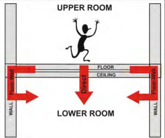
1.1 Relevant Flanking Paths for Impact Transmission
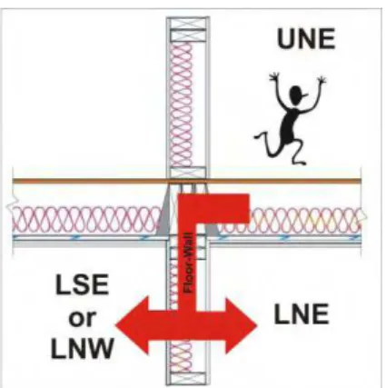
This paper considers transmission between rooms that are vertically adjacent. When the floor is excited by an impact source in the upper room, there will be five transmission paths - one direct path through the ceiling and one floor-wall flanking path per junction as indicated in Figure 1. For wood frame construction the four flanking paths can be grouped into two pairs, one pair for the non-load bearing junction (where the joists are parallel to the junction) and the load-bearing junction (where the joists are perpendicular to the junction). Thus, only estimates of sound transmission through three paths are necessary to obtain an estimate of apparent impact sound isolation between the upper and the lower room:
1. Direct path (floor-ceiling) through the floor-ceiling assembly 2. Flanking path (floor-wall) through the load bearing (LB) junction 3. Flanking path (floor-wall) through the non-load bearing (NLB) junction
Figure 1: Relevant flanking paths for impact sound transmission for vertically adjacent rooms
1.2 Specimen in NRC-IRC Flanking Facility, TH7
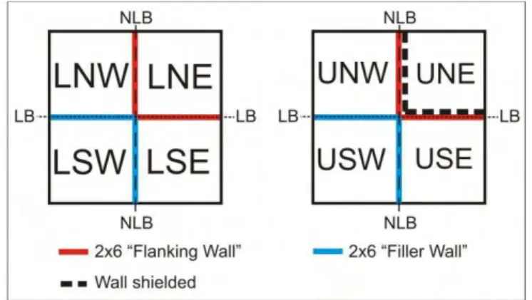
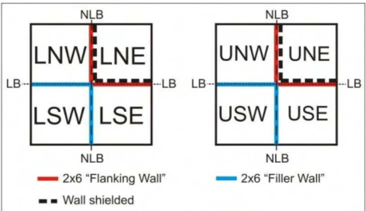
Measurements were made in the NRC-IRC Flanking Facility, which enables estimation of flanking paths between any of the 8 rooms, 4 on each of the two levels. As shown in Figure
2 we are interested in characterizing two floor-wall flanking paths – one for the load-bearing
junction and one for the non-load bearing junction.
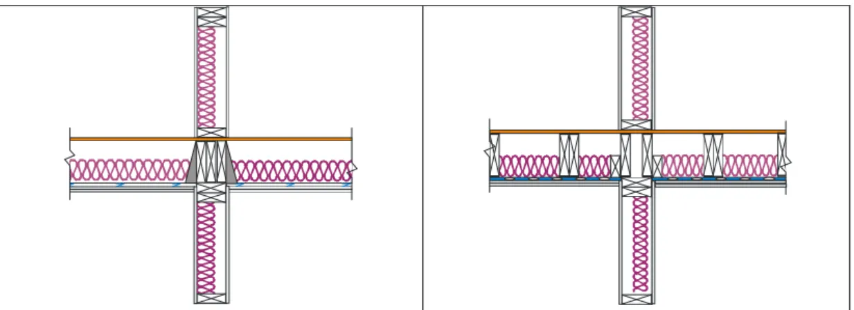
The two north-east rooms (LNE and UNE) were chosen and the 4 partition walls of these rooms were fabricated as shown in Figure 3. The cladding of the other walls do not influence the floor-wall flanking paths of interest, so these surfaces were finished with a double layer of 16 mm Type X gypsum board supported by resilient channels. The ceiling in the other rooms have no effect on the flanking paths of interest so these ceilings were finished with 3 layers of 16 mm Type X gypsum board mounted on resilient channels.
Sketches showing the construction details are given in Figure 3. A topping consisting of 16 mm plywood and 36 mm of gypsum board was applied to the floor surface only in the UNE room. For the purposes of this paper the exact details of the walls, floors, and junctions are not as important as the symmetry that is involved, as will be discussed in the later sections.
Figure 2: Orientation and notation of rooms and wall assemblies in NRC-IRC Flanking Facility. The first letter indicates the level, lower (L), or upper (U). The second and third letters indicates the cardinal orientation north (N), east (E), south (S), west (W). The walls
are identified as being load bearing (LB), or non-load bearing (NLB).
Figure 3: Load bearing junction (left) and non-load bearing junction (right) under test. The walls under test are identified in Figure 2 by the red lines.
2 Measurements of Flanking Transmission
There are three approaches to measure flanking transmission due to impact excitation of the floor. The first two were either not practical, or provided a very conservative estimate of flanking sound isolation. However, an outline and discussion of these methods is necessary since they form a basis of understanding how flanking was measured by applying the third more sophisticated method, the focus of this paper.
2.1 Indirect Method of ISO 10848
This method was not applied in this project for reasons discussed below. Despite this the approach of the method is briefly outlined because it is basis of a modified shielding method presented later.
According to the indirect method of ISO 10848 only one vertical room pair is needed to measure the direct path and both flanking sound transmission paths that are relevant for this study. ISO 10848 suggests measuring transmission by suppressing transmission of all paths
4
except the one of interest. For airborne sound transmission, path estimation is usually achieved by shielding surfaces of all other building elements in both the source and receive room that are not part of the path of interest.
For impact transmission shielding in the source room is usually not necessary since the floor is excited directly with an impact source. To characterize all flanking paths of interest, impact sound pressure levels must be measured for three different shielding conditions. Shielding consisted of additional layers of gypsum board and glass fibre batts placed in front of the building element for which the transmission path is to be suppressed. There is no rigid connection to the test specimen.
Measurement of the flanking paths of interest is not possible using the ISO 10848 protocol for several reasons. First, it is extremely difficult to shield the ceiling in the lower room to suppress direct impact sound transmission. Second, direct transmission is much greater than flanking transmission along a single path. Hence the shielding would have to provide a very high degree of sound isolation in the low frequency range which is impractical for lightweight shielding.
2.2 Modified shielding approach
A second method referred to as the modified shielding approach has been developed in previous NRC-IRC Flanking Studies [2,3], but requires an extremely high degree of measurement repeatability.
The method is similar to the ISO 10848 indirect method discussed earlier, but sound transmission is not measured separately for all paths. Instead contributions of specific paths are estimated by attributing the contribution of specific flanking paths to changes in the measured sound transmission for different shielding conditions.
As an example, the floor wall flanking paths would be evaluated by measuring the impact sound pressure level in the receive room without any shielding in place. Next, the measurement is repeated with one of the two flanking walls in the lower room shielded. From the difference of the two measurement results, it is possible to obtain an estimate of the sound transmission through the paths that involve the building element that was shielded. While this method requires less effort than the “indirect method” of ISO 10848, it does have some limitations. First, the heavy impact sound pressure level Li,f,max measured according to
JIS 1418-2 or KS F 2810-2 is not independent of the receive room absorption condition [4]. When any shielding approach is applied, it must be ensured that the receive room volume and/or the absorption condition is not changed by the added shielding. This is not an issue for test methods that measure the transmitted power (e.g., ISO 140-3, or 140-6) as they normalize to both the receive room volume and absorption, but the measured Li,F,max is not
normalized. So it is not known if the measured change is due to changes in the receive room absorption and volume, or the flanking path that was suppressed. In theory the recently developed normalization approach developed [4] could account for this, but as we discuss next a very high degree of measurement precision is required for this method to be viable. Second, an accurate estimate of the contribution of a path can only be obtained with this method if the difference in the impact sound transmission for the two shielding conditions is significantly larger than the uncertainty associated with the measurement repeatability. The uncertainty of measured Li,F,max in repeated tire drop tests is much bigger than for
instance of light impact tests. Hence, small differences in the Li,F,max for two different
shielding conditions cannot necessarily be related to a change of the sound transmission due to adding or removing shielding, but may also be due to the uncertainty of the measurement
results. To get a conservative estimate for single paths it is sensible to use a 1 dB threshold and it is assumed that smaller differences in heavy impact sound isolation cannot be measured. In frequency bands where the change is less, it is assumed that the change is just below the threshold of resolution (about 1 dB) and the Li,F,max of the shielded path is at
least 6 dB smaller. A more accurate estimate of the path is not possible.
This approach is shown for the example of the test specimen. The two shielding conditions necessary are shown in Figure 4 and Figure 5.
Figure 4: Shielding Condition 1- only load-bearing and non-load bearing wall in Room UNE on upper level are shielded.
Figure 5: Shielding Condition 2- load-bearing and non-load bearing wall in Room LNE on lower level and Room UNE on upper level are shielded
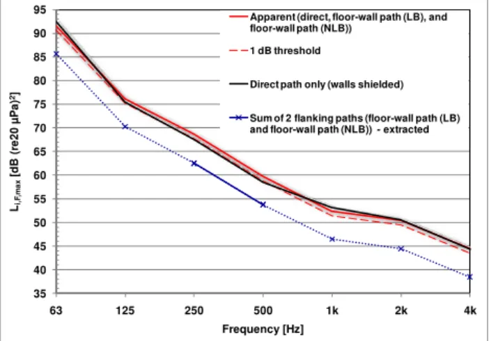
The measurement results and the path estimate are presented in Figure 6. First, the apparent impact sound pressure level is measured between the vertically adjacent room pairs. The transmission includes the direct path, one floor-wall path across the load bearing junction, and one floor-wall path across the non-load bearing junction. Next, the measurement is repeated when both walls of the specimen in the lower room are shielded to give an estimate of the direct path.
Since the receive room volume and reverberation time had changed due to the shielding, the estimate of the direct path is normalized [4]. Nevertheless, the difference of the two impact sound pressure levels is rather small, and in some octave bands (63 Hz and 1 kHz) adding the shielding increased the impact sound pressure level. This should not be physically possible and indicates that the uncertainty in repeated measurements and the normalization correction is bigger than the actual change in sound isolation.
6
Further, the applied 1 dB threshold is shown in Figure 6. Only in the 250 Hz and 500 Hz octave band the Li,F,max is slightly smaller than the applied threshold and the total contribution
of the two flanking-paths can be extracted safely from the change of Li,F,max. In the remaining
frequency range the conservative estimate indicated by the dashed blue line has to be used. Thus, only very conservative estimates of flanking transmission can be obtained with this method for the current test specimen since the difference between direct transmission and the sum of direct and flanking transmission is rather small, and smaller than the uncertainty in the measurement repeatability.
Figure 6: Heavy impact sound isolation between Room UNE and LNE showing measured apparent and direct impact sound pressure level as well as conservative estimate for the
sum of one load-bearing and one non-load bearing floor-wall path
2.3 Symmetry approach
This is the more sophisticated approach that was applied to measure the floor-wall flanking paths. A number of assumptions were made which are now outlined. Construction details of the two junctions under test are shown in Figure 3. From the two drawings, it can be seen that for both junctions all the structural members that define the junction and determine the structure-borne sound transmission through it, namely the floor framing, the subfloor, and the wall framing, are symmetric about the vertical axis of the walls.
Since the walls are single stud, and have the same gypsum board and number of layers on either side, the walls are symmetric, too. This symmetry enables one to assume that when the wall is excited by the junction with the floor, the wall will have the same space average structural velocity on both leaves. Again because of symmetry, the radiation efficiency of both sides will be identical, so too will the radiated sound power. Thus it is possible to estimate flanking transmission for the floor-wall path between vertically adjacent rooms by measuring the floor-wall path between diagonally adjacent rooms when the wall and the junction are symmetric.
This symmetry is used to obtain an estimate of the flanking impact sound transmission through the floor-wall path of the load-bearing and non-load bearing junction. The impact sound pressure level of the floor-wall path is measured in the rooms on the diagonal (LSE and LNW) instead of in the room LNE directly below the source room as shown in Figure 7.
35 40 45 50 55 60 65 70 75 80 85 90 95 63 125 250 500 1k 2k 4k Li, F ,m a x [d B (r e 2 0 µ Pa ) 2] Frequency [Hz]
Apparent (direct, floor-wall path (LB), and floor-wall path (NLB))
1 dB threshold
Direct path only (walls shielded)
Sum of 2 flanking paths (floor-wall path (LB) and floor-wall path (NLB)) - extracted
Figure 7: Illustration of symmetry approach - flanking transmission via the floor-wall path is equal for vertical adjacent rooms and rooms on the diagonal
However, the impact sound pressure level measured in the diagonal rooms, LSE and LNW, cannot directly be used as an estimate of the floor-wall paths. Careful data processing is necessary to ensure, that:
The measured impact sound pressure level in the two rooms on the diagonal is purely due to transmission through the path of interest – the floor-wall path. Other flanking paths, like the floor-ceiling, may contribute to the measured sound pressure level in the rooms on the diagonal.
The measured impact sound pressure level in the two rooms on the diagonal is not contaminated by airborne sound transmission through the partition wall. There will be high sound pressure levels in the low frequency range in the LNE room due to the direct transmission through the floor-ceiling assembly. Part of this sound power is also transmitted through the partition walls to the LSE and LNW rooms and may contribute to the measured sound pressure level in the rooms on the diagonal. The measured impact sound pressure level in the two rooms on the diagonal is
normalized to the appropriate volume and absorption before it is used further. The volume and absorption condition of the diagonal receive rooms are different
(VLNE 43 m3, VLSE 41 m3, and VLNW 37.5 m3 ) and sound pressure levels must be
normalized[4] before the estimate of the floor-wall path measured on the diagonal can be added to other paths.
The first issue, adequate suppression of other transmission paths, was dealt with by there being multiple layers of resiliently mounted gypsum board on both the ceiling and sidewalls as already noted. These paths are considerably less important than the path from the floor to the wall on the diagonal – the path of interest.
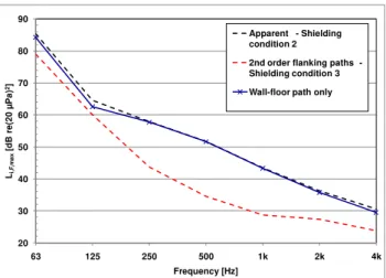
To confirm this, shielding approach of Section 2.2 was applied. It works very well for this case since the change in shielding condition shown in Figure 8 and Figure 9 causes a very significant change in the measured sound pressure level as shown in Figure 10. Thus, the contribution of flanking paths other than the floor-wall paths was negligible.
8
Figure 8: Shielding condition 2 with load-bearing and non-load bearing wall in Room LNE on lower level and in Room UNE on upper level shielded
Figure 9: Shielding condition 3 - load-bearing wall in Room LSE and non-load bearing wall in Room LNW on lower level and both walls in Room UNE on upper level shielded
In a second step this contribution is subtracted from the measurement results of the shielding condition shown in Figure 9 when the surface of the Flanking Wall in room LSE and room LNE is unshielded to obtain estimates of the sound transmission of the floor-wall path. In this case, normalization of the measurement results was not necessary because the change of the receive room properties due to adding the shielding was negligibly small. The estimate of the impact sound pressure level due to pure transmission via the floor-wall path is also given in Figure 10 for the load bearing junction of the specimen in Figure 3.
This procedure also corrects possible contamination of the signal due to indirect airborne sound transmission through the partition walls. This is accomplished by moving the shielding to the opposite side of the wall, so that for both shielding conditions shown in Figure 8 and
Figure 9 the airborne transmission loss between rooms LNE and LNW, as well as LNE and
LSE respectively, is the same. Further measurements of airborne transmission have shown that the sound isolation between the lower rooms is approximately the same for both configurations and thus also the contamination due to indirect airborne sound transmission is taken into account in the correction.
Estimates for the two floor-wall flanking transmission paths were obtained with and without the plywood-gypsum board floor topping using the symmetry approach and are presented for the bare subfloor in Figure 11 and for the topping in Figure 12. Both with and without the topping, flanking impact sound transmission is more important for the load bearing junction than for the non-load bearing junction.
Figure 10: Impact sound pressure level Li,F,max measured with the bang machine for
transmission across the load bearing junction for specimen shown in Figure 3 with contribution of all flanking paths including the indirect airborne sound transmission path.
Inspection of the figures suggests that the topping is more effective at controlling flanking transmission that involves a load-bearing junction than nominally the same floor-wall path that involves a non-load bearing wall. This can be explained by recognizing when the topping is added it often reduces propagation attenuation across the floor and more vibration energy can reach the non-load bearing junction relative to the bare floor. In extreme cases this change in propagation attenuation is greater than the change in power injection, and flanking gets worse when the topping is added. For the direction parallel to the joists propagation is relatively much lower because the joists channel the vibration energy, and relative to the bare floor adding a topping does not change attenuation in this direction nearly as much.
3 Discussion and conclusions
The practicality of applying the “indirect method” of ISO 10848 depends on two primary factors. First the practicality of shielding all the transmission paths except the one of interest. Clearly it is impractical to shield a ceiling so an alternative to the indirect method is needed to characterize impact flanking transmission from floor to wall in the room below. The modified shielding approach, which is a variant of the indirect method, is an excellent alternative if repeatability of the measurement method is sufficiently good. Realistically, the repeatability of the test method must be better than about 1.0 dB, and ideally 0.5 dB. This will likely require an automated measurement system to ensure the microphone positions are nominally identical for each test. Also the excitation source must be very repeatable, too. Airborne and the ISO tapping machine impact sources are sufficiently repeatable sources. However, the bang machine seems not to provide the necessary precision for wood frame construction, perhaps due to non-linearities in the floor response. Further investigation is required to develop a suitable method to normalize the fast-weighted peak sound pressure level, so that results from JIS A 1418-2 and KS F 2810-2 measured in different laboratories can be compared.
Fortunately, many wood frame constructions are symmetric and the approach proposed in this paper provides a useful method to eliminate or minimize the effect of direct transmission. However, shielding may still be required if other flanking paths are present in order to obtain a more accurate estimate of flanking transmission.
20 30 40 50 60 70 80 90 63 125 250 500 1k 2k 4k Li, F ,m a x [d B r e (2 0 µ Pa ) 2] Frequency [Hz] Apparent - Shielding condition 2
2nd order flanking paths -Shielding condition 3 Wall-floor path only
10
Figure 11: Measured Flanking impact sound pressure level Li,F,max of wall-floor path for the
bang machine, bare subfloor. Path estimates and total flanking for vertical room pair.
Figure 12: Measured flanking impact sound pressure level Li,F,max of wall-floor path for the
bang machine, topping. Path estimates and total flanking for vertical room pair.
References
1 “Acoustics -- Laboratory measurement of the flanking transmission of airborne and impact sound between adjoining rooms,” ISO 10848, International Standards Organisation, 2006.
2 “Flanking Transmission in Multi-Family Dwellings: Phase IV,” Nightingale, T.R.T.; Quirt, J.D.; King, F.; Halliwell, R.E. Research Report, NRC Institute for Research in Construction, 218, pp. 425. 2006-03-01.
3 ”Characterizing flanking transmission paths in the NRC-IRC Flanking Facility” King, F.; Schoenwald, S.; Sabourin, I., Canadian Acoustics, Vol.37(3), p.50-51, 2009
4 “Influence of receive room properties on impact sound pressure level measured with heavy impact sources” Schoenwald, S.; Zeitler, B.; Nightingale, T.R.T. King F., NRC-IRC Research Report 303, 2010.
15 25 35 45 55 65 75 85 63 125 250 500 1k 2k 4k Li, F ,m a x [d B r e (2 0 µ Pa ) 2] Frequency [Hz]
Wall-floor path (Load Bearing) Wall-floor path (Non Load Bearing)
Total Flanking - sum of 2 Load Bearing and 2 Non Load Bearing
15 25 35 45 55 65 75 85 63 125 250 500 1k 2k 4k Li, F ,m a x [d B r e (2 0 µ Pa ) 2] Frequency [Hz]
Wall-floor path (Load Bearing) Wall-floor path (Non Load Bearing)