Publisher’s version / Version de l'éditeur:
Vous avez des questions? Nous pouvons vous aider. Pour communiquer directement avec un auteur, consultez
la première page de la revue dans laquelle son article a été publié afin de trouver ses coordonnées. Si vous n’arrivez pas à les repérer, communiquez avec nous à PublicationsArchive-ArchivesPublications@nrc-cnrc.gc.ca.
Questions? Contact the NRC Publications Archive team at
PublicationsArchive-ArchivesPublications@nrc-cnrc.gc.ca. If you wish to email the authors directly, please see the first page of the publication for their contact information.
https://publications-cnrc.canada.ca/fra/droits
L’accès à ce site Web et l’utilisation de son contenu sont assujettis aux conditions présentées dans le site LISEZ CES CONDITIONS ATTENTIVEMENT AVANT D’UTILISER CE SITE WEB.
13th Annual Conference on Computational and Fluid Dynamics [Proceedings],
2005
READ THESE TERMS AND CONDITIONS CAREFULLY BEFORE USING THIS WEBSITE.
https://nrc-publications.canada.ca/eng/copyright
NRC Publications Archive Record / Notice des Archives des publications du CNRC :
https://nrc-publications.canada.ca/eng/view/object/?id=8c6dcc97-e8b8-46d1-9094-6817be4067a9 https://publications-cnrc.canada.ca/fra/voir/objet/?id=8c6dcc97-e8b8-46d1-9094-6817be4067a9
NRC Publications Archive
Archives des publications du CNRC
This publication could be one of several versions: author’s original, accepted manuscript or the publisher’s version. / La version de cette publication peut être l’une des suivantes : la version prépublication de l’auteur, la version acceptée du manuscrit ou la version de l’éditeur.
Access and use of this website and the material on it are subject to the Terms and Conditions set forth at
Numerical simulation of 3-D turbulent flow through entire stage in a
multistage centrifugal pump
Numerical Simulation of 3-D Turbulent Flow through
Entire Stage in a Multistage Centrifugal Pump
Si Huang1, Mohammed F. Islam2 and Pengfei Liu2
1
Department of Industrial Equipment and Control Engineering, South China University of Technology, Guangzhou, China 510641
2
Institute for Ocean Technology, National Research Council Canada St. John’s, NL, A1B 3T5, Canada
Email: Mohammed.Islam@nrc-cnrc.gc.ca
A
BSTRACTA three-dimensional turbulent flow through a multistage centrifugal pump is numerically simulated using a commercial CFD software package. The simulation and analysis include flow fields in rotating impeller and stationary diffuser and is completed in a multiple reference frame. The standard k-ε turbulence model is applied. The analysis of the simulation reveals that the reverse flows exist in the zone near the impeller exit and diffuser entrance, resulting in flow field asymmetric and unsteady. There is a considerable interference on velocity field at impeller exit due to the interaction between impeller blades and diffuser vanes. The hydraulic performance is connected and evaluated with the 3-D computational flow field. The current computation is verified by comparing predicted and measured head.
1. I
NTRODUCTIONMultistage centrifugal pumps, as high-pressure boosters and big power consumers, are widely applied in various engineering fields all over the world (Figure 1 shows a typical 5-stage feeding pump as analysis object of this research work). It is potential to generate a significant economic benefit with performance improvement by means of design and manufacture for multistage pumps. Both impellers and diffusers inside a pump are the parts playing a key role on its performance, so they are usually the objects for studying and revising. Due to the complexity of the mechanical structure and the coexistence of rotating part and stationary part, nature of flow through a whole pump stage passages and the relation between internal flow field and pump performance are still uncertain. The gap between impeller and diffuser is so small in a multistage pump
that they strongly affect flows of each other. On the other hand, impeller and diffuser are supposed to be in two different reference frames; one is moving and the other stationary. For these reasons, most previous theoretical works [1-4] are limited to single-stage volute pump or individual parts with ideal inflow and outflow boundary conditions. Obviously, such kind of the independent assumption may result in predictions deviated to the fact.
With the recent rapid development of computer technology, the computational fluid dynamics (CFD) gradually becomes a powerful tool for flow analysis and aided design in fluid machine. In this paper, the commercial software package, FLUENT was used to model and simulate numerically the three-dimensional turbulent flow through a whole stage of a pump including flow fields both in rotating impeller and in stationary diffuser, investigates their interaction and evaluates the pump performance.
2. P
ROBLEMI
DENTIFICATION ANDA
NALYSISM
ETHOD2.1 Computational Domain
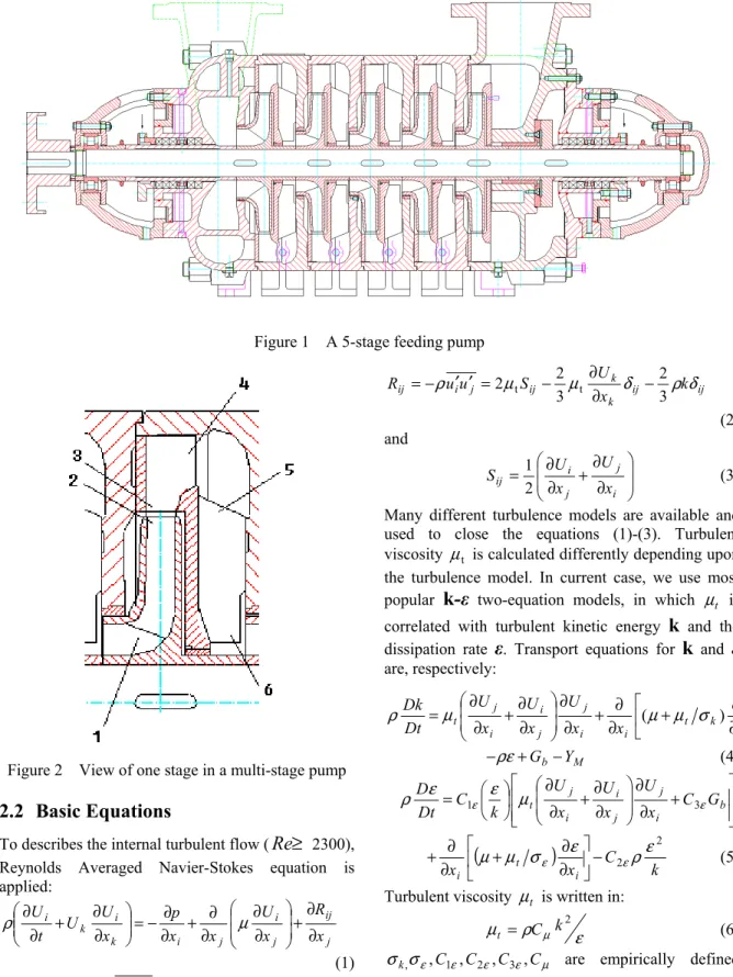
Figure 2 presents the view of one complete stage taken out the five-stage pump as shown in figure 1 and shows the flow route. Fluid starts from inlet of impeller (position 1), in turn passes by outlet of impeller (position 2), front vane inlet of diffuser (position 3), front vane outlet of diffuser (position 4), back vane inlet of diffuser (position 5), finally leaves the back vane outlet of diffuser (position 6) and enters next stage of the pump. Therefore, we can isolate an element from the multistage pump and form a computational domain that starts at position 1 and ends at position 6.
Figure 1 A 5-stage feeding pump
Figure 2 View of one stage in a multi-stage pump
2.2 Basic Equations
To describes the internal turbulent flow (
Re
≥
2300), Reynolds Averaged Navier-Stokes equation is applied: j ij j i j i k i k i x R x U x x p x U U t U ∂ ∂ + ∂ ∂ ∂ ∂ + ∂ ∂ − = ∂ ∂ + ∂ ∂ µ ρ (1) where,Rij = −ρui′u′j are the Reynolds Stresses,ij ij k k ij j i ij k x U S u u R ρ µ µ δ ρ δ 3 2 3 2 2 t t ∂ − ∂ − = ′ ′ − = (2) and ∂ ∂ + ∂ ∂ = i j j i ij x U x U S 2 1 (3) Many different turbulence models are available and used to close the equations (1)-(3). Turbulent viscosity µt is calculated differently depending upon the turbulence model. In current case, we use most popular
k-ε
two-equation models, in which µt is correlated with turbulent kinetic energyk
and the dissipation rateε
. Transport equations fork
andε
are, respectively: ∂ ∂ + ∂ ∂ + ∂ ∂ ∂ ∂ + ∂ ∂ = i k t i i j j i i j t x k x x U x U x U Dt Dk ) (µ µ σ µ ρ M b Y G − + −ρε (4) + ∂ ∂ ∂ ∂ + ∂ ∂ = b i j j i i j t C G x U x U x U k C Dt D ε ε ε µ ε ρ 1 3
(
)
k C x xi t i 2 2 ε ρ ε σ µ µ ε − ε ∂ ∂ + ∂ ∂ + (5)Turbulent viscosity µt is written in: ε ρ µ µ 2 k C t = (6) µ ε ε ε ε σ
σk, ,C1 ,C2 ,C3 ,C are empirically defined constants.
2.3 Generation of Zone, Mesh and
Reference Frame
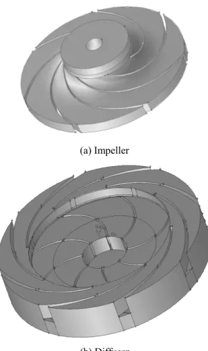
The pre-processor Gambit in FLUENT is performed to form the computational geometry zone and grids. Figure 3 shows the 3-D geometry creations of impeller (7 blades) and diffuser (8 vanes).
(a) Impeller
(b) Diffuser
Figure 3 Geometry creations of impeller and diffuser. For current complex pump geometries, tetrahedron mesh is used for grid generation. Figure 4 shows the appearance of tetrahedron grid generation of a stage combining impeller with diffuser. To the flows involving moving parts, multiple reference frames are provided in FLUENT. Here a moving reference frame (relative frame) is defined for impeller zone and a stationary reference frame (absolute frame) for the other zones.
Figure 4 Tetrahedron grid generations in a stage of pump
2.4 Setting of Boundary Conditions
The boundary condition at pump inlet (position 1 in figure 2) is prescribed by mass flow rate, which defines the velocity. Turbulent flow condition at pump entrance is given with intensity (5%) and hydraulic diameter. These two parameters are used to quantify turbulent kinetic energy, k and the dissipation rate, ε. Outflow boundary is set both at exit of domain (position 6) and the gap between impeller exit (position 2) and diffuser entrance (position 3), in which flow leakage takes place. This indicates that there are multiple exits in the domain. Flow rates at different exits are allocated according to leakage quantity. Wall boundaries are set on the surfaces adjacent to solid regions with no slip condition and roughness height of 0.40 mm. Standard wall functions are applied for near-wall treatment.
2.5 Operating Parameters and Material
Properties used in Calculation
Some flow operating parameters and fluid material properties used in current calculation are listed in Table 1, where the flow rate is the design point of the pump. Mass flow rate Q (kg/s) Impeller rotation speed N (rpm) Specific speed Ns Density ρ (kg/m3) Dynamic viscosity µ (kg/m-s) 75 1450 75 902 0.048 Table 1 Parameters of flow operating and material
3. N
UMERICALR
ESULTS ANDD
ISCUSSION3.1 Velocity Fields in Pump
Some representative computational results (steady state solutions) are shown in figures 5-9. Most information in these figures comes from the central positions in computational zones of impeller and diffuser. Figure 5 shows the whole 3-D view of path lines of fluid in the pump stage, which shows how the impeller imparts velocity to the fluid and the diffuser reduces the fluid velocity, thus increasing the pressure in the flow.
(a) Front side
(b) Back side
Figures 5 Path lines of fluid in pump stage. (a) front side; (b)
Figures 6 displays negative radial-velocity distribution inside the impeller and front-side of diffuser. This figure indicates the locations (in the vaneless radial gap between the impeller and the diffuser) where the reverse flow takes place. Even running at the designed operating point, the reverse flows exist in the pump, resulting in velocity field
asymmetry and instability with the iterations. This unsteady flow extend both upstream and downstream of the gap.
Figures 6 Contours of radial-direction velocity inside the impeller
Figures 8 gives relative flow velocity (i.e., related to the rotating reference frame as defined in figure 7) inside the impeller. Averagely, relative speed on pressure sides of blades is lower than that on suction sides, forming a considerable flow structure of jet/wake. Due to blockade of diffuser vane tip, some higher speed (yellow vectors in figure 7) comes out between impeller exit and diffuser vane tip. In this way, the location of such flow with extra speed changes with the rotation of the impeller, resulting in the variation of flow field in pump and instability of pump running.
Figures 8 Vectors of relative flow velocity inside the impeller
Figures 9 gives absolute velocity vectors inside the impeller and both sides of the diffuser. This figure displays that absolute velocity magnitude ranges within 30 m/s and the maximum fluid velocity in the flow is located around the tip of the impeller blades. The velocity direction of impeller is almost identical to that of diffuser vane. There is a considerable interference on velocity field at impeller exit due to the interaction between impeller blades and diffuser vanes. This is primarily due to the proximity of the vanes to the impeller blades and blade-wake interaction. In the back of the diffuser vane the velocity of the flow decreases while increasing the pressure (see figure 9-b).
(a) Front side
(b) Back side
Figures 9 Vectors of flow velocity inside the impeller and diffuser
3.2 Pressure Distribution in Pump
Figures 10 gives static pressure distribution of stage on front side and backside. Due to work of impeller, static pressure increases with the flow route in the impeller (see figure 10-a). In diffuser, static pressure keeps up while kinetic energy turns into potential energy and reaches maximum value at the end of front vane (see figure 10-a). Afterwards, pressure value decreases in some degree while flow turns its axial direction into radial one (see figure 10-b).
(b) Back side
Figures 10 Static pressure distribution inside the pump
3.3 Pump Head
To examine the validation of computation, the stage head of the pump can approximately be calculated using total pressure difference between outlet position 6 and inlet position 1,
dA g U g p A dA g U g p A H A A
∫
∫
+ − + = 1 2 1 6 2 6 2 1 2 1 ρ ρ(7) From equations (7), we get the predicted head value of H=38.3 m, which is close to the measured value H=40 m from the manufacturer. This implies the current turbulent simulation for a multistage pump is practical. On the other hand, equation (7) also enables us to connect 3-D flow field with pump performance.
4. C
ONCLUSIONA 3-D turbulent flow through an entire stage of a multistage centrifugal pump is numerically simulated by using the commercial software package, FLUENT, including flows in rotating impeller and stationary diffuser. It is found that the reverse flows exist near the impeller exit, resulting in flow field asymmetric and unstable. There is a considerable interference on velocity field at impeller exit due to the interaction between impeller blades and diffuser vanes. The current computation is verified by comparing predicted head with measured value.
R
EFERENCES[1] Yan, J and Smith, D G, CFD Simulation of 3-Dimensional Flow in Turbomachinery Applications, FLUENT Technical Notes, Presented at Turbomachinery Flow Prediction VIII, ERCOFTAC Workshop, March 2000. [2] Dai, J; Wu, Y; Cao, S, Study on Flows through
Centrifugal Pump Impeller by Turbulent Simulation, Journal of Hydrodynamics, 1997, 9(1) 11-23.
[3] Cao, S, Goulas, A, Yakinthis, K, et al., Numerical Simulation of Three-dimensional Turbulent Flow in a Centrifugal Pump Impeller. Proc. 3rd International Conf. Pump and Fans, Beijing, 1998, 411-418.
[4] Ren, J, Cao, S, Wu, Y, Numerical Simulation of Three-Dimensional Turbulent Flow in an Axial Flow Runner, Proc ASME/JSME Fluids Engineering Division Summer Meeting, 1999.