HAL Id: hal-00745217
https://hal.archives-ouvertes.fr/hal-00745217
Submitted on 2 Sep 2020
HAL is a multi-disciplinary open access
archive for the deposit and dissemination of
sci-entific research documents, whether they are
pub-lished or not. The documents may come from
teaching and research institutions in France or
abroad, or from public or private research centers.
L’archive ouverte pluridisciplinaire HAL, est
destinée au dépôt et à la diffusion de documents
scientifiques de niveau recherche, publiés ou non,
émanant des établissements d’enseignement et de
recherche français ou étrangers, des laboratoires
publics ou privés.
PICARD SOL mission, a ground-based facility for
long-term solar radius measurement
Mustapha Meftah, Abdanour Irbah, T. Corbard, F. Morand, Gérard Thuillier,
Alain Hauchecorne, R. Ikhlef, M. Rouze, Cédric Renaud, Djelloul Djafer, et al.
To cite this version:
Mustapha Meftah, Abdanour Irbah, T. Corbard, F. Morand, Gérard Thuillier, et al.. PICARD SOL
mission, a ground-based facility for long-term solar radius measurement. Proceedings SPIE 8446,
Ground-based and Airborne Instrumentation for Astronomy IV, Jul 2012, Amsterdam, Netherlands.
pp.844676, �10.1117/12.925712�. �hal-00745217�
PICARD SOL mission, a ground-based facility
for long-term solar radius measurement
M. Meftah
a,*, A. Irbah
a, T. Corbard
b, F. Morand
b, G. Thuillier
a, A. Hauchecorne
a, R. Ikhlef
bc,
M. Rouze
d, C. Renaud
b, D. Djafer
e, S. Abbaki
a, P. Assus
b, B. Chauvineau
b, E.M. Ciss´
e
a,
F. Dalaudier
a, E. D’Almeida
a, M. Fodil
c, F. Laclare
b, P. Lesueur
a, M. Lin
a, J.P. Marcovici
a,
and G. Poiet
a——
a
LATMOS, CNRS UMR 8190, Universit´
e Paris VI - Pierre et Marie Curie, Universit´
e de
Versailles Saint-Quentin-en-Yvelines, INSU, Guyancourt, France
b
Universit´
e Nice Sophia Antipolis, CNRS UMR 7293, OCA, Nice, France
cCRAAG, Observatoire d’Alger, Alger, Alg´
erie
d
CNES, 18 avenue Edouard Belin, 31401 Toulouse, France
e
Unit´
e de Recherche Appliqu´
ee en Energies Renouvelables, Gharda¨ıa, Alg´
erie
ABSTRACT
For the last thirty years, ground time series of the solar radius have shown different variations according to different instruments. The origin of these variations may be found in the observer, the instrument, the atmo-sphere and the Sun. These time series show inconsistencies and conflicting results, which likely originate from instrumental effects and/or atmospheric effects. A survey of the solar radius was initiated in 1975 by F. Laclare, at the Calern site of the Observatoire de la Cˆote d’Azur (OCA). PICARD is an investigation dedicated to the simultaneous measurements of the absolute total and spectral solar irradiance, the solar radius and solar shape, and to the Sun’s interior probing by the helioseismology method. The PICARD mission aims to the study of the origin of the solar variability and to the study of the relations between the Sun and the Earth’s climate by using modeling. These studies will be based on measurements carried out from orbit and from the ground. PICARD SOL is the ground segment of the PICARD mission to allow a comparison of the solar radius measured in space and on ground. PICARD SOL will enable to understand the influence of the atmosphere on the measured so-lar radius. The PICARD Sol instrumentation consists of: SODISM II, a replica of SODISM (SOso-lar Diameter Imager and Surface Mapper), a high resolution imaging telescope, and MISOLFA (Moniteur d’Images SOLaires Franco-Alg´erien), a seeing monitor. Additional instrumentation consists in a Sun photometer, which measures atmospheric aerosol properties, a pyranometer to measure the solar irradiance, a visible camera, and a weather station. PICARD SOL is operating since March 2011. First results from the PICARD SOL mission are briefly reported in this paper.
Keywords: Solar Astrometry, Turbulence, Solar radius, PICARD, SODISM, MISOLFA
1. INTRODUCTION
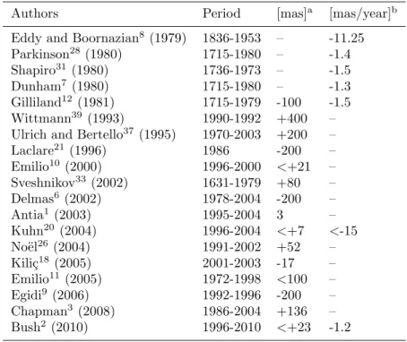
Solar particles and photons are the main sources affecting the terrestrial environment. Climate data allows us to analyze their frequencies. Among them, periodicities of 11-year, 22-year and about one century are likely related to solar activity opening the discussion of the influence of solar variability on the Earth’s climate. The solar radius measured during the Maunder minimum has experienced an increase in relation with solar activity of that period (Ribes et al.30). The relationship between the solar radius and the solar activity is the field of measurements and solar modeling. Ground-based measurements of the solar radius over three centuries are described by Ribes et al.30 (1987). Solar radius variations are discussed by Delache and Kroll5 (1994). A large spread of results (shown in Table 1) gathers solar radius variability from ground and space measurements.
* Corresponding author
Negative values indicate anti-correlated variations with solar activity and positive values indicate correlation. The solar radius variations with the solar activity will provide useful constraints to solar models. Published solar radius variability shows inconsistencies. Use of different methods of data processing to retrieve the solar radius, instruments operating at different wavelength and effect of the Earth’s atmosphere could explain the reported discrepancies (Thuillier et al.34 in 2005). The quantification of the solar atmosphere effects is the main aim of the PICARD SOL investigation by using complementary instrumentation, which will be presented here as well as the first results.
Table 1. List of solar radius variability - Solar cycle change (a) and secular change (b).
Authors Period [mas]a [mas/year]b
Eddy and Boornazian8 (1979) 1836-1953 – -11.25
Parkinson28(1980) 1715-1980 – -1.4
Shapiro31 (1980) 1736-1973 – -1.5
Dunham7 (1980) 1715-1980 – -1.3
Gilliland12(1981) 1715-1979 -100 -1.5
Wittmann39(1993) 1990-1992 +400 –
Ulrich and Bertello37(1995) 1970-2003 +200 –
Laclare21(1996) 1986 -200 – Emilio10(2000) 1996-2000 <+21 – Sveshnikov33 (2002) 1631-1979 +80 – Delmas6 (2002) 1978-2004 -200 – Antia1(2003) 1995-2004 3 – Kuhn20(2004) 1996-2004 <+7 <-15 No¨el26(2004) 1991-2002 +52 – Kili¸c18(2005) 2001-2003 -17 – Emilio11(2005) 1972-1998 <100 – Egidi9(2006) 1992-1996 -200 – Chapman3 (2008) 1986-2004 +136 – Bush2 (2010) 1996-2010 <+23 -1.2
2. DESCRIPTION OF THE PICARD MISSION
Jean PICARD,29a French astronomer of the Seventeenth century measured the solar radius, and determined
the Sun’s differential rotation velocity. This is why Jean Picard is the eponym astronomer of this mission. PICARD is a satellite dedicated to the simultaneous measurement of the solar radius, the solar shape, the total and spectral solar irradiance, and the solar interior dynamics. These measurements obtained throughout the mission will allow the study of their variations as a function of solar activity. The aims of the PICARD mission are to improve our knowledge of the functioning of our star through new observations.
One of the primary aims of the PICARD mission is to measure the solar radius and shape with an accuracy of a few milliarcseconds (mas) in orbit to avoid all atmospheric influence. The scientific aims of the PICARD mission are described in details by Thuillier et al.35 (2006). PICARD was launched on June 15, 2010 by a Dnepr-1 rocket close to the minimum of solar activity at the transition between solar cycle 23 and 24. The payload consists in two dual radiometers, Sun photometers, and a high resolution-imaging telescope named SODISM allowing us to measure the solar radius and shape, and to perform helioseismologic observations to probe the solar interior. SODISM has a ground-based replica placed at Calern (Observatoire de la Cˆote d’Azur) associated with several instruments used to characterize the atmosphere. This set of instruments will enable to understand the alteration of the solar limb shape induced by the Earth’s atmosphere. It will enable after the end of PICARD space mission to continue the measurements from the ground with the possibility of interpreting the solar radius variations.
3. CALERN SOLAR RADIUS MEASUREMENTS
The series of measurements of the solar radius at Calern Observatory spans about thirty five years. The solar radius survey was initiated in 1975 with the Solar Astrolabe. Measurements of the Sun radius were first achieved visually by the same observer using the Danjon’s astrolable. The DORAYSOL (D´efinition et Observation du RAYon SOLaire) instrument uses the same principle as the Solar Astrolable, but a CCD (Charge Coupled Device) is used for the acquisition, which makes it in principle independent of the observer. DORAYSOL is operating since 2000 (Morand et al.24 in 2010). Solar radius measurements performed at the Calern site have
shown long-time variations, which are still not explained. These variations show an anti-correlation with solar activity (Laclare et al.21 in 1996) in the period 1975-1994. These results have raised many questions and led
to the establishment of the international network R2S3 (R´eseau de Suivi au Sol du Rayon Solaire). Simulation of atmospheric effects on the solar radius measurements made at the Solar Astrolabe also showed the influence of seeing conditions and the importance of having a monitor encoding the quality of images acquired during the observations (Lakhal et al.22 in 1999). MISOLFA was designed for such measurements by providing the necessary information to interpret the solar images. It is founded on the observation of Angle-of-Arrival (AA) fluctuations and allows us to analyze atmospheric turbulence optical effects on measurements performed by SODISM II. MISOLFA gives estimations of the coherence parameters characterizing wave-fronts degraded by the atmospheric turbulence.
Only space observations will provide answers to the questions raised by the last decades of ground solar data. A long time survey of the Sun would be easier from the ground than from space (life of the satellite, space environment). Along with the PICARD satellite, SODISM II and MISOLFA will fill the gap at the Calern site.
4. DESCRIPTION OF THE PICARD SOL INSTRUMENTS
4.1 The SODISM II ground instrument
SODISM II (Figure 1) is an 11-cm diameter telescope associated with a 2048x2048 pixel CCD detector. The SODISM instrument is described in detail by Meftah et al.23 (2010). The instrument field of view and its angular
resolution are about 35 arcminutes and 1.06 arcseconds/pixel, respectively.
Figure 1. General view of SODISM II telescope. Figure 2. SODISM II optical system.
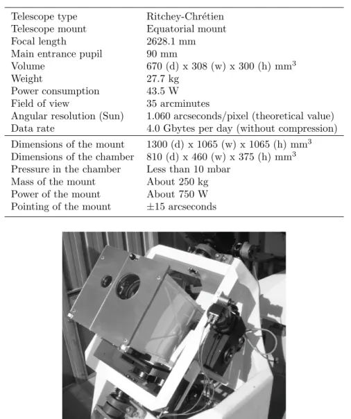
SODISM II observes the Sun in five wavelength domains by using interference filters. The SODISM II optical system (Figure 2) consists of a density filter (curved entrance window in silica back coated with a density filter), a primary mirror M1 in zerodur (radius of 804.61 mm, and conic of -1.01), a secondary mirror M2 in zerodur (radius of 186.07 mm, and conic of -1.9382), several interference filters, and a CCD. The instrument is operated by an electronic system named PGCU II (PICARD Gestion Charge Utile or PICARD Payload Management Unit, a replica of the space electronic unit). Table 2 summarizes the main characteristics of the SODISM II instrument. Solar images are recorded each minute. The Sun image is stabilized on the detector by the equatorial mount (better than±0.5 arcseconds during the exposure time). The instrument is placed in vacuum chamber closed by a glass window (Figure 3).
Table 2. SODISM II, and equatorial mount main characteristics.
Telescope type Ritchey-Chr´etien Telescope mount Equatorial mount Focal length 2628.1 mm Main entrance pupil 90 mm
Volume 670 (d) x 308 (w) x 300 (h) mm3
Weight 27.7 kg
Power consumption 43.5 W Field of view 35 arcminutes
Angular resolution (Sun) 1.060 arcseconds/pixel (theoretical value) Data rate 4.0 Gbytes per day (without compression) Dimensions of the mount 1300 (d) x 1065 (w) x 1065 (h) mm3
Dimensions of the chamber 810 (d) x 460 (w) x 375 (h) mm3
Pressure in the chamber Less than 10 mbar Mass of the mount About 250 kg Power of the mount About 750 W Pointing of the mount ±15 arcseconds
Figure 3. View of SODISM II equatorial mount.
4.1.1 The telescope thermal design
SODISM II requires a high level of thermo-mechanical stability to obtain the desired accuracy of solar radius measurements. A thermal control is implemented on the telescope and consists of i) an efficient thermal protection (Multi Layer Insulation or MLI) of the overall telescope, ii) a protection from solar illumination, iii) the implementation of a heating system monitored by several thermal sensors. Twenty heating lines are used to thermally stabilize the instrument at 20oC. The CCD (Charge Coupled Device) is also thermally regulated at -10oC±0.2oC to prevent any pixel size deformation and reduce its dark current, by using a Peltier element. The temperature of the interference filters is also regulated at 20oC ±1oC to ensure the stability of their spectral characteristics. The temperature of the entrance window is kept between 0 and 40oC in operating mode. Furthermore, the window is thermally insulated from the mechanical structure to avoid its deformations by thermal constraints. The SODISM II thermal control is based on a Proportional Integral (PI) regulation. The whole instrument is kept in vacuum chamber placed on the equatorial mount. The mechanical parts on the optical path are black anodized according to ESA-PSS 01/703.
4.1.2 Spectral domain of observation
Table 3 shows the main characteristics of the interference filters. All filters cleanliness complies with ESA-PSS-51. Anti-reflection coating is used to limit the reflection between the CCD and the back area of the filter.
Table 3. SODISM II interference filters characteristics.
Wavelengthλ [nm] Δλ [nm] Transmission Optical thickness Exposure time 393.37±0.1 0.7 6.2 to 10% 12.328 mm 1.70 s 535.7 (a)±0.05 0.5 29.5 to 35.1% 12.297 mm 1.30 s 535.7 (b)±0.05 0.5 26.3 to 32.8% 12.303 mm 8.90 s 607.1±0.1 0.7 33.5 to 42.8% 12.225 mm 1.28 s 782.2±0.2 1.6 29.7 to 37.6% 12.341 mm 1.43 s 1025.0±0.2 6.4 About 60% 12.080 mm 1.70 s
4.1.3 The Charge Coupled Device (CCD)
SODISM II uses an E2V CCD (No67). The E2V CCD 42-80 imaging sensor is a frame transfer matrix of 2048x4096 pixels, 13.5μm square pixel size, with back-thinned illuminated technology. Main characteristics of the CCD are given in Table 4. It works in UV light, and in the MPP (Multi Phase Pin) mode.
Table 4. SODISM II CCD characteristics.
Charge Transfer Efficiency Vertical 0.999999 Relation Electron/ADU (Analog to Digital Unit) e−/ADU 1.3
Maximum local Dark signal -40oC 0.42e−/pixel/s Maximum local Dark signal +20oC 6493e−/pixel/s Global PRNU (Photo Response Non Uniformity) At 400 nm 22.40%
At 550 nm 10.80% At 650 nm 8.30% At 750 nm 8.70% At 900 nm 9.50% Quantum Efficiency At 400 nm 43.00% At 500 nm 77.30% At 650 nm 86.90% At 800 nm 63.00% At 900 nm 33.20%
4.1.4 The density filter (entrance window) of the telescope
The silica (Suprasil) density filter (entrance window) protects the internal SODISM II optics, and limits the solar flux into the instrument (a diameter of 126 mm, a useful diameter of 114.3 mm, a center thickness of 8 mm, and a radius of curvature of 5 meters). It rejects 72.5% of the solar flux thus limiting solar flux inside the telescope. This blade has a total transmission of 5.8% for the wavelengths between 250 nm to 2500 nm.
4.1.5 The pointing mechanism
A pointing mechanism using three piezoelectric moves the primary mirror. The piezoelectric system is activated from information gathered by four photodiodes. Any unbalanced signal between pairs of detectors indicates a modification of the pointing. The main characteristics of the fine pointing are: a pointing accuracy of
±0.2 arcseconds, a stability of the summit of the primary mirror in Z of ±0.2 μm, and ability to have an image
offset of±60 arcseconds. The pointing mechanism is currently not activated. We use this system to correct the main optical, and radiometric defaults of the telescope, and for measuring the instrument flat-field.
4.2 The MISOLFA instrument
4.2.1 Introduction
Optical measurements being carried out on the ground, photons originating from a source such as a star or the Sun, experience absorption, scattering by the atmosphere molecules and aerosols, and turbulence. These effects generate a spread of the solar edge and affect the solar radius measurement. That is why the MISOLFA objective is to evaluate the atmosphere effects on the radius measurements. To interpret SODISM II radius measurements, MISOLFA determines the turbulence optical parameters (Fried parameterr0, the spatial coherence outer scale
L0, the isoplanetism domain θ0, the temporal characteristic of the wave front evolutionτ0 and the turbulence
vertical profileC2 n(h)).
The derivative of the solar limb allows an estimate of the impulse response of the entire atmosphere-telescope system. The spatio-temporal evolution of the impulse response gives access to parameters of coherence of the wavefront and location of the turbulent layers along the line of sight. The parameters for qualification and position of the turbulent layers in the atmosphere are estimated from the acquisition and analysis of image sequences from the Sun. The quality of the solar radius measurements can be assessed and the possibility of implementing methods of correcting optical effects induced by air turbulence studied either by post-processing or in real time (adaptive optics). The validity of the correction methods can be established by comparison with observations from space.
4.2.2 Principle
The MISOLFA design (Figure 4) is based on the statistical analyze of the entry angle fluctuations defined as the slope in each point of the wave front through the pupil. In the case of diurnal conditions, these fluctuations are shown by observations of the solar limb. There are two channels of measurements:
- A direct channel in which the Sun’s image is generated on a CCD camera with the suitable magnification. This channel enables the evaluation of the spatial coherence parameters of the wave front (Fried parameter, outer scale and isoplanetism domain) as well as the turbulence profiles,
- A second channel (pupil channel), which consists in forming the image of the pupil through a diaphragm placed on the solar limb, is used to evaluate the wave front temporal parameters using photo-electric detectors.
Figure 4. MISOLFA optical design. Figure 5. General view of MISOLFA seeing monitor.
4.2.3 The instrument
MISOLFA is a solar seeing monitor. It is described in detail by Irbah et al.15 (2010). Table 5 summarizes
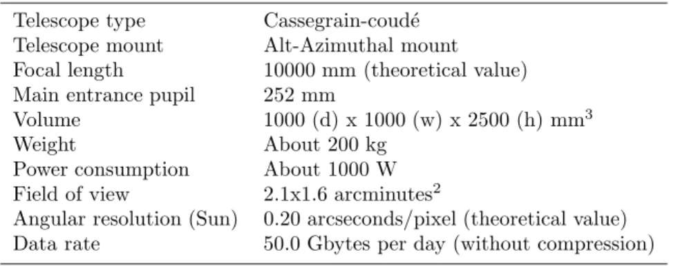
the main characteristics of MISOLFA (Figure 5). The MISOLFA telescope is pointed on the Sun and records thirty solar limbs each minute from which the atmosphere turbulence parameters are derived.
Table 5. MISOLFA main characteristics and mount.
Telescope type Cassegrain-coud´e Telescope mount Alt-Azimuthal mount Focal length 10000 mm (theoretical value) Main entrance pupil 252 mm
Volume 1000 (d) x 1000 (w) x 2500 (h) mm3
Weight About 200 kg
Power consumption About 1000 W Field of view 2.1x1.6 arcminutes2
Angular resolution (Sun) 0.20 arcseconds/pixel (theoretical value) Data rate 50.0 Gbytes per day (without compression)
4.2.4 Spectral domain of observation
Table 6 summarizes the main characteristics of the observed spectral domains interference filters. They are the same as for the SODISM II instrument.
Table 6. MISOLFA spectral domain of observation.
Wavelengthλ [nm] Δλ [nm] Exposure time 393 (Not yet integrated) 2.5 1 ms
535 2.5 1 ms
607 2.5 1 ms
782 (Not yet integrated) 2.5 1 ms 1025 (Not yet integrated) 2.5 1 ms
4.2.5 The CCD
MISOLFA uses a PCO PixelFly VGA CCD. The CCD imaging sensor is a frame transfer matrix of 640x480 pixels, 9.9μm pixel size. The system consists in an ultra compact camera head.
4.3 Additional instrumentation
The measurements achieved from ground are perturbed by different phenomena, which are time dependent. The Earth’s atmosphere contains aerosols such as water droplets, dust and ice crystals generating scattering to which turbulence effects are added. A dedicated instrumentation will allow detailed atmosphere characterization for long-term studies. A PICARD SOL Automatic Photometer (Photom`etre Automatique PICARD SOL, PAPS) will provide a quality index of pictures taken by SODISM II (effect of aerosols). A PICARD SOL pyranometer (Pyranom`etre PICARD SOL, PPS) is a radiometer that will measure the luminous flux received on a flat surface (measurement of the solar irradiance). A PICARD SOL visible wide-field Camera or Cam´era PICARD SOL (CPS) will be used.
4.3.1 The PICARD SOL photometer (PAPS)
The purpose of this solar photometer (CE 318 automatic Sun tracking photometer) is to measure Sun and Sky radiance in order to derive the total column water vapor (cm), ozone and aerosols properties using a combination of spectral filters and azimuth/zenith viewing controlled by a microprocessor. The photometer is composed of an optical head, an electronic box and a robot. The optical head has two channel systems: the sun collimator, without lens, and the sky collimator with lenses. The sun tracking is equipped with a 4-quadrant detector. The field of view of the instrument is 1.2 degree. PICARD SOL is on the AERONET (AErosol RObotic NETwork) program and is described in Holben et al.14 (1998). Aerosol Optical Depth (AOD) is a quantitative measure of the
extinction of solar radiation by aerosol scattering and absorption between the point of observation and the top of the atmosphere. It is a measure of the integrated columnar aerosol load and the single most important parameter for evaluating direct radiative forcing. AOD can be determined from the ground through measurements of the spectral transmission of solar radiation through the atmosphere using the PICARD SOL photometer. Table 7 summarizes the main characteristics of the interference filters. In order to perform solar radius measurements, chosen wavelengths are nearly the same as the SODISM II instrument.
Table 7. PICARD SOL Automatic Photometer (PAPS) interference filters characteristics.
Wavelengthsλ [nm] Δλ [nm] Exposure time 340, 380, 440, 500, 675, 870, and 1020 10 10 s
4.3.2 The PICARD SOL Pyranometer (PPS)
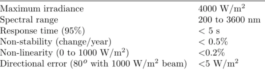
A pyranometer is used to measure the broadband solar irradiance including both the direct and scattered components within a 180 degrees field of view. This instrument (CMP 22 from Kipp & Zonen) is a scientific standard pyranometer with precision quartz domes that follows the Lambert’s law. Table 8 summarizes the main characteristics of this pyranometer.
Table 8. PICARD SOL Pyranometer (PPS) main characteristics.
Maximum irradiance 4000 W/m2
Spectral range 200 to 3600 nm
Response time (95%) < 5 s
Non-stability (change/year) < 0.5% Non-linearity (0 to 1000 W/m2) <0.2%
Directional error (80o with 1000 W/m2 beam) <5 W/m2
4.3.3 The PICARD SOL visible wide-field Camera (CPS)
The SBIG AllSky-340 Color (Santa Barbara Instrument Group) is a color wide field camera for monitoring the weather conditions and in particular the presence of cirrus. Its field of view is slightly greater than 180 degrees in the horizontal direction.
5. SODISM II CALIBRATIONS
5.1 Dark current and bias
Each CCD pixel will have a certain minimum of electrical charge even if the exposure is of zero duration. This means that pixel values will always be greater than zero even for the shortest exposures. This is called bias. Each CCD pixel will accumulate additional charge during the exposure even if there is no light falling on it. This means that pixel values will be higher than they should be by an amount that depends on the length of the exposure. This is dark current of the CCD, and we need to correct the image of the Sun. Dark current images may be performed every day, and with an exposure time of one second.
5.2 Flat-field calibration
Flat-field corrections are important for achieving as precise as possible Sun radius measurements as each camera pixel has a slightly different sensitivity to light. A major issue with CCD detectors is that although the linearity of any pixel over a wide dynamic range is excellent, the gain and dark current variation among different pixels can be quite large. Flat-field measurements must be made with the telescope. We will use a method developed by Kuhn et al.19 (1991), and is based on the displacement of multiple images with the same luminous
flux (Sun image). The displacement of the image can be achieved in two ways: by moving the telescope’s primary mirror (see above) or by using the equatorial mount of SODISM II. This operation is performed each three months and for each wavelength.
5.3 Angular resolution calibration
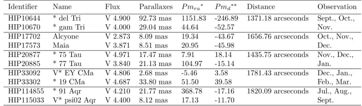
SODISM II aims to the determination of the absolute value of the solar radius with an uncertainty of the order of 100 mas. The theoretical value of the angular resolution of the telescope is 1.060 arcseconds/pixel. We will use the positions of stars to determine the angular resolution of SODISM II. The stars are selected according to their brightness, angular distances close to 32 arcminutes, and their elevation above the horizon. The highest acceptable magnitude is 5. The declination angle must be greater than -20 arcdegrees given the limitation of the equatorial mount. Five pairs of stars (Table 9) were selected (Centre de Donn´ees Astronomiques de Strasbourg, SIMBAD4, rel. 1.182) at different periods of the year. Table 9 provides additional information with the validation of the new Hipparcos reduction (Van Leeuwen38 in 2007). Processing data includes several corrections: proper
motion of the star, parallax depending on the position of Earth around the Sun, and aberration.
Table 9. Pairs of stars, and stars distance (J2000 from SIMBAD).
Identifier Name Flux Parallaxes P mra∗ P md∗∗ Distance Observation HIP10644 * del Tri V 4.900 92.73 mas 1151.83 -246.89 1371.18 arcseconds Sept., Oct., HIP10670 * gam Tri V 4.000 29.04 mas 44.64 -52.57 Nov. HIP17702 Alcyone V 2.873 8.09 mas 19.34 -43.67 1656.76 arcseconds Oct., Nov.,
HIP17573 Maia V 3.871 8.51 mas 20.95 -45.98 Dec.
HIP20877 * 75 Tau V 4.971 17.47 mas 7.91 18.14 1435.75 arcseconds Nov., Dec., HIP20885 * 77 Tau V 3.840 21.13 mas 104.97 -15.14 Jan. HIP33092 V* EY CMa V 4.806 2.68 mas -5.46 3.58 1781.43 arcseconds Dec., Jan., HIP33302 * 19 CMa V 4.687 33.80 mas 51.50 39.58 Feb., Mar. HIP114855 * 91 Aqr V 4.210 21.77 mas 368.78 -17.16 1820.09 arcseconds Jul., Aug., HIP115033 V* psi02 Aqr V 4.400 8.12 mas 17.13 -11.70 Sept.
∗ Proper motion (right ascension): P m
ra (mas/year),∗∗Proper motion (declination): P md (mas/year)
We run two series of measurements to determine the angular resolution of SODISM II (August 2011, and March 2012). The theoretical value of the angular resolution of the telescope is 1.055 arcseconds/pixel (without diopter). A Ritchey-Chr´etien telescope is a specialized Cassegrain telescope that has a hyperbolic primary mirror, and a hyperbolic secondary mirror allowing to eliminate coma. For stellar measurements, there is no interferential filter. The optical combination is not nominal (presence of coma). The measurements result in values smaller than the expected values (Table 10). The two series provide slightly different values. The necessary corrections of atmospheric refraction (right ascension, and declination of the pair of stars) have not been applied. We note that a greater number of measurements are available to improve the uncertainty, which is presently of the order of 90 mas affecting the measurement of the stars angular distances.
Table 10. SODISM II, angular resolution measurements f(star).
Identifier Name Distance, f(star) N Observation HIP114855 * 91 Aqr 1723.19 pixels±0.35 9 10 August 2011 HIP115033 V* psi02 Aqr f(star) = 1.0539±0.0002 22H43
HIP33092 V* EY CMa 1692.02 pixels±0.19 13 14 March 2012 HIP33302 * 19 CMa f(star) = 1.0533±0.0001 19H39
6. PRELIMINARY RESULTS AND DISCUSSION
SODISM II records full solar images at several wavelengths since March 2011 for solar radius measurement. Simulations and methods developed to measure the solar radius are described by Irbah et al.16 (2010). The solar
radius is defined as the position of the inflection point of the Limb Darkening Function (LDF). From ground, the solar radius is obtained at several solar zenith angle. The solar radius is usually measured by determining the inflection point of the solar limb. This point is located at a position where the signal-to-noise ratio is rather low, which requires an appropriate filtering technique to eliminate the noise and an interpolation, which preserves its position. Most of the measurements of the solar limb profile were obtained from the ground. Different effects can introduce a bias in the solar radius measurement. Major effects are: refraction, atmospheric turbulence, instrumental effects (PSF, thermo-optical effects, ...). Other effects have an impact, such as absorption and scattering of the solar light by aerosols, and the spectral domain of observation must be taken into account. Corrections can be applied for the determination of the solar radius, however currently only with limited precision. The angular resolution and distortion of the telescope must be known to high accuracy.
The auxiliary data relevant of the solar radius measurements are: turbulence measured by MISOLFA, aerosols measured by the filters photometer, cloudiness measured by the pyranometer and cloudiness detected by the camera. The seeing monitor MISOLFA, and the solar diameter imager SODISM II observe the Sun together since March 2011. Additional instrumentation is in operation since July 2011.
6.1 MISOLFA preliminary results
Data were recorded with MISOLFA using its two observation channels (see relevant paragraph). Data incoming from the image plane observation channel consists in series of image of about 2400 samples recorded at a rate of 30 images per seconds. Figure 6 shows an image of the Sun recorded on August 11, 2011. Their size is about 96 by 128 arcseconds. Each CCD pixel line of the direct and reflected limb images is in a direction parallel to the horizon. Results from the MISOLFA instrument are described in detail by Irbah al.17 (2011).
The Fried parameter measures the optical quality of the atmosphere.
Figure 6. A solar image obtained with MISOLFA.
5 10 15 20 25 30 0 0.05 0.1 0.15 0.2 0.25 [arcsec] arbitrary unit 930 940 950 960 970 980 0 0.1 0.2 0.3 0.4 0.5 0.6 [arcsec]
intensity [arbitrary unit]
ro = 1 cm
ro = 3 cm
ro = 5 cm
solar limb at the focal plane without atmospheric effect ro = 7 cm ro = 5 cm ro = 3 cm ro = 2 cm ro = 1 cm (a) (b)
Figure 7. Limb profile (b), and its derivative (a) vsr0.
The final value of Fried parameterr0 obtained when considering the duration of all the series of images (74
seconds) recorded on August 11, 2011, is of the same order as the one found when fitting the experimental structure function with the theoretical model. The result is shown in Figure 8 (an index corresponds to 2 seconds). As expected, we find close values forr0 with either direct or reflected images. There is no spatial
consistency (Irbah al.17 in 2011) and turbulence is rapidly evolving. When the atmospheric turbulence increases
(r0about 0), the solar radius decreases (shown in Figure 7). During one day, the radius may vary by 1 arcsecond
0 5 10 15 20 25 30 35 40 0.5 1 1.5 2 2.5 3 3.5 4 4.5 index r0 (cm) 0 5 10 15 20 25 30 35 40 1 1.5 2 2.5 3 3.5 4 4.5 index r0 (cm)
Figure 8.r0 estimated from reflected (left), and direct (right) solar image (11 August 2011 09H55).
6.2 PAPS preliminary results
This instrument allows derivation of ozone, aerosols and water vapor. The results are shown in Figure 9. We note the relationship between water vapor and aerosols.
May20110 Jun2011 Jul2011 Aug2011 Sep2011 Oct2011 Nov2011 Dec2011 Jan2012 Feb2012 Mar2012 Apr2012 May2012 0.5
1 1.5 2
Water Vapor [cm]
May2011 Jun2011 Jul2011 Aug2011 Sep2011 Oct2011 Nov2011 Dec2011 Jan2012 Feb2012 Mar2012 Apr2012 May2012 10−2
10−1
100
Aerosol Optical Thickness
AOT 1020nm AOT 870nm AOT 675nm AOT 500nm AOT 440nm AOT 380nm AOT 340nm
Figure 9. Aerosol optical data, and water vapor - Calern site.
6.3 PPS preliminary results
The PICARD SOL pyranometer has been measuring the solar radiation flux density (in watts per square meter) since July 2011. A detailed analysis must be conducted to study the effect of solar radiation variation on the solar radius measurement made by SODISM II.
6.4 SODISM II preliminary results
SODISM II recorded its first light on 18 March 2011 at 11H16 UTC (Universal Time Coordinated). The first operations were dedicated to the adjustment of the pointing of the equatorial mount. In a second step, we developed a system that allowed us to automatically record images. Several solar images at different wave-lengths have been recorded since 6 May 2011. Figure 10 shows simultaneous images from SODISM II (left) and Helioseismic and Magnetic Imager HMI (right). The image of the Sun (left) has been obtained on April 20, 2012 at 535.7 nm (Sun position angle P=-25.56o, heliographic latitude B0=-5.13o, parallactic angle p=10.4o), with dark current correction, however without flat-field correction. The blue line is used to display the local horizon. A grid of helio latitudes and longitudes have been overlaid on both images taking into account P and B0 angles. From looking at the location of sunspots on these grids, we can see that SODISM II alignment is very good.
Figure 10. Image of the Sun taken by SODISM II (left) and HMI (right) at the same date.
Solar limb profiles measured by SODISM II, and its derivative (limb width) at 535.7 nm from 0o(horizontal axis of the image) to 360o (counterclockwise) are shown in Figure 11. Measurement Number corresponds to an image taken by SODISM II at a given time. There is a dependency between the solar limb profile, and the angular sector of the image. The dependence with the sector is likely due to SODISM II optical distortion. The limb shape spreads over several pixels due to the optics and atmospheric turbulence. Several limbs shape models are available either essentially theoretical, or empirical. Some models are empirically constructed (Neckel252005
or HM98 described by Hestroffer and Magnan13), and others use theoretical studies (e.g. COSI described by Shapiro et al.32) or 3D MHD (MagnetoHydroDynamics) numerical simulations (Nordlund272009). Some models properties are compared by Thuillier et al.36 (2011). At the scale of 50 mas, they mostly agree.
The most typical definition of solar radius is based on the determination of the position of the inflection point of the solar limb profile. The inflection point is defined as the maximum of the LDF derivative squared in polar coordinate system (image of the Sun). A special filtering is applied to avoid bad CCD lines (shown in Figure 10). After computing the inflection point position contour, the best fit to an ellipse (using the least squares method) is achieved providing an estimation of the average value of the solar radius. Data were not corrected for refraction, nor turbulence, which may explain most of the low values of the measurements. An evolution of the solar radius measurement is shown in Figure 12 as a function of time for different wavelengths. They behave similarly, however providing different solar radius.
Jul2011 Oct2011 Jan2012 Apr2012 903 903.5 904 904.5 905 Semi−Diameter [pixels] 393.37 nm
Jul2011 Oct2011 Jan2012 Apr2012 903 903.5 904 904.5 905 Semi−Diameter [pixels] 535.7 nm (a) 535.7 nm (b)
Jul2011 Oct2011 Jan2012 Apr2012 903 903.5 904 904.5 905 Semi−Diameter [pixels] 607.1 nm
Jul2011 Oct2011 Jan2012 Apr2012 903 903.5 904 904.5 905 Semi−Diameter [pixels] 782.2 nm 1025.0 nm
Figure 12. SODISM II solar Semi-Diameter measurement (without correction, and at one A.U.).
Figure 13 displays the relationship between the solar radius and the zenith distance. Effects of atmospheric refraction on astronomical measurements are calculated for Calern (N 43o44’56”, E 6o55’37”, 1270 m) with temperature and pressure, which are measured by the local weather station. A typical refraction effect is shown in Figure 14. The refraction effect may explain most of the low values of the measurements (up to 1.5 pixels).
0 10 20 30 40 50 60 70 80 90 903 903.5 904 904.5 905 Zenith distance [°] Semi−Diameter [pixels] 393.37 nm 0 10 20 30 40 50 60 70 80 90 903 903.5 904 904.5 905 Zenith distance [°] Semi−Diameter [pixels] 535.7 nm (a) 535.7 nm (b) 0 10 20 30 40 50 60 70 80 90 903 903.5 904 904.5 905 Zenith distance [°] Semi−Diameter [pixels] 607.1 nm 0 10 20 30 40 50 60 70 80 90 903 903.5 904 904.5 905 Zenith distance [°] Semi−Diameter [pixels] 782.2 nm 1025.0 nm
15 20 25 30 35 40 45 50 55 60 65 70 −1.6 −1.4 −1.2 −1 −0.8 −0.6 −0.4 −0.2 0 Zenith distance [°]
Refraction effect on Semi−Diameter [Arc−seconds]
Figure 14. SODISM II refraction effect - 535.7 nm (b).
On the image (Figure 10, left image), the direction parallel to the local horizon (given by the parallactic angle) is the less affected by refraction. With a telescope on an equatorial mounting (SODISM II case), the top and bottom points on the solar disk are on the celestial meridian (great circle going through pole). This means that the north and south cardinal points are always at the top or bottom of the solar disk and the east and west cardinal point are to the left or right. The parallactic angle has a positive value if the Sun is to the west of the meridian, and negative to the east. It is necessary to correct the image (dark current, and flat-field), and to have the knowledge of the distortion of the image taken by SODISM II.
Figure 12 shows that the two 535.7 nm filters provide similar mean results, however with different level of noise. The measurement of the solar radius achieved through the two filters at 535.7 nm (Figure 13) confirm that there is less measurements dispersion for exposure time the longest (1.7 s for 535.7 nm (a), and 8.9 s for 535.7 nm (b)). Furthermore, Figure 12 and 13 display results at other wavelengths providing similar behavior as a function of time and solar zenith angle. Indeed, we perform measurements with one identical wavelength: SODISM II solar radius measurement (535.7 nm), corrected from refraction (Danjon4) is shown in the Figure 15. Mean
semi-diameter (solar radius) of 904.0 pixels (withσ=0.19 pixels) is deduced from more than 2,000 measurements.
May2011 Jun2011 Jul2011 Aug2011 Sep2011 Oct2011 Nov2011 Dec2011 Jan2012 Feb2012 Mar2012 Apr2012 May2012 902 902.5 903 903.5 904 904.5 905 Semi−Diameter [pixels] 535.7 nm (b)
535.7 nm (b) corrected from refraction (extrapolation with Zenith distance z=0°) y mean
y std
7. CONCLUSION
PICARD SOL is the ground segment of the PICARD mission. The seeing monitor MISOLFA, and the solar diameter imager SODISM II have been observing the Sun together since March 2011. MISOLFA is a high cadence solar limb imager allowing us to measure the spatio-temporal parameters of the local turbulence. SODISM is a multi-wavelength full disk solar imager specially designed for metrological measurements. Ad-ditional instrumentation (photometer and pyranometer) are in operation since July 2011. The PICARD SOL photometer provides a quality index of pictures taken by SODISM II (aerosol optical depth). The PICARD SOL pyranometer measures the luminous flux received, and provides another quality index for SODISM II mea-surements. The PICARD SOL mission is a ground-based facility for long-term solar radius measurement. The quality of the solar radius measurements can be assessed as well as the possibility of implementing methods of correcting refraction, atmospheric turbulence, scattering of the solar light by aerosols, instrumental effects (PSF, and thermo-optical effects, degradation), and spectral domain of observation. The validity of the correction methods can be established by comparison with observations from space (PICARD satellite, ...).
PICARD SOL preliminary results are very promising and the first solar radius measurements are in good agree-ment with those obtained on the same site with other instruagree-ments. But there is still much work needed to automate operations. Observers are doing an outstanding work with instruments that are not completely fi-nalized (rapid degradation of MISOLFA window treatment, bad lines on SODISM II CCD, ...). Three major activities must be carried out: basic CCD and image calibrations (dark current, flat-field, PSF, thermo-optical effects and image distortion), evaluation and correction of atmospheric effects on the SODISM II measurements (refraction, atmospheric turbulence, small angle aerosol scattering), and the calibration of SODISM II absolute angular resolution. Getting precise CCD flat-fields from ground observations has specific requirements that must be addressed and, in the future, we plan a further reduction of the CCD temperature down to about -20oC and changing the CCD in order to reduce the current number of bad lines. MISOLFA is designed to provide measure-ments of all spatio-temporal parameters of the local turbulence at the time of SODISM II image records allowing us (using both measurements and a turbulence model) to construct, for each image, an instrument/atmosphere equivalent PSF in the direction slightly affected by refraction (given by the parallactic angle). The PICARD SOL photometer provides a continuous aerosol optical depth record that can be used as an image quality index and to assess the possible effects of small angle scattering on radius measurements. Finally SODISM II must be able to monitor not only the relative short term variations of the solar radius, if any, but also the long term variations. For this an absolute calibration of the angular resolution is fundamental. This can be done by stellar calibration using pairs of stars, and using Hipparcos (or the upcoming GAIA) catalogs corrected for proper motions and refraction.
We plan to include PICARD SOL data in a virtual observatory. A Virtual Observatory (VO-SCAT, http://bdap. ipsl.fr/voscat/) dedicated to the Sun-Earth atmosphere relation has been developed in the frame of the Inter-national Virtual Observatory Alliance (IVOA, http://www.ivoa.net/), and the InterInter-national Planetary Data Al-liance (IPDA, http://planetarydata.org/). We plan to include PICARD SOL data also in BASS 2000 (http://bass 2000.bagn.obs-mip.fr/). PICARD SOL is on the AERONET (AErosol RObotic NETwork) program.
ACKNOWLEDGMENTS
This project is a collaboration between LATMOS (IPSL), LAGRANGE (OCA), and CRAAG (Algiers) and is supported by the French space agency (CNES) as part of the PICARD mission, the CNRS, and the French Foreign Affair Ministry in the framework of the scientific cooperation contract TASSILI 07MDU713 between France and Algeria. The PICARD SOL mission was developed by CNRS-LATMOS, and by OCA. We thank CNES (Centre National d’Etudes Spatiales), CNRS (Centre National de la Recherche Scientifique), Laboratoire d’Optique Atmosph´erique (University of Lille 1), and LESIA (Laboratoire d’Etudes Spatiales et d’Instrumentation en Astrophysique) for their support as well as all the participants who have devoted their expertise to this project. We wish to express our gratitude to all CNES and CNRS members who participated in the preparation of this mission. The PICARD SOL development has been made possible by funding from the CNES and the CNRS. We would like to acknowledge the whole PICARD SOL project team who have done remarkable work towards a successful mission. We thank the PICARD team and their staff for establishing, and maintaining the Calern site used in this investigation. We acknowledge the use of the SDO/HMI observations for this study. The SDO/HMI images are provided by the Joint Science Operations Center (JSOC).
REFERENCES
[1] Antia, H. M., Does the Sun Shrink with Increasing Magnetic Activity?, APJ , Volume 590, Issue 1, pp. 567-572, (2003).
[2] R.I. Bush, M. Emilio, and J.R. Kuhn, On the constancy of the solar radius III, The astrophysical journal, 716, 1381-1385, (2010). [3] Chapman, G. A.; Dobias, J. J.; Walton, S. R., On the Variability of the Apparent Solar Radius, The Astrophysical Journal, Volume 681,
Issue 2, pp. 1698-1702, (2008).
[4] Danjon A., Astronomie g´en´erale, Astronomie sph´erique et ´el´ements de m´ecanique c´eleste, J. & R. Sennac, 1952 ; seconde ´edition, revue et corrig´ee, (1959).
[5] Delache P, Kroll R. J., Panel discussion on Solar diameter variations, The Solar Engine and its Influence on Terrestrial Atmosphere and Climate, Proceedings of the NATO Advanced Research Workshop held 25-29 October, 1993 in Paris, France. Edited by Elizabeth Nesme-Ribes. Berlin Heidelberg: Springer Verlag, 1994., p.193, (1994).
[6] Delmas, C., and Laclare, F., Short versus long time series: example of the solar diameter, Solar Physics, 209, 391-396, (2002). [7] Dunham, J. B., Dunham, D. W., and Fiala, A. D., Solar Radius Variations Determined from Observations of Four Eclipses, Bulletin of
the American Astronomical Society, Vol. 12, p. 832, (1980).
[8] Eddy, J.A. and A.A. Boornazian, Secular increase in the solar diameter, 1836-1953, Bulletin of the American Astronomical Society, 11:437, (1979).
[9] Egidi, R., Caccin, B., Sofia, S., Heaps, W., Hoegy, W., and Twigg, L., High Precision Measurements of the Solar Diameter and Oblateness by the Solar Disk Sextant Experiment, Solar Physics, 235, 410-432, (2006).
[10] Emilio, M.; Kuhn, J. R.; Bush, R. I.; Scherrer, P., On the Constancy of the Solar Diameter, The Astrophysical Journal, Volume 543, Issue 2, pp. 1007-1010, (2000).
[11] Emilio, M. and Leister, N. V., Solar diameter measurements at So Paulo Observatory, Monthly Notices of the Royal Astronomical Society, Volume 361, Issue 3, pp. 1005-1011, (2005).
[12] Gilliland, R.L., Solar radius variations over the past 264 years, Astrophysical Journal, 248:1144-1155, (1981).
[13] Hestroffer D. and Magnan C., Wavelength dependency of the Solar limb darkening, Astronomy and Astrophysics, Volume 333, 338-342, (1998).
[14] Holben B.N., T.F. Eck, I. Slutsker, D. Tanr´e, J.P. Buis, A. Setzer, E. Vermote, J.A. Reagan, Y. Kaufman, T. Nakajima, F. Lavenu, I. Jankowiak, and A. Smirnov, AERONET - A federated instrument network and data archive for aerosol characterization, Rem. Sens. Environ., 66, 1-16, (1998).
[15] A. Irbah , T. Corbard, P. Assus, J. Borgnino, C. Dufour, R. Ikhlef, F. Martin, M. Meftah, F. Morand, C. Renaud and E. Simon, The solar seeing monitor MISOLFA: presentation and first results, ed. SPIE, Volume 7735, pp. 77356F-77356F-9, (2010 a).
[16] Irbah A., Dufour C., Meftah M., Meissonnier M., Thuillier G., Assus P., Corbard T., Pradels G., Solar radius measurements with the SODISM instrument : methods and algorithm developments for the PICARD Payload Data Center, Astronomische Nachrichten AN 331, 9-10 (2010) 59, (2010 b).
[17] Irbah A., Meftah M., Corbard T., Ikhlef R., Morand F., Assus P., Fodil M., Lin M., Ducourt E., Lesueur P. et al, Ground-based solar astrometric measurements during the PICARD mission, SPIE, Volume 8178, (2011).
[18] Kili¸c, H.; Golbasi, O.; Chollet, F., Measurements of the Solar Radius in Antalya between 2001 2003, Solar Physics, Volume 229, Issue 1, pp. 5-12, (2005).
[19] Kuhn, J. R., Lin, H. and Loranz, D., Gain calibrating nonuniform image-array data using only the image data, PASP, 103, 1097, (1991). [20] Kuhn, J.R., Bush, R.I., Emilio, M. and Scherrer, P., On the constancy of the solar diameter II, The astrophysical journal, 613, 1241-1252,
(2004).
[21] Laclare F., Delmas C., Coin J. P., Irbah A., Measurements and Variations of the Solar Diameter, Solar Physics, Volume 166, Issue 2, pp. 211-229, (1996).
[22] L. Lakhal, A. Irbah, M. Bouzaria, J. Borgnino, F. Laclare, Ch. Delmas, Error due to atmospheric turbulence effects on solar diameter measurements performed with an astrolabe, Astron. Astrophys. Suppl. Ser. 138, 155-162, (1999).
[23] M. Meftah, M. Meissonnier, A. Irbah, S. Abbaki, P. Assus, E. Bertran, J.P. Dubois, E. Ducourt, C. Dufour, J.P. Marcovici, G. Poiet, A.J. Vieau, G. Thuillier, The Space instrument SODISM and the Ground instrument SODISM II, ed. SPIE, Volume 7731, pp. 773145-1 773145-12, (2010).
[24] F. Morand, Ch. Delmas, T. Corbard, B. Chauvineau, A. Irbah, M. Fodil, F. Laclare, Solar radius measurements with the DORAYSOL instrument (1996-2006) at the Calern site of the observatoire de la Cte d’Azur, C.R. Physique, 11, 660-673, (2010).
[25] Neckel Heinz, Analytical Reference Functions F(λ) for the Sun’s Limb Darkening and Its Absolute Continuum Intensities (λλ 300 to 1100 nm), Solar Physics, Volume 229, Issue 1, pp.13-33 (2005).
[26] No¨el F., Solar cycle dependence of the apparent radius of the Sun, Astronomy and Astrophysics, v. 413, pp. 725-732, (2004). [27] Nordlund ˚Ake, Stein Robert F., Asplund Martin, Solar Surface Convection, Living Reviews in Solar Physics, vol. 6, no. 2, (2009). [28] Parkinson, J.H., L.V. Morrison, and F.R. Stephenson, The constancy of the solar diameter over the past 250 years, Nature, 288:548-551,
(1980).
[29] Picard, J., Arch. Obs. Paris, D1, 14-16, (1666-1682).
[30] Ribes, E., Beardsley, B., Brown, T. M., Delache, Ph., Laclare, F., & Leister, N. V., The variability of the solar diameter, The sun in time (A92-46664 19-92). Tucson, AZ, University of Arizona Press, 1991, p. 59-97, (1991).
[31] Shapiro I.I., Is the sun shrinking?, Science, 208:51-53, (1980).
[32] Shapiro A.I., Schmutz W., Schoell M., Haberreiter M., Rozanov E., NLTE solar irradiance modeling with the COSI code, Astronomy and Astrophysics, Volume 517, id.A48 (A&A Homepage), (2010).
[33] Sveshnikov, M.L., Solar radius variation from transits of Mercury across the solar disk, Astronomy Letters, 28, 115-120, (2002). [34] Thuillier G., Sofia S., Margit Haberreiter M., Past, present and future measurements of the solar diameter, Adv. Sp. Res. Vol. 35, Issue
3, 329-340, (2005).
[35] G. Thuillier, S. Dewitte, W. Schmutz and the PICARD team, Simultaneous Measurements of the Total Solar Irradiance and Solar Diameter by the PICARD mission, Adv. Space Res., 1792-1806, (2006).
[36] G. Thuillier, J. Claudel, D. Djafer, M. Haberreiter, N. Mein, S.M.L. Melo, W. Schmutz, A. Shapiro, C.I. Short, S. Sofia, The Shape of the Solar Limb: Models and Observations, Solar Physics, 268: 125149, (2011).
[37] Ulrich and Bertello, Solar-cycle dependence of the Sun’s apparent radius in the neutral iron spectral line at 525 nm, Nature, Volume 377, Issue 6546, pp. 214-215, (1995).
[38] Van Leeuwen, F., Validation of the new Hipparcos reduction, Astronomy and Astrophysics, Volume 474, Issue 2, pp.653-664, (2007). [39] Wittmann, Axel D.; Alge, Edoardo; Bianda, Michele, Detection of a significant change in the solar diameter, Solar Physics, 145, 205,