Analyzing Performance and Usability of
Broadcast-Based Inter-Core Communication
(ATAC) on Manycore Architecture
by
Seo Jin Park
Submitted to the Department of Electrical Engineering and Computer
Science
in partial fulfillment of the requirements for the degree of
Master of Engineering in Electrical Engineering and Computer Science
at the
MASSACHUSETTS INSTITUTE OF TECHNOLOGY
June 2013
c
Massachusetts Institute of Technology 2013. All rights reserved.
Author . . . .
Department of Electrical Engineering and Computer Science
May 23, 2013
Certified by . . . .
Armando Solar-Lezama
Associate Professor
Thesis Supervisor
Accepted by . . . .
Dennis M. Freeman
Chairman, Masters of Engineering Thesis Committee
Analyzing Performance and Usability of Broadcast-Based
Inter-Core Communication (ATAC) on Manycore
Architecture
by
Seo Jin Park
Submitted to the Department of Electrical Engineering and Computer Science on May 23, 2013, in partial fulfillment of the
requirements for the degree of
Master of Engineering in Electrical Engineering and Computer Science
Abstract
In this thesis, I analyze the performance and usability benefits of broadcast-based inter-core communication on manycore architecture. The problem of high communi-cation cost on manycore architecture was tackled by a new architecture which allows efficient broadcasting by leveraging an on-chip optical network. I designed the new architecture and API for the new broadcasting feature and implemented them on a multicore simulator called Graphite. I also re-implemented common parallel APIs (barrier and work-stealing) which benefit from the cheap broadcasting and showed their ease of use and superior performance versus existing parallel programming li-braries through conducting famous benchmarks on the Graphite simulator.
Thesis Supervisor: Armando Solar-Lezama Title: Associate Professor
Acknowledgments
Foremost, I would like to thank my adviser Armando Solar-Lezama for his tireless support, guidance, and encouragement. I was not very experienced in computer architecture area before this project, but his continuous support and guidance made me successful and interested throughout the process of research in this area, finally leading me to continue study in this area for my Ph.D program.
Whenever I struggled with Graphite, George Kurian helped me solve the issues from small bugs to the big pictures on modeling. His guidance was especially helpful for me not to be lost in the middle of huge Graphite code base.
Lastly, I would like to thank my colleagues James Psota and Nick Pellegrino for being great teammates.
Contents
1 Introduction 13
1.1 Motivation and previous work . . . 13
1.2 Thesis scope . . . 14
2 Background 15 2.1 On-chip optical network on ATAC . . . 15
3 Overview of all-to-all communication (ATAC) architecture 17 3.1 Architecture for all-to-all communication . . . 17
3.1.1 Broadcast on optical network . . . 17
3.1.2 Hardware message filtering . . . 18
3.1.3 Virtual channel and message buffer . . . 19
3.2 Virtual channel interface for ATAC architecture . . . 19
3.2.1 Structure of message . . . 19
3.2.2 Virtual channel . . . 21
4 Performance modeling on Graphite simulator 23 4.1 The performance model . . . 23
4.1.1 Message delivery delay from optical network . . . 25
4.1.2 Message delivery delay from controller transfer . . . 25
4.1.3 CPU cost for retrieving a message from buffer . . . 25
4.2 Key parts in Graphite . . . 25
4.3 How to model the performance on Graphite . . . 26 7
4.3.1 Implementation of functionality on Graphite . . . 27 4.3.2 Performance modeling on Graphite . . . 29 4.3.3 How to run simulation . . . 30
5 Applications of ATAC on parallel programming APIs 33 5.1 Barrier . . . 33 5.2 Work stealing . . . 35
5.2.1 Double-ended local queues with mutex implementation for work stealing . . . 36 5.2.2 Parallel stealing with compare-and-swap implementation for
work stealing . . . 39 6 Performance benchmark of ATAC parallel programming APIs 43 6.1 Barrier . . . 43 6.1.1 Barriers in a loop . . . 44 6.1.2 Streamcluster application in PARSEC benchmark suite . . . . 46 6.1.3 Robustness test of ATAC architecture model . . . 47 6.2 Work stealing . . . 49 6.2.1 Synthetic benchmark with distributed simple work tasks . . . 49
7 Conclusions and future work 53
7.1 Conclusions . . . 53 7.2 Future work . . . 54 7.2.1 Benchmark work stealing with real applications . . . 54 7.2.2 Running real parallel programming platforms as baselines . . . 54
List of Figures
2-1 Optical transmission of a single bit . . . 15
3-1 Diagram of optical network broadcast . . . 18
3-2 Diagram of whole architecture . . . 20
3-3 Structure of message . . . 20
4-1 Performance modeling components for ATAC architecture. . . 24
4-2 Graphite’s key simulator components . . . 26
4-3 Locations of modifications on Graphite . . . 28
5-1 How broadcast-based barrier works. . . 34
5-2 Local work queue for a double-ended queue with mutex version. . . . 38
5-3 Steps of sharing jobs between threads. . . 38
5-4 Probabilistic filter setting . . . 39
5-5 Local work queue for a parallel stealing with CAS version. . . 40
5-6 Steps of sharing jobs between threads. . . 41
6-1 End-to-end runtime of a loop of 1000 barrier waits . . . 45
6-2 Median of exit-latency of barriers for a 1000 loop benchmark . . . 46
6-3 End-to-end runtime of Streamcluster . . . 47
6-4 Median of exit-latency of barriers for Streamcluster . . . 48
6-5 Effects of performance model parameters on barrier-in-loop runtime . 49 6-6 Effects of performance model parameters on Streamcluster runtime . 49 6-7 Initial distribution of work for synthetic benchmark . . . 50
6-8 End-to-end runtime of work-stealing synthetic benchmark . . . 51 9
List of Tables
4.1 Default performance modeling parameters . . . 24
4.2 API of Virtual Channel and Virtual Channel Port . . . 31
5.1 API of broadcast-based barrier . . . 35
5.2 API of broadcast-based work-stealing system. . . 37
Chapter 1
Introduction
1.1
Motivation and previous work
As semiconductor technology advances, a single chip can contain more transistors. Due to the power and heat problems on increasing clock cycles, the trend of advancing computing power became putting more cores in a chip. Even a 64-core chip has been available for server use. Although we are scaling the number of cores exponentially, the performance return is sharply diminishing due to the cost of communication among the cores.
In the shared-memory programming model, a parallel program which shares data among cores needs to keep their caches coherent. On highly parallel programs, the cost of cache coherence becomes important. Earlier architectures used a bus to transport the cache coherence traffic, but it does not scale well due to contention and wire length. There were some efforts to resolve the scaling problem by employing a point-to-point network [8] and a mesh network [14].
To tackle the inefficiency of cache coherence on manycore architecture, a new architecture with an on-chip optical network, called All-to-All Computing (ATAC), was devised. [5, 12] The new architecture leveraging the on-chip optical network accompanied with a novel cache coherence protocol called ACKwise, and achieved higher performance than existing cache coherence system for manycore computers. [9] Leveraging the same architecture, James Psota suggested new programming models,
which enabled higher performance for certain applications. [13]
1.2
Thesis scope
In this thesis, I have explored the benefits of exposing the on-chip optical network to user applications directly, allowing the applications to broadcast a message among cores efficiently. The existing ATAC architecture was modified to enable user-level messaging, and an easy-to-use API (similar to MPI [6]) for the broadcast-based com-munication was developed. To prove its performance benefits, common parallel pro-gramming APIs (barrier and work-stealing) are re-implemented by utilizing the ben-efits of the broadcast-based inter-core communication.
Chapter 3 provides an overview of the new architecture for efficient inter-core broadcasting. Chapter 4 describes the performance model of the architecture, and how I modeled it on Graphite. Modeling on Graphite was in two parts: modeling functionality and modeling performance. Chapter 5 introduces the two usage ex-amples: barrier and work stealing, and Chapter 6 shows their performance benefits against existing platforms.
Chapter 2
Background
2.1
On-chip optical network on ATAC [5]
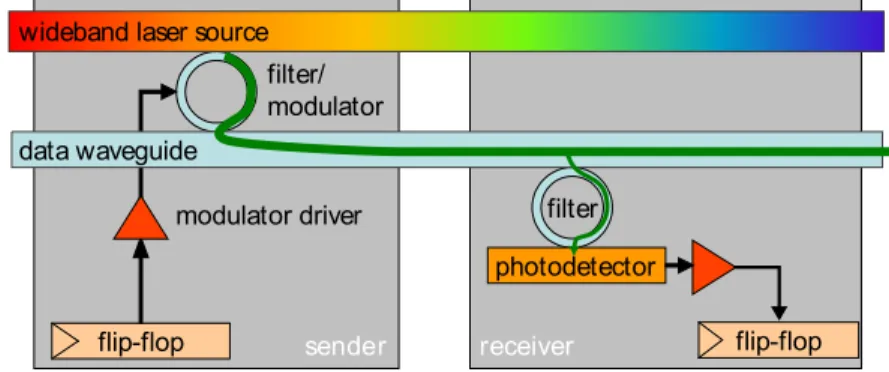
Advances in optical communication technologies have enabled the integration of op-toelectronic components with standard CMOS fabrication. [7] All-to-all computing (ATAC), suggested by James Psota in [5], leveraged the optical communication tech-nology to eliminate communication contention. ATAC uses Wavelength Division Mul-tiplexing (WDM) to allow a single optical waveguide to simultaneously carry multiple independent signals on different wavelengths. Also, the optical waveguide can trans-mit data at a higher speed than its electronic counterpart. This capability virtually eliminates the heterogeneous distance-dependent cost function for communication.
Figure 2-1 shows the process of sending a bit from one core to another. A
mod-sende receive flip-flop flip-flop filter photodetector filter/ modulator modulator driver data waveguide
wideband laser source
r r
Figure 2: Optical transmission of a single bit
guide and confine light by a combination of a high-refractive-index material on the inside of the waveguide and a low-refractive-index material on the outside (the cladding). Waveguides can be made out of either silicon (Si) or polymer. Due to the fact that Si waveg-uides can be packed onto a chip at much higher densities and that modulators for Si can be made much more compactly, the ATAC design employs Si waveguides. These waveguides can be manu-factured in a standard CMOS process, as both the waveguide and cladding materials are commonly used elsewhere. ATAC requires waveguides with losses of less than 0.3dB/cm and total power ca-pacity of about 10 mW, both of which are achievable with Si.
The optical filter is a ring resonator that couples only a specific wavelength from the power supply waveguide to the data waveg-uide. The exact wavelength, as well as the spacing between wave-lengths, is determined by the ring resonator dimensions and is fixed during manufacturing. Limited tuning can be achieved by chang-ing the rchang-ing’s temperature or by injectchang-ing charge into the rchang-ing. The modulator is an optical device that imprints a digital signal on the light extracted by the filter by varying the absorption in the de-vice. Modulators are used to translate an electrical signal (ampli-fied by the modulator driver) into an optical signal, and can there-fore be thought of as an “optical switch”, placing values onto op-tical waveguides. The modulators are Ge based electro-absorption modulators with integrated filters. The ring resonators are not used for modulation but just for wavelength filtering. It is assumed that athermal design [31] is implemented, so that the rings do not need to be tuned. The modulators used in the ATAC design have char-acteristics that are expected to be reached by designs available in 2012: insertion loss of 1dB; area less than 50 µm2; modulation
rate of 1 Gbps; energy required to switch less than 25 fJ; and power consumption of 25 µW at 1 GHz [14].
At the receiving end of a waveguide, additional components are used to receive the signal and convert it to an electrical signal. An additional optical filter is used to extract light of a particular wave-length from the data waveguide and transfer it to a photodetector. The filter can be designed to extract any fraction of the total sig-nal by adjusting the size of the gap between the waveguide and the filter. The photodetector is an extremely sensitive optical device which absorbs photons and outputs an electrical signal. The pho-todetector proposed for ATAC has a responsivity of greater than 1 Amp/Watt and 3dB bandwidth performance at 1 GHz. It has an area footprint of less than 20 µm2. Furthermore, the expected
capacitance of the photodetector is less than 1 fF [7]. In current technology nodes, the output of the photodetector would need to be amplified by a power-hungry TIA (transimpedance amplifier) be-fore it could be used to drive a digital circuit. However, starting with the 22nm node, the smaller transistor input capacitances will allow the photodetector to directly drive a digital circuit, greatly reducing power consumption.
Figure 2 puts all of these elements together, showing how one bit
is transmitted from a flip-flop of one core to a flip-flop of another core. In this figure, the core on the left shows the components rel-evant to sending and the core on the right shows the components relevant to receiving; however, in the actual chip all cores would contain both sets of components. From end to end, the process for sending a bit on the ATAC’s optical network is as follows. The flip-flop signals the modulator driver to send either a 0 or a 1. The mod-ulator driver, which consists of a series of inverter stages, drives the modulator’s capacitive load. The modulator couples light at its pre-tuned wavelength λi from the optical power source and encodes
either a 0 or 1 onto the data waveguide. The optically-encoded data signal traverses the waveguide at approximately one-third the speed of light and is detected by a filter that is also tuned to wave-length λi. Photons are detected by the photodetector and received
by a flip-flop on the receiver side. Note that Figure 2 shows where a TIA would be needed to amplify the photodetector output, even though it would not be necessary for an ATAC chip since ATAC targets the 16nm technology node.
3. ARCHITECTURE OVERVIEW
As previously illustrated in Figure 1, the ATAC processor uses a tiled multicore architecture combining the best of current scalable electrical interconnects with cutting-edge on-chip optical commu-nication networks. The ATAC architecture is targeted at 1000-core chips implemented in a 16nm process. However, it can also be scaled down to smaller chips. In this paper we describe and evalu-ate 64- and 1024-core versions. We first review the baseline elec-trical architecture, and then describe how it is augmented with the optical interconnect.
The underlying electrical architecture consists of a 2-D array of processing cores connected by a conventional point-to-point, packet-switched mesh network (called the EMesh) like those seen in other multicore processors [23, 12, 11]. Each core in ATAC contains a single- or dual-issue, in-order RISC pipeline with data and instruction caches (Figure 1(c)). ATAC uses a novel directory-based cache coherence scheme with a portion of the directory in each core (see Section 4).
To this electrical baseline, we add a global optical interconnect— the ANet—based on state-of-the-art optical technology. Whereas the EMesh is ideal for predictable, short-range point-to-point com-munication, the ANet provides low-latency, energy-efficient global and long-distance communication. The key component of the ANet is the all-optical ONet shown in Figure 1(a). In the 1024-core ATAC architecture (called ANet1024), cores are grouped into 64
“clusters”, each containing 16 cores. Each cluster contains a single ONet endpoint called a Hub. The Hub is responsible for interfac-ing between the optical components of the ONet and the electrical components within a cluster. The ATAC architecture can be scaled down by reducing the number of cores with each cluster. A 64-core chip (called ANet64) would connect each core directly to a Hub.
In ANet1024, individual cores are connected to the Hub in two
ways: data going from a core to the hub uses the standard EMesh (described above); data going from the Hub to the cores uses the BNet, a small electrical broadcast network (Figure 1(b)). In the 22nm node, the clusters are small enough that a flit can travel from the Hub to all cores in a cluster within one clock cycle. Because the BNet is dedicated to broadcasts, it is essentially a fanout tree and requires no routers, crossbars, or internal buffering. It requires only a small amount of buffering and arbitration at the Hub and receiving buffers at the leaves. We estimate that a BNet requires less than one-eighth the area of a full EMesh of the same bitwidth. The ANet1024uses a 128-bit wide ONet (128 optical waveguides
for data); one bit wide electrical EMesh; and two parallel 128-Figure 2-1: Optical transmission of a single bit. [5]
ulator is an optical component that writes 0 or 1 onto the network. Each core is equipped with one modulator per bit statically tuned to a frequency that is dedicated to that core. The modulator is controlled by a driver.
The optical signal is transmitted over a silicon waveguide at approximately one-third the speed of light. The signals pass optical filters, each statically tuned for a particular wavelength. The filtered signals are received by photodectectors.
Chapter 3
Overview of all-to-all
communication (ATAC)
architecture
3.1
Architecture for all-to-all communication
The efficient broadcast-based all-to-all communication (ATAC) requires several sets of hardware. Using optical network, hardware filtering, and message buffer, the fast and efficient broadcast is realized. This section describes the architectural components for the high performance broadcasting.
3.1.1
Broadcast on optical network
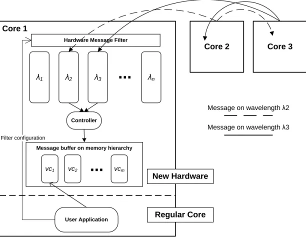
Broadcast-based inter-core communication leverages an optical network. Every core on a chip is connected by a single optical network. Each core is assigned to use a spe-cific frequency to broadcast a message over the optical network without interference. Since different cores use different wavelengths to broadcast, there is no contention between cores.
Although a core can send a message at anytime, it may receive messages from mul-tiple cores at the same time. To guarantee delivery of a message to other cores, FIFO
Core 1 Core 2 Core 3 λ1 λ2 λ3
...
λn Optical Network Message on wavelength λ2 Message on wavelength λ3 Hardware Message FilterFigure 3-1: Diagram of optical network broadcast
queues, called lambda queues, are introduced for each core. Each core is equipped with separate lambda queues for each wavelength (corresponding to the senders.), and the queues are called lambda queues. A broadcast message arrives at the corre-sponding lambda queue of its wavelength at each receiver core. (See figure 3-1)
3.1.2
Hardware message filtering
On our target manycore machine, the number of broadcast messages from all cores would be too large to be processed by a core. To resolve the issue, hardware message filtering is introduced. Each message arriving to a core is filtered through hardware message filter set by user, so that only recognized messages are buffered in queue. (See figure 3-1) The hardware filter simply consists of mask, bitwise operation, and signature. The filter first masks bits of a message signature and performs bitwise operations (and, or, xor) with the filter’s signature. A user may configure the filter of a specific core by setting filter mask, operation and signature. To handle concurrent message arrivals, there is a set of parallel filters for each wavelength. All filters on a core share the same configuration.
3.1.3
Virtual channel and message buffer
To facilitate the use of new broadcast-based inter-core communication, channel-like new API is introduced. A user may create a channel for a specific use, and restrict a broadcast message to be delivered to only subscribing cores. Although channel-like API is used, hardware only pads messages with a channel number. Thus, we call it “Virtual Channel” meaning no real communication channels exist. A user may create multiple virtual channels for different purposes. Broadcast or reception of a message happens on a specific channel. (For detailed description of API, refer Section 3.2)
For a quick retrieval of a message from user applications, message buffer organizes and stores messages from all senders by virtual channel id. As shown in figure 3-2, a controller loops around the lambda queues and transfers messages to the message buffer layer which is organized by channel id. The data storage for message buffer leverages regular memory hierarchy, which is expected to primarily utilize local caches.
3.2
Virtual channel interface for ATAC
architec-ture
A new channel-like API, called virtual channel, is introduced to ease the use of the broadcast-based inter-core communication. A message broadcast on a virtual channel is only delivered to its subscribers. In this section, the structure of a message encoding, and the API of the virtual channel are described.
3.2.1
Structure of message
To support filtering and virtual channel, a broadcast message is wrapped with extra information. In figure 3-3, the message has user tag, size of data, message signature for filtering, virtual channel id, and wavelength.
Core 1
Core 2 Core 3
λ1 λ2 λ3
...
λnMessage on wavelength λ2 Message on wavelength λ3
Hardware Message Filter
Controller
Message buffer on memory hierarchy
vc1 vc2
...
vcmUser Application
Filter configuration
New Hardware
Regular Core
Figure 3-2: Diagram of whole architecture
Size of Data <32bit> Data <Variable Length> Virtual Channel ID <32bit> Signature <32bit> Wavelength <32bit>
3.2.2
Virtual channel
Virtual channel is a new style of programming for inter-core messaging. This supports fast contention-free broadcast messaging among cores. API for virtual channel is easy to use: a user creates a virtual channel and spawn a virtual channel port on each thread. Core API functions are shown below.
1 c l a s s V i r t u a l C h a n n e l { p u b l i c: 3 s t a t i c V i r t u a l C h a n n e l ∗ c r e a t e ( ) ; i n t g e t i d ( ) ; 5 } ; 7 c l a s s V i r t u a l C h a n n e l P o r t { p u b l i c: 9 V i r t u a l C h a n n e l P o r t ( V i r t u a l C h a n n e l ∗ vc ) ; b o o l r e c e i v e m e s s a g e ( Message& m s g b u f f e r ) ; 11 b o o l s e n d m e s s a g e (i n t p a y l o a d b y t e , i n t m e s s a g e s i g n a t u r e , i n t t a g ) ; b o o l s e t l o c a l f i l t e r (i n t f i l t e r m a s k , i n t f i l t e r m a t c h o p e r a t i o n , i n t f i l t e r s i g n a t u r e ) ; 13 } ;
A user may create a virtual channel using the create method, which allocates an unused virtual id (Channel id is not exposed to application for usability and security.) To send and receive message, virtual channel port for a virtual channel should be created on each core. The example of use is shown below.
1 V i r t u a l C h a n n e l ∗ vc1 ; 3 i n t main (i n t a r g c , c h a r ∗∗ a r g v ) { vc1 = V i r t u a l C h a n n e l : : c r e a t e ( ) ; 5 f o r(i n t i = 1 ; i < n um t hr e a ds ; i ++){ SpawnThread ( t h r e a d f u n c , i ) ; 7 } } 9 21
v o i d∗ t h r e a d f u n c (i n t t h r e a d i d ) { 11 V i r t u a l C h a n n e l P o r t ∗ vcp = new V i r t u a l C h a n n e l P o r t ( vc1 ) ; 13 vcp−>s e n d m e s s a g e ( p a y l o a d b y t e = 1 , m e s s a g e s i g n a t u r e = 1 , t a g = 0 ) ; 15 Message msg ; vcp−>r e c e i v e m e s s a g e ( msg ) ; 17 p r i n t f (”msg : %s \n”, rank , msg . t o s t r i n g ( ) . c s t r ( ) ) ; }
Chapter 4
Performance modeling on Graphite
simulator
To measure the performance of the new all-to-all communication architecture, I adopted an open-source multicore simulator, called Graphite, which is developed by MIT carbon research group. [10] The simulator models system performance and power usage quite accurately. For this research, the simulator is modified to accom-modate the new broadcast-based communication and model its performance. (Power usage is not modeled.)
4.1
The performance model
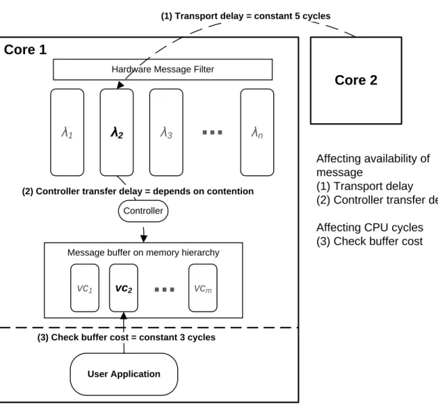
The performance model for the all-to-all communication architecture is composed of two big parts: message delay modeling and CPU cost modeling. When a core broadcasts a message, it takes time to arrive at the message buffer of a receiver. The latency of delivery comes from two parts: optical network latency (from sender to receiver’s lambda queue) and controller transfer delay (from lambda queue to message buffer.) This message delivery delay becomes important if a user application waits for the message.
Other than the time delay for a message to be ready for retrieval, there is a pure CPU cost for an application to take a message from a local message buffer.
Component Cycles needed Optical network transport 5 Controller transferring a message 10 Checking message buffer 3
Table 4.1: Default performance modeling parameters
(1) Transport delay = constant 5 cycles
Core 1
Core 2
λ
1λ
2λ
3...
λ
nHardware Message Filter
Message buffer on memory hierarchy
vc1 vc2
...
vcmUser Application
(2) Controller transfer delay = depends on contention
Controller
(3) Check buffer cost = constant 3 cycles
Affecting availability of message
(1) Transport delay
(2) Controller transfer delay Affecting CPU cycles (3) Check buffer cost
4.1.1
Message delivery delay from optical network
The message’s delivery among cores happens over an optical network. As ATAC ar-chitecture guarantees the contention-free broadcast by utilizing various wavelengths, the transport latency over the optical network stays constant. According to the specifications of the real optical network hardware, the latency is expected to be 5 cycles. [12]
4.1.2
Message delivery delay from controller transfer
Messages in lambda queues should be transferred to a message buffer before retrievals by applications. A hardware controller loops around lambda queues and transfers a message to the corresponding location in the message buffer. For the simplicity of hardware design, the controller transfers only one message at a time. Thus, if many messages arrive at local lambda queues, contention in the controller causes extra delay of message delivery.
In our performance measurement, we assumed that the controller takes 10 cycles to transfer a message. The contention delay among messages for this controller is modeled by the Graphite’s contention tree shared-resource model, which is described in Section 4.3.2.
4.1.3
CPU cost for retrieving a message from buffer
When a user application checks and retrieves a message from a message buffer, CPU cycles are consumed. Similar to memory referencing, this cost depends on the pipelin-ing algorithm of a core. In our experiment, we assumed constant 3 cycles to retrieve data from a message buffer.
4.2
Key parts in Graphite
An open-source multicore simulator, called Graphite, is used to model performance of ATAC architecture. The stock version of the simulator models multicore system
Key Simulator Components
Physical Transport Host Machine MCP LCP Target Core Target Core Target Core Target Core Host Machine LCP Target Core Target Core Target Core Target Core Host Machine LCP Target Core Target Core Target Core Target Core 11 Application Thread MessagingAPI Memory System Target Network Model
Transport Layer
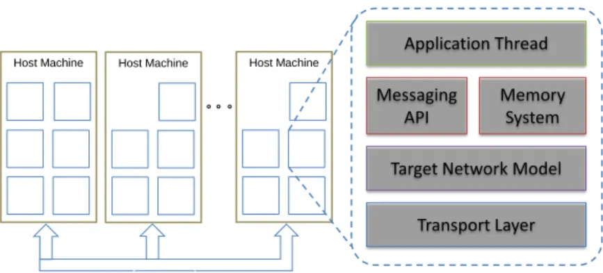
Figure 4-2: Graphite’s key simulator components: each target core has application thread, messaging API, memory system, network model, and transport layer. [11]
performance quite accurately. The simulator was modified to support broadcast-based communication and model its performance according to the model described in section 4.1
Graphite is an application-level simulator based on dynamic binary translation, which uses Intel’s Pin dynamic binary instrumentation tool. During Graphite’s sim-ulation, an application runs natively except for new features or modeled events. For such exceptions, Graphite traps the execution and models functionality and tim-ing. [10]
For the new features or modeled events, Graphite simulator has three parts: inter-nal functiointer-nality, performance modeling, and user interface. The first one, the interinter-nal functionality portion, enables simulation of application code. The performance mod-eling part models and counts CPU cycles by instructions. The last part, interface, supports system API on Graphite simulation system (especially for instructions not supported by popular modern architectures). [11]
4.3
How to model the performance on Graphite
To support broadcast-based communication, Graphite’s communication stack has been modified. As shown in Figure 4-2, graphite has application thread, messag-ing API, memory system, network model, and transport layers per core. Among those layers, messaging API and network model layers were modified to support new
ATAC features.
I leveraged Graphite’s network and transport models which can broadcast a mes-sage and modified its performance model to reflect the correct ATAC cost model described in Section 4.1.
4.3.1
Implementation of functionality on Graphite
To support the functionality of hardware filtering, lambda queues, and message buffer, new components whose class names are filtered ingestor and message buffer are created.
Filtered ingestor class incorporates the functionality of hardware filters and lambda queues. The class takes a message from Graphite’s original network layer, applys a hardware filter, and saves it to a lambda queue. As described in Section 3.1.1, the message falls into a corresponding lambda queue with respect to its wavelength. Message buffer class functions as a message buffer which organizes message by virtual channel. This class is just a storage for messages and their latency information. The calculated delay of a message is saved with the message itself to determine its availability and CPU cycle cost if an application waits for it.
In addition to those two new components in Graphite, core and network are mod-ified. The network layer is modified to support new features, such as checking avail-ability of a message on the network layer of a core. Core is modified to support hardware filter setting instruction and send/receive of a broadcast message (with their cost calculations). Figure 4-3 lists the places where Graphite code is modified.
Graphite uses Intel Pin dynamic binary instrumentation tool. To support new instructions (such as sending/receiving a message and setting hardware filter), the Pin’s routine replace part should be modified. When routine replace finds match-ing function calls from application code, it traps and replaces it with Graphite’s internal code, so that the functionality and the cost modeling is handled by Graphite instead of running natively. A user application can access interfaces under the /common/user/ directory, but such function calls should be replaced by Pin before it can reach Graphite’s internal codes.
pin routine replace.cc common atac network network.cc models
network model magic.cc .2 tile core
core.cc
core model.cc instruction.cc models
iocoom core model.cc simple core model.cc user capi.cc carbon user.cc atac user.h common.h message.cc virtual channel.cc
Figure 4-3: Locations of modifications on Graphite (.h header file is omitted in case .cc file is in the list.)
4.3.2
Performance modeling on Graphite
The performance model of ATAC architecture has three big parts as mentioned in Section 4.1.
The message latency from the optical network stays constant. Since we lever-aged graphite’s network layer, simply changing the network model of Graphite suf-fices. Graphite comes with a “magic” network model, which assigns constant la-tency to all messages. To use that model, configuration in the carbon sim.cfg file should be changed: the value for network/user model 1 should be “magic.” Also network model magic.cc file has to be changed to reflect the correct latency value.
The transfer delay from the controller is trickier to model. Graphite is an asyn-chronous simulator, which allows time skew among target cores. This means that a message whose arrival time is later may arrive before the message whose time is earlier. This property poses a difficulty for modeling controller transfer delay, which varies by contention. Because of such timing difficulties for shared resources, Graphite pro-vides a tool, queue model, to estimate such contention delay from shared resources. Especially, a history tree model is used in ATAC modeling; it stores utilization history as sets of free intervals and computes delay by the distance from message time and nearest available free interval. The detail of how the history tree works is shown in pages 30-36 of the “model details” slide section in [11]. The calculated controller transfer delay is then saved with the message to message buffer and used when an application tries to retrieve the message.
Retrieving a message from a message buffer actually incurs CPU cycles on a target core. This cost varies by all the latencies modeled. If the message is available when an application checks a message buffer, it only costs three cycles. However, if a message is not available, and the application waits for the message, extra cycles for wait time is incurred (difference between current core time and message arrival time). To incur correct cost, varying by situation, dynamic instruction should be used. The function call of retrieval of a message is considered to be an instruction in Graphite. To support this new instruction, a Check Buffer dynamic instruction is implemented. A core
of graphite calculates the correct cost of a retrieval and queues the Check Buffer dynamic instruction with corresponding cost. The queued instruction is handled by the original Graphite system, which keeps target CPU time correct.
4.3.3
How to run simulation
Many common applications can run on Graphite. As long as an application is com-patible with Graphite, it can also use ATAC architecture. To use broadcast-based communication, a user has to include atac user.h. The APIs for ATAC features are listed in Table 4.2.
One thing to be cautious about is that a user has to modify his/her code before using ATAC features. Before calling virtual channel API functions, an application must specify CAPI rank using CAPI Initialize and set a barrier across all cores using ATAC features to make sure all threads are initialized with correct rank value. Most parallel programs assign a thread to a core with sequential thread id. In such cases, a user may simply use thread id as rank in Graphite.
After those changes, a user may run his/her application by following a standard procedure to run an application on Graphite. [11]
As the user application finishes, the sim.out file includes additional performance statistics: the number of messages received, the number of messages through con-troller, and the average packet delay.
VirtualChannel class static
VirtualChannel*
create()
Creates a new virtual channel with new id assigned automatically.
VirtualChannelPort class
Constructor VirtualChannelPort (VirtualChannel *vc) Creates a new port for a virtual channel. bool receive message (Message& msg buffer)
If there is a message corresponding to this VirtualChannel, then it copies the message in msg buffer and returns true. Otherwise, returns false.
bool receive message long (Message& msg buffer, char* data buffer, int data size)
If there is a message corresponding to this VirtualChannel, then it copies the message in msg buffer, copies data along with message in data buffer and returns true. Otherwise, returns false.
bool wait and receive message (Message& msg buffer)
Blocks until a message corresponding to this VirtualChannel arrives, then it copies the message in msg buffer and returns true. If it fails, returns false.
bool wait and receive message long (Message& msg buffer, char* data buffer, int data size)
Blocks until a message corresponding to this VirtualChannel arrives, then it copies the message in msg buffer, copies data along with message in data buffer and returns true. If it fails, returns false.
bool send message (int payload, int message signature, int tag) Broadcast a message with the specified attributes through this virtual channel. Returns true if succeed, false otherwise. bool send message long (char* data, int data size, int
message signature, int tag)
Broadcast a message with the specified attributes and extra variable length data through this virtual channel. Returns true if succeed, false otherwise.
bool set local filter(int mask, int match operation, int signature) Configure the hardware filter of a local core with the specified attributes. Returns true if succeed, false otherwise.
Table 4.2: API of Virtual Channel and Virtual Channel Port
Chapter 5
Applications of ATAC on parallel
programming APIs
The efficient broadcast-based messaging system of ATAC can be used in many appli-cations to improve their performance. However, the modifying program to utilize the new communication feature means extra work for programers. Thus, two commonly used parallel programming APIs—barrier and work stealing— are re-implemented by utilizing the broadcast-based messaging. Programmers may just replace existing barriers or work stealing with new versions which utilize the efficient broadcast-based communication.
5.1
Barrier
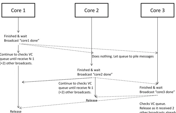
Barrier is a very popular parallel programming API. Every parallel programming language or library comes with its barrier implementation for synchronization (names may vary from barrier to synchronization). In fact, barrier is a very good example where broadcasting helps a lot since every core has to know every other cores’ status. The basic strategy of broadcast-based barrier is very simple: a core broadcasts out its finish over a virtual channel, and waits for other cores’ broadcast messages until it receives from all other cores. Since ATAC architecture saves messages until retrieval (as long as correct filtering and virtual channel subscription are done before), a core
Core 1 Core 2 Core 3
Finished & wait Broadcast “core1 done”
Finished & wait Broadcast “core2 done”
Does nothing. Let queue to pile messages
Finished & wait Broadcast “core3 done” Checks VC queue. Release as it received 2 other broadcasts already. Continue to checks VC
queue until receive N-1 (=2) other broadcasts.
Release
Release Continue to checks VC queue until receive N-1 (=2) other broadcasts.
Figure 5-1: How broadcast-based barrier works.
can retrieve finish messages from all other cores regardless of order.
Figure 5-1 shows how broadcast-based barrier works. When a core finishes its job and hits a barrier, it broadcasts out its finish and waits for messages from other cores. As the count of messages reaches N − 1 (N is the number of threads), it exits the barrier and proceeds.
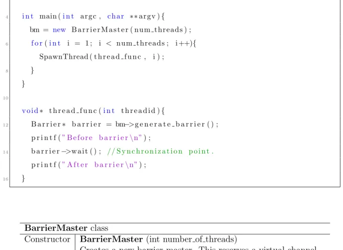
API for this barrier is similar to that of Pthread, which is familiar to most pro-grammers. For brevity, the broadcast-based barrier is named as a VC barrier (short for virtual channel based barrier). Instead of the pthread barrier t instance, Bar-rierMaster class functions as global reference to a barrier. A user has to initialize an instance of BarrierMaster with a number of threads. After initialization, each thread should generate a Barrier object using the generate barrier() function of an instance of BarrierMaster. The user may put barrier.wait() where synchronization is needed. A full list of API functions for VC barrier is in Table 5.1. A simple example of barrier usage is the following.
/∗ Example o f VC b a r r i e r ∗/
4 i n t main (i n t a r g c , c h a r ∗∗ a r g v ) { bm = new B a r r i e r M a s t e r ( n u m t hr e a ds ) ; 6 f o r(i n t i = 1 ; i < n um t hr e a ds ; i ++){ SpawnThread ( t h r e a d f u n c , i ) ; 8 } } 10 v o i d∗ t h r e a d f u n c (i n t t h r e a d i d ) { 12 B a r r i e r ∗ b a r r i e r = bm−>g e n e r a t e b a r r i e r ( ) ; p r i n t f (” B e f o r e b a r r i e r \n”) ; 14 b a r r i e r −>w a i t ( ) ; // S y n c h r o n i z a t i o n p o i n t . p r i n t f (” A f t e r b a r r i e r \n”) ; 16 } BarrierMaster class
Constructor BarrierMaster (int number of threads)
Creates a new barrier master. This reserves a virtual channel for barrier use.
Barrier* generate barrier ()
Generates a barrier access for the local core. This generates a VirtualChannelPort internally.
Barrier class
void wait ()
Indicates synchronization point. Broadcasts its finish and blocks until all other cores call wait() as well.
Table 5.1: API of broadcast-based barrier: BarrierMaster works as global barrier object and Barrier class is an access point from a core.
5.2
Work stealing
Work stealing job distribution is supported in many parallel programing libraries (TBB, Cilk++, MS PPL). Most such work-stealing implementations assume that there is exactly one work queue per thread. [4] They first try to retrieve a work from
their own local queue. If the queue is empty, they try to steal from queues in other cores. A difficulty comes from figuring out which queues to look in; scanning queues serially for work is very expensive and may cause a serious contention among threads looking for work.
At this point, there is an opportunity to improve performance using the cheap broadcasting ability: we can utilize the cheap broadcasting to figure out which core is most appropriate as a victim.
Two different prototypes for the new work-stealing system are implemented. The basic strategy is the same for all implementations; a thread with low or empty lo-cal queue broadcast out “request to share work” and other cores with enough work respond to the message. The ways of resolving contention while dequeuing a work among the local core and remote cores are different for the two implementations. The first version is similar to existing ones: double-ended queue with mutex is used for each local queue, and remote thieves compete to grab the mutex of a victim. The second version is a bit more complex; it does not have any mutex, and uti-lizes compare-and-swap on an item in a queue. In this version, the owner of a local queue actively suggests a particular item on its queue to thieves, and the thieves may dequeue items in parallel without any contention.
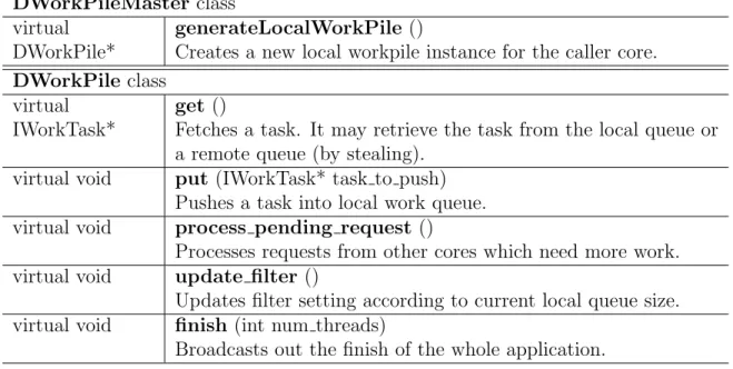
Table 5.2 lists user API functions for the work-stealing systems. The API is a wrapper interface for the various implementations described above. Similar to virtual channel and barrier, a user has to create a DWorkPileMaster instance first, and DWorkPile which serves as an access point for a local queue and the whole system.
5.2.1
Double-ended local queues with mutex implementation
for work stealing
In this version of work-stealing implementation, each core has a double-ended queue with a mutex. (See Figure 5-2.) All local accesses (put or get) are made through the top end of local queues, and remote steals of jobs are through the bottom end of the queues.
DWorkPileMaster class virtual
DWorkPile*
generateLocalWorkPile ()
Creates a new local workpile instance for the caller core. DWorkPile class
virtual IWorkTask*
get ()
Fetches a task. It may retrieve the task from the local queue or a remote queue (by stealing).
virtual void put (IWorkTask* task to push) Pushes a task into local work queue. virtual void process pending request ()
Processes requests from other cores which need more work. virtual void update filter ()
Updates filter setting according to current local queue size. virtual void finish (int num threads)
Broadcasts out the finish of the whole application.
Table 5.2: API of broadcast-based work-stealing system: this list is general user inter-face for work-stealing system, which is composed of two virtual classes: DWorkPile-Master and DWorkPile. The two virtual classes are implemented in various versions, using different algorithms.
When a core lacks jobs to process, it broadcasts out a “request to share work”. Cores with enough work to share may respond to the request with an offer to take jobs. The thief who wants more work chooses jobs to steal among the offers from other cores. To transfer the jobs, the thief must grab the mutexes of their owners, which marshal concurrent dequeue trials from multiple thieves. These steps are displayed in Figure 5-3.
Since thieves broadcast out their requests, piling of the request messages may burden too much overhead for responders. The hardware filtering is used to reduce such overhead. A core changes its hardware filter according to its number of remaining jobs; the filter is set to accept messages if there are too many jobs in the queue, and it is set to decline if there are too few. For the moderate number of jobs to process, filter is set probabilistically by the function in Figure 5-4.
Local put Remote steal Local get Mutex Job Job Job Job ...
Figure 5-2: Local work queue for a double-ended queue with mutex version.
(3) Thief grabs the mutex of victim, and transfer jobs. Core1 Job Job Job Job Job Core2 Job Job Core3 Job Job
(2) Response with an offer to take jobs
Core1 Job Job Job Job Job Core2 Job Job Core3 Job Job
(1) Request to share work
Broadcast on optical network Point-to-point message Core1 Job Job Job Job Job Filter: All Core2 Job Job Filter: none Core3 Job Job Mutex Job Job
P ro b a b lit y o f s e tti n g fi lte r o p e
n Number of jobs in local queue
1
0
L H
L: sharing lowerbound H: sharing upperbound
Figure 5-4: Probabilistic filter setting
5.2.2
Parallel stealing with compare-and-swap
implementa-tion for work stealing
In this version of work-stealing implementation, each core has a queue without any mutex. (See Figure 5-5.) All local accesses (put or get) are made through the bot-tom end of local queues, and remote steals of jobs are made in parallel. This is a bit complex mechanism: a victim responds to a request to share work by memory addresses of jobs offered, and remote thieves may concurrently steal jobs from the victim. Taking a job (either steal or local get) is done by by trying compare-and-swap (CAS) on the item (specifying the address for the job) in queue; if it succeed, the CAS reset the item as 0, meaning job is taken.
The assignment of jobs to be offered is made only by the owner of the jobs. As shown in Figure 5-6, the owner (victim) keeps an index value, assigner, to keep track which jobs are offered to thieves already. The assigner starts from the top end (the opposite to local accesses) and loops the queue until a critical region which is exclusively reversed to be processed locally, which ensures that unnecessary overhead is avoided.
When a core lacks jobs to process, it broadcasts out a “request to share work”. Cores with enough work to share may respond to the request with an offer to take jobs. The thief who wants more work chooses jobs to steal among the offers from other cores. To transfer the jobs, the thief tries a compare-and-swap operation to reset the original job as 0, which guarantees only one thief or owner takes the job and
Local put Local get Job Job Job Job ... Assigner CAS by core 2 CAS by core 3 0
Figure 5-5: Local work queue for a parallel stealing with CAS version.
process it. These steps are displayed in Figure 5-6.
In this scheme, remote steals doesn’t directly shrink the size of queue, and just set values of queue items as 0 instead. To resolve the increasing size of queue, assigner acts like a garbage collector: when it loops the queue, the assigner checks whether the value of items are 0. If it is, it removes the taken item from the queue.
Core2 Core1 Job 0 Job Job Job Core3 Job Job
(2) Response with the pointer of an offered job
Core1 Job Job Job Job Job Core2 Job Job Core3 Job Job
(1) Request to share work
Broadcast on optical network Point-to-point message Core1 Job Job Job Job Job Filter: All Core2 Job Job Filter: none Core3 Job Job Job Fetch and CAS
(3) Thief copies the offered job, and tries compare-and-swap to set it as 0.
Filter: none
Figure 5-6: Steps of sharing jobs between threads.
Chapter 6
Performance benchmark of ATAC
parallel programming APIs
The two commonly used parallel programming APIs—barrier and work stealing— are benchmarked on many-core architecture. The performance of common applica-tions was greatly improved by simply replacing existing APIs with new ones, and the effect grows as the number of cores on a chip increases. This finding proves the common performance benefit of ATAC architecture on manycore systems.
6.1
Barrier
First, barrier is micro-benchmarked by measuring time for loops with barriers inside. Secondly, an application called Streamcluster, which is a part of PARSEC benchmark suite, is benchmarked. PARSEC is short for Princeton Application Repos-itory for Shared-Memory Computers, a benchmark suite designed for shared-memory parallel computing performance. [1, 3, 2] PARSEC is a very renowned as a benchmark for shared-memory parallel computing.
All benchmarks were performed on the Graphite simulator for a fair comparison. Graphite is configured to have at most 64 target cores, power modeling off, and a lax clock skew minimization strategy. Each target core is set to run at 1GHz with 4-way associative 32KB of L1 dcache whose access time is 1 cycle. The user messaging
network among cores is set to use the magic model (to reflect the cost of the ATAC model in 4.1). Additionally, the number of cycles required to transfer a message through a controller is set to 10, and retrieving a message from a message buffer is set to take 3 cycles unless mentioned otherwise.
The Graphite simulation was hosted on a dual quad-core Intel(R) Xeon(R) X5460 @ 3.16GHz system with 8GB of DRAM. The system ran Debian Linux with kernel version 2.6.32-5. Only one process on a machine was used for a benchmark to avoid issues in Graphite and obtain more accurate results.
6.1.1
Barriers in a loop
To purely measure the cost of barriers, timing a loop of barriers is used. A for-loop with a just barrier wait call inside is used. To compare the performance of barriers against existing implementations, Pthread barrier and sense-reversing barrier are selected as baselines.
The example code for the VC barrier benchmark is in below. Benchmark codes for Pthread and sense-reversing barriers are similar.
/∗ B a r r i e r i n l o o p benchmark ∗/ 2 c a r b o n b a r r i e r t r a n k b a r r i e r ; B a r r i e r M a s t e r ∗bm ; 4 i n t NUM LOOPS = 1 0 0 0 ; 6 i n t main (i n t a r g c , c h a r ∗∗ a r g v ) { bm = new B a r r i e r M a s t e r ( n u m t hr e a ds ) ; 8 f o r(i n t i = 1 ; i < n um t hr e a ds ; i ++){ SpawnThread ( b a r r i e r I n L o o p , i ) ; 10 } } 12 v o i d∗ b a r r i e r I n L o o p (i n t t h r e a d i d ) { 14 C A P I I n i t i a l i z e ( t h r e a d i d ) ; // I n i t i a l i z a t i o n f o r G r a p h i t e B a r r i e r ∗ b a r r i e r = bm−>g e n e r a t e b a r r i e r ( ) ; 16 C a r b o n B a r r i e r W a i t (& r a n k b a r r i e r ) ; // I n i t i a l i z a t i o n f o r G r a p h i t e
f o r(i n t l o o p = 0 ; l o o p < NUM LOOPS; l o o p++) {
18 b a r r i e r −>w a i t ( ) ; // S y n c h r o n i z a t i o n p o i n t .
}
20 }
The end-to-end runtime of the micro-benchmark is displayed in Figure 6-1. The graph shows the exponentially increasing runtimes of the simple sense-reversing barriers. The Pthread barrier does a better job than the sense-reversing one with a higher number of cores. The barrier using the virtual channel for broadcasting outperform other barriers with a high number of cores. Even for a machine with four or more cores, the virtual channel barrier does a better job.
0 0.05 0.1 0.15 0.2 0.25 0.3 1 2 4 8 16 32 64 Seconds Cores Virtual Channel Sense Reversing Pthreads 0 0.002 0.004 0.006 0.008 0.01 0.012 0.014 1 2 4 8 16 Seconds Cores Virtual Channel Sense Reversing Pthreads
Figure 6-1: End-to-end runtime of a loop of 1000 barrier waits: left graph shows all data including 32 and 64 cores. Full graph on the left shows exponentially increasing synchronization cost, and superb performance of virtual channel barrier. Graph on the right shows virtual channel barrier is good at smaller number of cores as well.
In addition to the end-to-end runtime measurement, the performance of each barrier wait is measured as well. The time span from the entrance of the last thread into barrier wait to the moment when the last thread exits barrier is called exit latency. Since the latency of an ideal barrier is zero, the exit latency is considered as a pure synchronization cost.
In Figure 6-2, the median values of measured exit-latency are displayed. The trend 45
of exit latency values are very similar to the end-to-end measurement in Figure 6-1, which proves the superb performance of virtual channel Barrier.
Median Exit Latency, Barrier in a Loop, 1000 Iterations 0 20 40 60 80 100 120 140 160 1 2 4 8 16 32 64 micro-seconds ( μ s) Cores Virtual Channel Sense-reversing Pthread
Figure 6-2: Median of exit-latency of barriers for a 1000 loop benchmark:
6.1.2
Streamcluster application in PARSEC benchmark suite
Streamcluster application in PARSEC benchmark suite tests the performance of an architecture for approximating the optimal clustering of a stream of data. It is a machine learning application with coarse-granular parallelism with a static load-balancing. This problem is representative of everyday use application since clustering is very widely used in many fields like a network security or pattern recognition, and many uses like real-time fraud detection have a continuous stream of data instead of data set.
The implementation of Streamcluster is divided into three repeating steps: get block, cluster locally, and consolidate centers. The application need to synchronize every loop to proceed. PARSEC provides a Pthread implementation, which provides a good baseline for our virtual channel barrier. For experiment, the existing Pthread barriers in Streamcluster are replaced with sense-reversing barriers and virtual chan-nel barriers.
Figure 6-3 shows the end-to-end runtime of Streamcluster with Pthread, sense-reversing, virtual channel versions of barriers.
End to End Times ‐ Streamcluster, Input=simtest 0 0.05 0.1 0.15 0.2 0.25 0.3 0.35 1 2 4 8 16 32 64 Seconds Cores Virtual channel Sense-reversing Pthread 0 0.002 0.004 0.006 0.008 0.01 0.012 0.014 0.016 0.018 0.02 1 2 4 8 16 Seconds Cores Virtual channel Sense-reversing Pthread
Figure 6-3: End-to-end runtime of Streamcluster with simtest input size: left graph shows all data including 32 and 64 cores. Full graph on the left shows expo-nentially increasing synchronization cost, and superb performance of virtual chan-nel barrier. Graph on the right shows virtual chanchan-nel barrier is good at smaller number of cores as well.
As in the barrier-in-loop application, the exit latency values are measured to gauge the performance of each barrier wait1.
In Figure 6-4, the median values of measured exit-latency are displayed. The trend of exit latency values are very similar to the end-to-end measurement in Figure 6-3, which indicates the superb performance of virtual channel Barrier.
6.1.3
Robustness test of ATAC architecture model
The benchmark results in Section 6.1.2 and 6.1.1 are based on the performance model defined in Section 4.1. Although the results support the claim that the ATAC architecture and virtual channel barrier outperform the existing ones, the correctness of the claim is still contingent with the validity of the performance model.
To strengthen the claim that the virtual channel barrier is much better, the per-formance measurements of the two applications are collected with much worse as-sumptions on the ATAC performance model.
Section 4.1 introduced the default assumptions on the ATAC performance model: (1) transport delay = 5 cycles, (2) Cycles to transfer though a controller = 10 cycles,
1Exit latency is a time span from the entrance of the last thread into a barrier to the moment
when the last thread exits the barrier.
Median Exit
Latency,
Streamcluster,
Input=simtest
0 20 40 60 80 100 120 140 160 180 200 1 2 4 8 16 32 64 micro-seconds ( μ s) Number of Cores Virtual channel Sense-reversing PthreadFigure 6-4: Median of exit-latency of barriers for Streamcluster with simtest input size:
and (3) check buffer cost = 3 cycles. For this robustness test, each parameter is changed to a more harsh value, and the end-to-end runtime is measured.
Figure 6-5 shows the effects of the worse parameters on end-to-end runtime of the barrier-in-loop application. In the three graphs, the leftmost point is the default value in Section 4.1, and x-axis is log10 scale. It is found that the virtual channel barrier is quite resistant to all three parameters. Especially, optical network transport delay can increase up to 200 cycles without sacrificing the application performance. (Even 20000 cycles of the delay just doubles the runtime.) For controller transfer delay, values up to 200 cycles give comparable performances. Check buffer cost directly increases the runtime, but it is not the biggest factor.
On the other hand, Figure 6-6 shows the effects of the worse parameters on the end-to-end runtime of Streamcluster application. Again, the leftmost point is default value in Section 4.1, but x-axis is now in linear scale. It is found that the virtual channel barrier is still quite resistant to all three parameters. Still, high optical network transport delay does not increase the end-to-end runtime of Streamcluster. For the controller transfer delay, values up to 200 cycles still give comparable performance. Check buffer cost again directly increases the runtime, but it is not the biggest factor.
Barrier Benchmark 64 cores 0 0.02 0.04 0.06 0.08 0.1 1 1000 seconds (1) Transport delay (optical network) 0 0.02 0.04 0.06 0.08 0.1 1 10 100 1000 (2) Cycles to transfer through controller 0 0.02 0.04 0.06 0.08 0.1 1 10 100 (3) Check buffer cost (cost to access queue)
Figure 6-5: Effects of performance model parameters on barrier-in-loop end-to-end runtime: the left-most point is default model parameter, and x-axis in log scale.
Streamcluster 64 cores 0.016 0.018 0.02 0.022 0 100 200 seconds (1) Transport delay (optical network) 0.016 0.018 0.02 0.022 0 100 200 (2) Cycles to transfer through controller 0.016 0.018 0.02 0.022 0 20 40 (3) Check buffer cost (cost to access queue)
Figure 6-6: Effects of performance model parameters on Streamcluster end-to-end runtime: the left-most point is default model parameter, and x-axis in linear scale.
6.2
Work stealing
Work stealing is benchmarked by measuring time for a consuming distributed work. Since our work stealing implementation targets 64 cores with sacrifice on overhead, work stealing is benchmarked only on 64 core architecture.
6.2.1
Synthetic benchmark with distributed simple work tasks
To benchmark the performance of our work stealing implementations, we measured the time spent to consume all work in queues. Since the initial distribution of work largely affects the runtime, the benchmark is performed with five different types of initial distributions: total skew, half, even, quarter, and random. Total skew
0 6400 1 2 3 4 5 … 63 64
Total Skew
0 100 200 1 2 3 4 5 … 63 64Half
0 50 100 1 2 3 4 5 … 63 64Even
0 200 400 1 2 3 4 5 … 63 64Quarter
0 50 100 150 1 2 3 4 5 … 63 64Random
x-axis: Core number y-axis: % of work (100% per core) (6400% total)
Figure 6-7: Initial distribution of work for synthetic benchmark: for random distri-bution, illustrated value is just an example.
distribution puts all work on a core, and rest has nothing initially. For the half and quarter distributions, half or quarter of cores have an even work distribution. Random distributes work randomly from normal variable. These distributions are illustrated in Figure 6-7
The work item for the benchmark is a combination of dummy floating point op-erations. Each work is set to consume about 0.12 mills on Graphite’s target core. This size shows a good balance to show both communication cost and work running time. (If the work size is too large, the difference in communication costs of various implementations becomes unnoticeable. Too small work size will mislead to zero work sharing.)
For the baseline of this benchmark, I developed additional two implementations for work stealing. First implementation has work queue style (modeling Java work queue), which has only one global work queue with a global mutex. Second one models the the Cilk style work stealing implementation which has work queues for every core and randomly picks a core to steal work from. [4]
This benchmark result shows how broadcasting helps choose a victim efficiently. In Cilk style work stealing, a thief randomly picks a victim without any knowledge of
0 10 20 30 40 50 60 70 80 470 480
Total skew Half Even Quater Random
Runtime (milliseconds)
Java-style: global queue Cilk-style: random steal VC-DEQueue w/ mutex VC-compare and swap
Figure 6-8: End-to-end runtime of work-stealing synthetic benchmark.
which core is more willing to share, and the style suffers when there is a huge skew in the distribution of work.
Figure 6-8 shows the end-to-end runtime of the benchmark. The performance of the virtual channel compare-and-swap (VC-CAS) version (described in Section 5.2.2) is outstanding for total skew, half, and quarter. All of the distributions where VC-CAS outperform others have idle cores at the beginning, and work needs to be dis-tributed. Cilk-style random stealing version has a slight advantage for even and random distributions where jobs are distributed quite evenly since they do not in-cur communication overheads. The performance of the virtual channel double-ended queue with mutex version (described in Section 5.2.1) is little worse than that of VC-CAS. Java-style global queue version relies only on cache coherence protocol and global mutex, it performs generally worse than other versions where each core has its own queue. The work queue version does best for total skew distribution, but this extreme distribution is not expected to appear in real applications much.
Chapter 7
Conclusions and future work
7.1
Conclusions
Through this project, we have designed and implemented a novel architecture for broadcast-based inter-core communication on manycore systems. As a result of the advances in on-chip optoelectronics, a cheap broadcasting of a message became possi-ble. Our design of the architecture allows a user application to broadcast and receive a message efficiently with an easy-to-use API, called Virtual Channel. This architec-ture is implemented on a Graphite simulator, which provides an accurate modeling of system performance.
To prove the benefits of the architecture, two commonly used parallel program-ming APIs are re-implemented in a way that utilizes the cheap inter-core broadcast-ing ability. The first one, barrier, outperformed existbroadcast-ing implementations (especially Pthread) with much simpler algorithm than theirs, proving the ease-of-use and formance of our architecture. Second parallel programming API, work stealing, per-formed better than other existing strategies when there is an actual imbalance of job distribution.
7.2
Future work
7.2.1
Benchmark work stealing with real applications
Due to the difficulty in finding famous and good benchmark for work stealing, only a synthetic benchmark was conducted. The difficulty was finding a benchmark which fits well with work stealing and is compatible with Graphite simulator. Since Graphite simulator only supports Pthread API for threaded programming, many benchmarks running on other platforms had to be excluded.
Recently, we found a good matching benchmark: Dynamic Graph Challenge devel-oped by Dan Campbell in Georgia Tech. We hope to run this problem as benchmark for our work stealing implementation very soon.
7.2.2
Running real parallel programming platforms as
base-lines
Instead of synthesizing baseline implementation according to existing algorithms, con-ducting benchmark directly with existing parallel programming platforms is preferred. We are now investigating on running Cilk++ on Graphite to benchmark its work stealing implementation as a new baseline.
Bibliography
[1] Christian Bienia. Benchmarking Modern Multiprocessors. PhD thesis, Princeton University, January 2011.
[2] Christian Bienia, Sanjeev Kumar, Jaswinder Pal Singh, and Kai Li. The parsec benchmark suite: Characterization and architectural implications. In Proceedings of the 17th International Conference on Parallel Architectures and Compilation Techniques, October 2008.
[3] Christian Bienia and Kai Li. Parsec 2.0: A new benchmark suite for chip-multiprocessors. In Proceedings of the 5th Annual Workshop on Modeling, Bench-marking and Simulation, June 2009.
[4] R.D. Blumofe and C.E. Leiserson. Scheduling multithreaded computations by work stealing. In Foundations of Computer Science, 1994 Proceedings., 35th Annual Symposium on, pages 356–368, 1994.
[5] James Psota et al. ATAC: All-to-All Computing Using On-Chip Optical Inter-connects. In BARC, 1/2007.
[6] Message P Forum. Mpi: A message-passing interface standard. Technical report, Knoxville, TN, USA, 1994.
[7] Randolph Kirchain and Lionel Kimerling. A roadmap for nanophotonics. Nature Photonics, 1(6):303–305, June 2007.
[8] Michael Kistler, Michael Perrone, and Fabrizio Petrini. Cell multiprocessor com-munication network: Built for speed. IEEE Micro, 26(3):10–23, May 2006. [9] George Kurian, Jason E. Miller, James Psota, Jonathan Eastep, Jifeng Liu,
Jurgen Michel, Lionel C. Kimerling, and Anant Agarwal. Atac: a 1000-core cache-coherent processor with on-chip optical network. In Proceedings of the 19th international conference on Parallel architectures and compilation techniques, PACT ’10, pages 477–488, New York, NY, USA, 2010. ACM.
[10] J. E. Miller, H. Kasture, G. Kurian, C. Gruenwald III, N. Beckmann, C. Celio, J. Eastep, and A. Agarwal. Graphite: A distributed parallel simulator for multi-cores. In Proceedings of the 16th International Symposium on High Performance Computer Architecture (HPCA), pages 1–12, January 2010.
[11] J. E. Miller, G. Kurian, N. Beckmann, E. Lau, S. Neumann, O. Khan, and D. Murrell. Graphite simulator tutorial at isca 2011, June 2011.
[12] Miller, Psota, Kurian, Beckman, Eastep, Beals, Michel, Lui, Kimerling, and Agarwal. ATAC: A Manycore Processor with On-Chip Network. In MIT Tech-nical Report, 2009.
[13] J. Psota, J. Miller, G. Kurian, H. Hoffman, N. Beckmann, J. Eastep, and A. Agar-wal. Atac: Improving performance and programmability with on-chip optical networks. In Circuits and Systems (ISCAS), Proceedings of 2010 IEEE Interna-tional Symposium on, pages 3325–3328, 2010.
[14] Michael B. Taylor, Walter Lee, Jason Miller, David Wentzlaff, Ian Bratt, Ben Greenwald, Henry Hoffmann, Paul Johnson, Jason Kim, James Psota, Arvind Saraf, Nathan Shnidman, Volker Strumpen, Matt Frank, Saman Amarasinghe, and Anant Agarwal. Evaluation of the raw microprocessor: An exposed-wire-delay architecture for ilp and streams. In Proceedings of the 31st annual inter-national symposium on Computer architecture, ISCA ’04, pages 2–, Washington, DC, USA, 2004. IEEE Computer Society.