ALTERNATIVE PASSIVE COOLING CONCEPTS FOR
A LARGE RATING PRESSURIZED WATER REACTOR CONTAINMENT by
Mirela Gavrilas B.S., Nuclear Engineering University of Maryland, 1990
Submitted to the Department of Nuclear Engineering in July 1995 in Partial Fulfillment of the Requirements for the Degree of
Doctor of Philosophy in Nuclear Engineering at the
Massachusetts Institute of Technology July 1995
© 1995 Massachusetts Institute of Technology All rights reserved
Signature of Author
, . Department of Nuclear Engineering
Certified by , Certified by
Professor Neil E. Todreas Department of Nuclear Engineering Thesis Advisor
Certified by
Professor Emeritus Michael J. Driscoll Department of Nuclear Engineering Thesis Advisor Accepted by
/
Profe or Jeffrey P. FreidbergChairman, Department Committee on Graduate Students Department of Nuclear Engineering r.'A. "S' Msrrs INsrT;•uTE
OF TECHNOLOGY
APR 2
2
1996
LIBRARIESALTERNATIVE PASSIVE COOLING CONCEPTS FOR
A LARGE RATING PRESSURIZED WATER REACTOR CONTAINMENT by Mirela Gavrilas
Submitted to the Department of Nuclear Engineering in July 1995 in Partial Fulfillment of the Requirements for
the Degree of Doctor of Philosophy in Nuclear Engineering
Abstract
The scope of this research project was the design of an integrated PWR containment concept that allows heat to be rejected passively to the environment. A state-of-the-art double enclosure containment (an Ebasco design) was modified, and augmented with several features that enhance heat storage, redistribution and rejection: primarily a 80 % increase in free volume and the addition of air/water inlet and outlet vents in the concrete shield to create an air-convection annulus, which allows air-cooling on the upper part of the shell; an external water pool, which covers the lower part of the containment; and an internal water pool, which is located at the bottom of the lower containment. The performance of the proposed passively cooled containment was evaluated using a subdivided volume code, GOTHIC Version 3.4e.
Two experiments were carried out to support the computer predictions. The first experiment was designed to test the performance of the external moat; it was shown that free convection is highly effective in the expected range of operation, and that the potential for thermal-stratification of the moat depends on the axial temperature distribution of the shell. The second experiment was used to verify the ability of the GOTHIC code to predict thermal-stratification of the in-containment atmosphere. A modeling technique (boundary layer model) was devised to properly estimate heat transfer along the containment shell, and thus the pressure limitation due to low-lying features.
An in-depth verification of modeling techniques, in general, and GOTHIC code logic, in particular, was performed. The impact of input variable selection (mesh sizes, subvolume characteristics, heat sinks, flow paths) was assessed. The ability of the GOTHIC code to accurately predict thermal stratification, the effect of asymmetries, and the boundary layer flow along the steel shell was verified.
A model of the proposed containment with all the features described was input into GOTHIC. The behavior of this integrated containment was evaluated for the worst-case large break loss of coolant accident and the worst-case main steam line break accident scenarios. The peak pressure predicted by the code for this containment configuration remained below 0.45 MPa during either transient. The proposed containment was shown to remain below all design limits (internal wall pressure differences, equipment qualification temperatures, pressure restoration time). The capability for hydrogen mitigation using recombiners was demonstrated.
Thesis Advisors:
Dr. Neil E. Todreas, KEPCO Professor of Nuclear Engineering Dr. Michael J. Driscoll, Professor Emeritus of Nuclear Engineering
Acknowledgments
The author expresses her most sincere appreciation to her advisors, Prof. Neil E. Todreas and Prof. Michael J. Driscoll, for their essential guidance and continuous encouragement. A great deal of gratitude is also due to Professors David Lanning and John Meyer for answering questions that arouse during the completion of this work, and for generously sharing their knowledge during course work. Professors Peter Griffith (M.I.T.) and Lothar Wolf (University of Maryland) are also acknowledged for their important suggestions. The many GOTHIC code runs would have been significantly curtailed without Tom George's (NAI) assistance. Many thanks also to Dr. Pavel Hejzlar for his collegiality and friendship. The help of Joseph Caloggero and Robert Nuthal in completing the experimental setup is also acknowledged.
The sponsorship of this work by the Electric Power Research Institute under contract RP3500-18 is also acknowledged.
Finally, the author wishes to express her deepest thanks to her mother for always having been supportive and inspiring.
5
Nomenclature
General English Notation A
C,
D De G g H h k L m rih p PQ0
q" R S T V v z Dimensionless Numbers gpq"D4 Gr q, = - Grashof number S kv2 hD e Nu = - -Nusselt number k Ra = Gr -Pr -Rayleigh number gfATD3 Gr = -Grashof number V2 Cp Pr = - Prandtl number k pvD e Re = - Reynolds number J-cross-sectional areaspecific heat, constant pressure diameter
hydraulic diameter (equivalent diameter) gap width
gravity height
heat transfer coefficient thermal conductivity characteristic length mass
mass flow rate pressure perimeter power heat flux radius surface area temperature volume velocity axial distance
Greek Symbols
3
thermal expansion coefficient A difference D uncertainty F surface emissivity g dynamic viscosity v kinematic viscosity nr. constant, 3.14159 p density o Stefan-Boltzman constant I summation Subscripts I state at time 1 2 state at time 2 air air atm atmosphere cond condensate condensation conv convection CMNT containment decaydecay heat
duct duct wall
eff effective
FC free convection
f liquid phase of water
fg liquid to vapor phase change
fibgl fiberglass
g vapor phase of water in inlet
j axial node number k radial node number loss heat loss
out outlet
moat moat
pool water pool PVC PVC pipe
rad radiative heat transfer RCCS reactor coolant system sat saturation
Subscripts (continued)
stm
steamtotal total quantity
vap vapor contained in the air vessel heated vessel
w wall wt water Superscripts average Acronyms BWR EPR EPRI FM GE HTC LBLOCA LOCA LWR MSLBA NAI
PCCS
PG
PWR
TC
boiling water reactor
European pressurized water reactor Electric Power Research Institute flow meter
General Electric
heat transfer coefficient
large break loss of coolant accident loss of coolant accident
light water reactor
main steam line break accident Numerical Applications Inc.
passive containment cooling system pressure gage
pressurized water reactor thermocouple
8 Table of Contents Abstract--- 3 Acknowledgments --- 4 Nomenclature --- 5 Table of Contents --- 8 List of Figures --- 12 List of Tables --- 17 CHAPTER 1. INTRODUCTION --- 18 1.1 Reactor Containments---19
1.2 Concepts for Passive Cooling of Large Rating LWRs --- 24
1.3 The Proposed Large Rating LWR Passively Cooled Containment--- 26
1.4 Available Analysis Tools --- 36
1.5 Organization of This Thesis --- --- 41
Chapter I References--- 43
CHAPTER 2. BACKGROUND -- THE STATUS OF PASSIVE CONTAINMENT COOLING --- 45
2.1 Considerations in Passive Containment Cooling --- 45
2.2 Small Rating Reactors --- --- 49
2.3 Large Rating Reactors --- --- 54
2.4 Containment Experimental Programs --- 57
2.5 Chapter 2 Summary --- 62
Chapter 2 References--- 65
CHAPTER 3. THE GOTHIC CODE --- --- 67
3.1 Containment Analysis Codes --- --- 68
3.2 Succession of GOTHIC Models for the Proposed Containment--- 73
3.3 Preliminary Run Optimization Steps for the GOTHIC Code --- 80
3.3.1 Nodalization Selection --- 82
3.3.2 Time-step Convergence--- 90
Chapter 3 References--- 93
CHAPTER 4. PROPOSED PASSIVE COOLING FEATURES --- 94
4.1 The Air-Convection Annulus --- --- 95
4.1.1 Axially-separated Air Inlets for Annulus convection--- 96
4.1.2 Convection Heat Transfer Correlations for GOTHIC --- 1--- 10
4.1.3 Performance Predictions for the Air-convection Annulus --- 1--- 15
4.2 The External Annular Pool --- --- 119
4.2.1 Performance Predictions and Sizing --- 119
4.3 The External Moat--- --- 126
4.3.1 Performance Predictions and Sizing --- 127
4.4 The Internal Water Pool --- --- 131
4.4.1 Performance Predictions and Sizing --- 132
4.5 GOTHIC Predictions for the Proposed Containment with Integrated Heat Rejection Features --- 134
4.6 Chapter 4 Summary --- --- --- 141
Chapter 4 References--- 145
CHAPTER 5. HEAT TRANSFER TO A LARGE MOAT --- 147
5.1 Moat-heat-transfer Experimental Apparatus --- 149
5.2 Moat Heat-transfer Coefficients --- 158
5.3 Chapter 5 Summary --- 169
Chapter 5 References--- 170
CHAPTER 6. THERMAL STRATIFICATION IN THE CONTAINMENT ATMOSPHERE --- 171
6.1 Factors Affecting Thermal Stratification --- 172
6.2 Thermal-stratification Experiment --- 176
6.3 Boundary-layer Cell GOTHIC Model --- 186
6.4 The Effect of Condensation Heat Transfer Correlations --- -210
6.5 Chapter 6 Summary --- 219
Chapter 6 References---222
CHAPTER 7. PROPOSED PRESSURIZED WATER CONTAINMENT DESIGN--- --- 223
7.2 Heat Rejection Mechanisms --- --- 230
7.3 Proposed Configuration---234
7.4 Chapter 7 Summary --- 240
Chapter 7 References---242
CHAPTER 8. ANALYSIS OF THE PROPOSED PRESSURIZED WATER CONTAINMENT DESIGN --- 243
8.1 The GOTHIC Model for the Proposed Containment--- 244
8.1.1 Input Parameter Adequacy --- --- 249
8.1.2 Phenomena Simulation Adequacy --- 257
8.2 Large Break Loss of Coolant Accident --- 272
8.3 Main Steam Line Break Accident --- --- 283
8.4 Hydrogen Release Accident Scenarios --- 291
8.5 Chapter 8 Summary --- 300
Chapter 8 References---304
CHAPTER 9. SUMMARY, CONCLUSIONS AND RECOMMENDATIONS FOR FUTURE WORK---305
9.1 Summary and Conclusions---305
9.1.1. Background --- 308
9.1.2. Preliminary GOTHIC Code Verifications --- 3--- 13
9.1.2. Pressure-limiting Features --- 315
9.1.3. The Moat Experiment --- 320
9.1.4. The Thermal-stratification Experiment --- 324
9.1.5. The Proposed Containment Design--- --- 332
9.1.6. The Performance of the Proposed Containment --- 334
9.2 Recommendations for Future Work --- --- 343
Chapter 9 References---345
APPENDIX A. REFERENCE CONTAINMENT DATA---350
APPENDIX B. CALCULATIONS FOR MULTIPLE AIR INLETS --- 397
APPENDIX C. BOUNDARY LAYER CALCULATIONS --- 405
APPENDIX D. POOL-HEAT-TRANSFER EXPERIMENT DATA REDUCTION AND ERROR ANALYSIS ROUTINES --- 411
11
D. 1 Data Reduction Routine--- --- 411
D.2 Error Analysis Routine --- --- 412
D.3 Moat Experiment Heat Loss Calculation --- 415
List of Figures
Figure 1.1 The proposed passively cooled containment for a large rating PWR ... 29 Figure 1.2 Heat removal mechanisms that limit the pressure excursion inside the containment
follow ing an accident ... 30 Figure 1.3 GOTHIC predicted 3 day pressure history in the proposed containment following a
large break LO C A ... 40 Figure 2.1 Schematic drawing of Hitachi's HSBWR containment [from Kataoka et al., 1990].. 51 Figure 2.2 Schematic drawing of B&W's ASPWR containment [from Menaker et al., 1990] ... 53 Figure 2.3 Schematic drawing of Westinghouses's AP600 containment [from van de Venne et
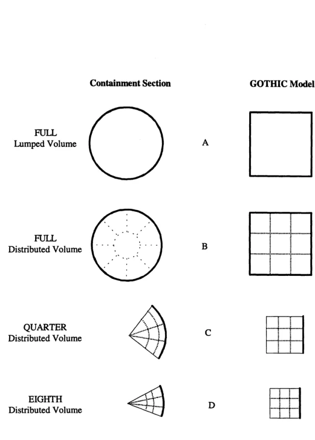
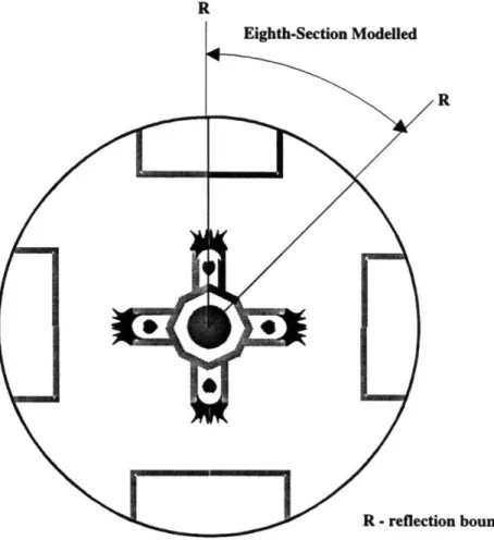
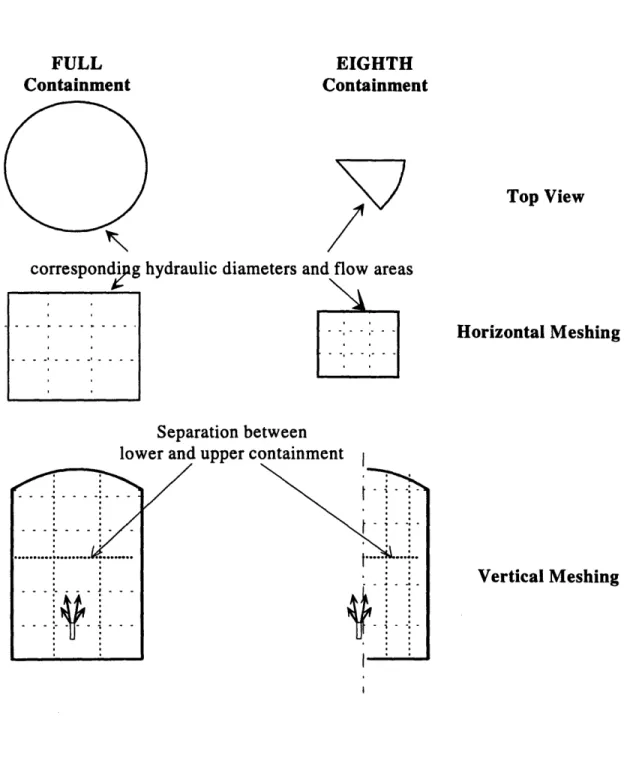
al., 1992] ... 55 Figure 2.4 A simple schematic of the MIT -- prefilled water annulus test apparatus ... 61 Figure 3.1 Cross section schematics of models A, B, C, and D ... 78 Figure 3.2 The four break release points in the full containment obtained using
mirror image repetition of an eighth-pie section... ... 81 Figure 3.3 The three-subvolume and five-subvolume containment
m odels for G O TH IC ... ... 84 Figure 3.4 Pressure and temperature histories for the three-subvolume containment following a
LO CA ... 84
Figure 3.5 Pressure and temperature histories for the five-subvolume containment following a
LO C A ... 84
Figure 3.6 The full- and eighth-containment models used in GOTHIC ... 86 Figure 3.7 Comparison of predictions obtained for the full- and eighth-containment models
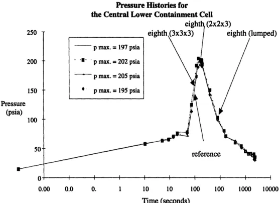
follow ing a LO C A ... 88 Figure 3.8 Comparison of predictions obtained for the eighth-containment
model with different nodalizations following a large break LOCA ... 89 Figure 4.1 A schematic of the expected air flow for multiple
axially-separated inlets... 93 Figure 4.2 Heat transfer coefficient as a function of temperature difference
between the containment and annulus wall for various air inlet temperatures... 94 Figure 4.3 Friction factor as a function of temperature difference between the containment
and annulus wall for various air inlet temperatures... 100 Figure 4.4a Heat transfer coefficients as a function of temperature difference
between the containment and annulus walls for various air inlet
temperatures for the bottom-open configuration ... 104 Figure 4.4b Friction factors as a function of temperature difference between the containment
and annulus walls for various air inlet temperatures for
the bottom-open configuration ... 104 Figure 4.5a Heat transfer coefficients as a function of temperature difference
between the containment and annulus walls for various air inlet temperatures
for the bottom-closed configuration... 105 Figure 4.5b Friction factors as a function of temperature difference between the
containment and annulus walls for various air inlet temperatures for the
bottom-closed configuration ... 105 Figure 4.6a Heat transfer coefficients as a function of temperature difference
between the containment and annulus walls for various gap widths for
Figure 4.6b Friction factors as a function of temperature difference between the containment and
annulus walls for various gap widths for the bottom-open configuration ... 106
Figure 4.7a Heat transfer coefficients as a function of temperature difference between the containment and annulus walls for various separations between the top inlet and the closed bottom for the bottom-closed configuration ... 107
Figure 4.7b Friction factors as a function of temperature difference between the containment and annulus walls for various separations between the top inlet and the closed bottom for the bottom-closed configuration ... ... 107
Figure 4.8 Single- and double-enclosure containment configurations modeled in GOTHIC ... 116
Figure 4.9 Comparison of predictions obtained for the eighth-containment model for a bare steel shell containment and a double-enclosure containment (with and without the contribution of radiation in the annular region) ... 117
Figure 4.10 Configuration of the proposed containment equipped with an annular external pool ... 120
Figure 4.11 PREWAS predicted behavior of heat fluxes for a 40 m high annular pool (from Hw ang, 1994) .. ... . 122
Figure 4.12 PREWAS predicted behavior of heat fluxes for a 30 m high annular pool (from Hwang, 1994) .. ... 122
Figure 4.13 Effect of mixing between the water inside the annulus and the exterior pool (from Hwang, 1994) ... 125
Figure 4.14 The effect of pool height on the performance of the prefilled water-air annulus system (from H w ang, 1994) ... ... 125
Figure 4.15 Configuration of the proposed containment equipped with an external m oat ... 129
Figure 4.16 Comparison of predictions obtained for the eighth-containment model for a double-enclosure containment (including the contribution of radiation in the annular region) with and without a moat ... 130
Figure 4.17 Configuration of the proposed containment equipped with an external moat and an internal pool... ... ... 133
Figure 4.18 Succession of feature evaluation models for GOTHIC... 135
Figure 4.19 Pressure histories predicted by GOTHIC for the principal containment configurations during a large break LOCA transient ... 137
Figure 4.20 GOTHIC predictions of energy rates for the external moat configuration -- decay and blowdown energy rate, energy rate of storage in concrete and steel structures and walls, and energy rate of removal by the moat water and the convecting air... 140
Figure 4.21 GOTHIC predictions of energy rates for the internal pool configuration-- decay and blowdown energy rate, energy rate of storage in concrete and steel structures and walls, and energy rate of removal by the pool water and the convecting air... 140
Figure 5.1 PREWAS predictions for moat and annular pool heat removal {Hwang, 1994]... 148
Figure 5.2 Schematic of the external-pool heat transfer experiment... 151
Figure 5.3 Schematic of instrumentation for the moat experiment ... 156
Figure 5.4 Pool temperature data from the moat experiment ... 161
Figure 5.5 Heat transfer coefficients determined from the moat experiment and calculated using the Kataoka correlation ... 164
Figure 5.6 Moat heat transfer coefficient predicted by GOTHIC during the LOCA transient, and calculated using the Kataoka correlation ... 166
Figure 5.7 Dependence of the Kataoka heat transfer coefficient for the moat of the proposed passively cooled containment on moat temperature and shell-to-moat temperature difference ... ... 167
Figure 6.1 Schematic of expected steam/air behavior in the boundary layer
that forms along a cold steel shell ... 177
Figure 6.2 Velocity and temperature profiles along a cooled containment shell ... 180
Figure 6.3 Schematic of the thermal-stratification experimental setup... 182
Figure 6.4 Pressure and temperature histories for test 1 of the thermal-stratification experiment... 184
Figure 6.5 Laminar boundary layers computed for the thermal-stratification experiment... 188
Figure 6.6 Near-wall nodalization schemes for GOTHIC... 189
Figure 6.7 Relationship among boundary layer thickness, near-wall cell thickness and cell-average temperature ... 191
Figure 6.8 Nomenclature for the calculation of the weighted HTC multiplier for the BL GOTHIC model ... 193
Figure 6.9 The effect on heat rejection of the linear boundary layer temperature profile assumption in the BL GOTHIC model ... ... 196
Figure 6.10 The GOTHIC BL model for the thermal-stratification experiment ... 198
Figure 6.11 Repositioning of the flowpath connector in the BL GOTHIC model ... 199
Figure 6.12 GOTHIC predictions for the thermal-stratification experiment; bottom-blowdown scenario ... 201
Figure 6.13 GOTHIC predictions for the thermal-stratification experiment; top-blowdown scenario ... 202
Figure 6.14 The temperatures and heat transfer coefficients for the conventional model and the BL model ... 204
Figure 6.15 GOTHIC predicted vapor and liquid heat transfer coefficients for the conventional and BL models... 205
Figure 6.16 GOTHIC predicted heat transfer rates from the wall-cell vapor and liquid for the conventional and BL models... 206
Figure 6.17 GOTHIC predicted velocity vectors for the cells adjacent to the cooling shell in the thermal-stratification experiment ... 208
Figure 6.18 Temperature profile along the steel shell predicted by GOTHIC for the conventional and boundary layer models simulating the high-blowdown test ... 209
Figure 6.19 Boundary layer heat transfer from a steam-air mixture to a cold steel shell... 211
Figure 6.20 Noncondensable concentrations along the cooled shell of a containment... 213
Figure 6.21 Algorithm for applying the boundary layer cell model to containment analyses using GOTHIC ... 221
Figure 7.1 Schematic of the Waterford 3 containment with a modified external enclosure that allows air convection along the steel shell ... 224
Figure 7.2 Heat transfer mechanisms in the proposed containment... 233
Figure 7.3 Schematic of the proposed passively cooled containment for a large rating pressurized water reactor... 235
Figure 8.1 Diagram of containment volumes used for the GOTHIC input deck... 246
Figure 8.2 Vertical cross-section of the proposed containment; schematic for GOTHIC modeling ... 247
Figure 8.3 Horizontal view of an eighth-pie section of the proposed containment; schematic for GOTHIC modeling ... 248
Figure 8.4 Effect of node size on GOTHIC code peak pressure predictions ... 253
Figure 8.5 Model of hydrogen recombiners for GOTHIC input ... ... 255
Figure 8.6 Region for the operation of catalytic recombiners (from Heck, 1991) ... 255
Figure 8.7 Schematic of half-symmetry GOTHIC model... 260
Figure 8.9 Energy storage rate in the concrete walls of the break steam generator
compartment and in the opposite steam generator compartment... 264
Figure 8.10 Energy storage in the concrete walls of the break steam generator compartment and in the opposite steam generator compartment... 264
Figure 8.11 Pressure histories for LOCA using conventional and boundary layer m odels ... 266
Figure 8.12 Pressure histories for MSLBA using conventional and boundary layer models .... 267
Figure 8.13 Upper containment and reactor cavity and sump temperature histories during the MSLB accident for the conventional and boundary layer models ... 268
Figure 8.14 Velocity vectors at 30 minutes after the initiation of a LOCA transient, i.e., after pressure begins to decrease from its peak value ... 270
Figure 8.15 LOCA blowdown , sensible- and decay-energy release curve... 273
Figure 8.16 GOTHIC LOCA pressure predictions for the upper containment region and the equipment room... 276
Figure 8.17 GOTHIC LOCA temperature predictions for various containment regions... 277
Figure 8.18 Energy rates during the LOCA transient. ... 281
Figure 8.19 Integral energy curves during the LOCA transient ... 281
Figure 8.20 MSLBA blowdown , sensible- and decay-energy release curve... 284
Figure 8.21 GOTHIC MSLBA pressure predictions for the upper containment region and the equipment room... 286
Figure 8.22 GOTHIC MSLBA temperature predictions for various containm ent regions ... 287
Figure 8.23 Energy rates during the MSLBA transient... 290
Figure 8.24 Integral energy curves during the MSLBA transient ... 290
Figure 8.25 Hydrogen integral mass release curve (from Battelle-Frankfurt Report, 1991) ... 292
Figure 8.26 Schematic of the proposed containment with marked hydrogen recombiner locations and GOTHIC hydrogen prediction locations ... 293
Figure 8.27 Hydrogen distribution during a LOCA without hydrogen recombiners ... 296
Figure 8.28 Gas velocity in dome region, equipment room and fan cooler room ... 297
Figure 8.29 Hydrogen distribution during a LOCA with hydrogen recombiners ... 299
Figure 9.1 The initial configuration for a passively cooled containment for a large rating PW R ... 307
Figure 9.2 Comparison of predictions obtained for the full- and eighth-containment models following a large break LOCA... 314
Figure 9.3 Succession of feature evaluation models for GOTHIC... 316
Figure 9.4 Pressure histories predicted by GOTHIC for the principal (small) containment configurations during a large break LOCA transient... 316
Figure 9.5 Heat transfer coefficient as a function of temperature difference between the containment and annulus wall for various air inlet temperatures ... ... 318
Figure 9.6 Friction factor as a function of temperature difference between the containment and annulus wall for various air inlet temperatures ... 318
Figure 9.7 Schematic of the external-pool heat transfer experiment... 322
Figure 9.8 Heat transfer coefficients determined from the moat experiment and calculated using the Kataoka correlation ... 323
Figure 9.9 Moat heat transfer coefficient predicted by GOTHIC during the LOCA transient, and calculated using the Kataoka correlation ... 324
Figure 9.10 Schematic of the thermal-stratification experimental setup... 326 Figure 9.11 Schematic of expected steam/air behavior in the
boundary layer that forms along the cold steel shell... 327 Figure 9.12 Relationship among boundary layer thickness, near-wall cell thickness and
cell-average temperature ... 328
Figure 9.13 GOTHIC predictions for the thermal-stratification experiment; bottom-, and top-blowdown scenarios ... 330 Figure 9.14 Vertical cross-section of the proposed containment;
schematic for GOTHIC modeling ... 333 Figure 9.15 Upper containment and reactor cavity and sump temperature histories during the
MSLB accident for the conventional and boundary layer models ... 338 Figure 9.16 GOTHIC LOCA and MSLBA pressure predictions
for the upper containment region and the equipment room ... ... 339 Figure 9.17 Integral energy curves during the LOCA transient ... 341 Figure 9.18 Hydrogen distribution during a LOCA with hydrogen recombiners ... 342
Figure B. 1. A schematic of the expected air flow for
multiple axially-separated inlets ... 398 Figure B.2 FLUENT and RECENT iteration scheme used to obtain
the variables needed to compute heat transfer coefficients and friction factors ... 400 Figure B.3 FLUENT input geometry for a 30 m separation
between bottom and top inlets ... 401 Figure B.4 FLUENT and RECENT parameters that determine the flow between
List of Tables
Table 1.1 Heat Rejection Features Incorporated into the Proposed Containment ... 31
Table 1.2 Active Systems That do not Need to be Qualified for Emergency Functions in a PWR with a Passively Cooled Containment... 35
Table 2.1 Passive Containment Systems for Small Rating LWRs ... 50
Table 3.1 Widely Used Containment Analysis Codes... 69
Table 3.2 Succession of GOTHIC Models for the Proposed Containment... 75
Table 4.1 Summary of FLUENT/RECENT Runs Carried Out for Multiple Axially-separated Inlets... 96
Table 4.2 Criteria for a Suitable Annulus-convection Heat Transfer Correlation for the Proposed Containment ... 15
Table 4.3 Parameters for Transient PREWAS Code Runs... 123
Table 5.1 Dimensions of Components of the Moat Experimental Apparatus... 142
Table 5.2 Instrumentation for the Moat Experiment ... 155
Table 6.1 Thermal -stratification Tests Initial Conditions ... 183
Table 6.2 Factors that Affect Condensation Heat Transfer (adapted from Green and Almenas, 1995) ... 214
Table 6.3 Condensation Heat Transfer Correlations Available in GOTHIC ... 217
Table 6.4 Impact of GOTHIC Boundary Layer Cell Model on Overall Containment Behavior Predictions ... 221
Table 7.1 Description of The Waterford 3 Containment Spray System (from Waterford 3 FSAR, 1991) ... 231
Table 7.2 Description of The Waterford 3 Reactor Fan Cooler System (from Waterford 3 FSAR, 1991) ... 231
Table 7.3 Compartments of the Proposed Containment ... 237
Table 7.4 Heat Sinks of the Proposed Containment ... 238
Table 7.5 Flowpaths of the Proposed Containment ... 239
Table 8.1 Modeling Conclusions for ... 250
Distributed Parameter Containment Analyses Using GOTHIC ... 250
Table 8.2 Phenomenological Conclusions for... 257
Distributed Parameter Containment Analyses Using GOTHIC ... 257
Table 8.3 Behavior of Core Melt Accidents (taken from EPRI NP-1804-SR, 1981)... 294
Table 9.1 Contributions of this Research ... 308
Table 9.2 Passive Containment Systems for Small Rating LWRs ... 309
Table 9.3 Experimental Programs Related to PCCSs Included in the Proposed Design ... 310
Table 9.4 Widely Used Containment Analysis Codes... 312
Table 9.5 Phenomenological Conclusions for Distributed Parameter Containment Analyses Using GOTHIC... 336
Table B 1 Heat Transfer Coefficients and Friction Factors for Bottom-open and Bottom-closed Geometries ... 404
Table C.1 Thermal-stratification Experiment Grashof Number and BL Calculations... 408
Table C.2 Proposed Containment Grashof Number and BL Calculations ... 409
Table D.la Moat Experiment Steam and Vessel Temperature Data... ... 416
Table D.lb Moat Experiment Pool Temperature Data... 417
Table D.2 M oat Experiment Error Calculations ... 418
CHAPTER 1. INTRODUCTION
The importance of containment structures was recognized early in the development of power producing nuclear reactors. The first reactors that entered commercial operation in the US were equipped with controlled leakage containments. Knolls Atomic Power Labs introduced the use of a containment in their submarine intermediate reactor facility in West Milton, NY; this containment set the precedent for locating reactors near populated centers. [Russell, 1962] The 1957 Windscale accident [Thompson and Beckerly, 1964] demonstrated that a leak-tight structure is essential in containing radioactive releases that can escape the coolant system boundary during an accident. The 1979 Three Mile Island accident [Kemeny, 1979], showed that a containment can effectively mitigate the consequences of an accident. The absence of a leak-tight containment significantly aggravated the consequences of the 1986 Chernobyl accident [NUREG-1250, 1987].
The primary scope of this research was to design a containment for a large rating PWR which makes it possible to reject by passive means the entire heat necessary to maintain conditions inside the containment below design limits during any postulated design basis accident. This eliminates the need to employ active features for containment cooling, and subscribes to guidelines set forth for passive reactor systems. [EPRI, 1987] The second major goal of this research was to develop an analysis methodology that is sufficiently reliable to assess that containment conditions remain below design values during any postulated design basis accident.
1.1 Reactor Containments
The reactor containment is part of the defense-in-depth concept which is implemented in reactor design. The defense-in-depth concept refers to a series of barriers limiting the release of radioactive materials into the environment. The fuel matrix (e.g., the UO2 in the fuel pellets of light water reactors) is the first of these barriers, followed by the fuel cladding as the next barrier. Should the fuel cladding be breached, the reactor coolant system pressure boundary becomes the next barrier against the release of radioactive materials. Design bases accidents for nuclear reactors are those in which the coolant pressure boundary is breached, i.e., loss of coolant accidents (LOCAs). In such accidents, the containment becomes the last barrier against the release of radioactive materials into the environment; the containment is therefore often called the ultimate barrier against the release of radiation. The containment also has the function of protecting the reactor coolant system (RCS) from any external events such as tornadoes, earthquakes, aircraft impacts, etc.
Containment design has evolved in parallel with nuclear steam supply system (NSSS) design. The first containments served entirely as reduced leakage boundaries. Following the Ergen task force report in 1967 [Emergency Core Cooling, 1967], which postulated the rupture of a main coolant loop as the design basis accident for light water reactors
(LWRs), both the NSSS and the containment were augmented to cope with such an accident. Emergency-core-cooling systems were incorporated into reactor designs. The containment design was enhanced with high capacity cooling systems (sized for post-accident heat removal), containment sprays designed to remove heat and scrub airborn radioactive materials, and ventilation systems designed to filter particulates and cool the containment atmosphere. The containment thus became the "containment system" which is defined as any building or structure, and any associated system designed to mitigate the release of radioactivity to the environment.
Like other emergency systems, LWR containment systems evolved through various redundancy and diversity schemes. Various basic schemes of limiting the pressure excursion following a postulated design basis accident were conceived. A large capacity suppression pool was incorporated into the designs of boiling water reactor (BWR) containments. The pressurized water reactor (PWR) containments were designed with very large free volumes and high capacity post-accident heat removal systems.
The high mass and energy content of the BWR coolant system makes it necessafy to use a suppression pool. The suppression pool is effective because the high enthalpy steam released in a postulated LOCA is directed into the pool where it is condensed; the release of energy to the containment atmosphere thus occurs at a lower rate and on a longer time scale than without the suppression pool. The BWR containment evolved to correct initial design problems associated with the sudden release of high enthalpy steam. The BWR
containment building layout was also modified to cope with other postulated accident scenarios, and to accommodate various schemes for emergency cooling systems. Advanced BWR containment designs continue to employ the suppression pool concept.'
A PWR containment does not need a suppression pool because a large free volume and the heat removal systems can sufficiently limit the pressure rise caused by the design basis primary system LOCA. The most common PWR containments are "large dry," and have typical free volumes of approximately 70,000 m3. The large dry containments are
designed for pressures ranging between 0.40 and 0.65 MPa. However, two suppression system PWR containments were designed, primarily to reduce construction cost, which is nearly proportional to the containment free volume. These are the subatmospheric containment designed by Stone and Webster, and the ice-condenser containment designed by Westinghouse. The subatmospheric containment has a 30 % lower free volume than that of the large dry containment for a similar reactor; the pressure inside a subatmospheric containment is maintained at about two-thirds of atmospheric pressure. The ice-condenser containment has half the free volume of an equal-rating large dry containment, but economic benefits have not materialized because of increased maintenance costs. The vast majority of PWR containments are large dry containments.
There are single- and double-enclosure containments. The single enclosure containments
are typically constructed of concrete and have a leak-tight steel liner. The double
enclosure containments have concrete external enclosures, and either steel or concrete
1 This research did not extend to BWR containment design, but remarks regarding applicability of lessons learned will be made as appropriate throughout this thesis.
internal enclosures. The internal enclosure is always designed to be the controlled leakage boundary. The external enclosure is also relatively leak-tight, but serves primarily to protect the internal enclosure from external events. The annulus between these enclosure is monitored for leakage from the primary containment.
The containment pressure limiting systems, such as the fan and ventilation system, and the containment spray system, have undergone many design modifications related primarily to optimizing redundancy and diversity. In the past decade, reactor design and consequently containment system design, has focused on incorporating emergency systems that are not subject to failure because of malfunction or erroneous operator action. These passive features are based on principles that allow them to meet their design objectives without any operator interaction. The scope of this research has been to identify a series of passive features suitable for incorporation into a containment design that can allow it to reject all thermal energy necessary to preserve the integrity of its boundary following any postulated design basis accident.
This work focuses on a passive containment system for a large rating PWR. The proposed containment system has to meet current design requirements drafted by EPRI for advanced reactors; specifically, requirements that are similar to the ones that have to be met by Westinghouse's AP600 containment. [AP600 SSAR, 1992] Advanced reactor containment systems requirements have not changed relative to those for currently operating reactors, with one notable exception; the advanced reactor emergency systems
must meet their design basis requirements for 24 hours2 without any operator
intervention. For the proposed containment system, at any time during a transient:
* the containment atmosphere pressure cannot exceed the design value (60 psia (0.42 MPa)),
* the pressure has to descend to at least half its peak value within 24 hours,
* the pressure difference between two sides of any wall cannot exceed the subcompartment wall capability, and
* the temperature at any location cannot exceed the equipment qualification temperatures in that area.
Containment designers are also concerned with the effects of beyond-design-bases accidents (beyond DBAs). One of the most important beyond DBA scenarios under investigation is a large release of energy into the containment (i.e., a LOCA or MSLB) accompanied by core degradation and thus a release of hydrogen into the containment. This is a very important scenario because the accumulation of hydrogen can lead to combustion that results in large spikes of energy release, which are superimposed on the break and decay energy already released into the containment. This thesis examines the potential of controlling hydrogen accumulation by employing hydrogen recombiners. Other beyond-design-bases-accidents, such as high energy fuel coolant interaction, have
not been investigated during this current work.
2 Note that EPRI recommends that all passive systems meet their design function for 3 days [EPRI, 1987], but the NRC's containment design basis accident analysis requirements only cover 24 hours [USNRC,
1.2 Concepts for Passive Cooling of Large Rating LWRs
All currently operating reactors have active heat removal systems. They also incorporate,
however, a series of passive systems. Most notable among them are the accumulators in PWRs and the suppression pool systems in BWRs. The post-accident heat removal systems are sized to limit peak pressures in containments to below design values.
The design impetus for passive systems began nearly two decades ago. In these two decades, passive heat removal systems were proposed for water-makeup, post-accident heat removal from the primary coolant system, and post-accident heat removal from the containment. The containment passive heat removal systems that have been proposed for various designs are exploiting all mechanisms of heat transfer: phase change, radiative heat exchange, conduction, convection, and storage. A grouping of passive systems incorporated into a containment design are referred to as the passive containment cooling system (PCCS). PCCSs have been proposed for small (600 MWe) rating reactors. [McCandless and Redding, 1989; van de Vanne et al., 1992; Menaker et al., 1990] Several passive systems have also been proposed for incorporation into large rating reactors (> 1300 MWe), but their purpose is to augment the conventional heat removal systems. [Forsberg, 1989]
Conventional heat removal systems are active, i.e., they require electric power to operate, and are often actuated by reactor operators. The active containment heat removal systems for containments are fan-cooler units and containment sprays; significant pressure limitation is achieved through the operation of active safety injection systems. US PWRs employ all these types of systems. The fan/cooler systems are also used during normal operation, but are sized to qualify for their emergency heat removal function. The containment sprays are designated for their emergency function, and serve to condense steam from the containment atmosphere, and to scrub airborne fission products. The containment spray system is the most significant pressure limiting feature in many of the currently operating PWRs. Some European countries have requirements that qualify all emergency equipment exclusively for their post-accident function. Moreover, German regulations do not allow designers to take credit for the radioactive material scrubbing function of the containment spray system3; the containment spray is only considered for
its pressure limiting function.
The containment proposed as a result of the present research does not need to rely on any active systems for post-accident heat removal. However, it is important to note that the availability of passive heat removal means does not preclude the convenient usage of active systems, and that it would be desirable to size normal operation systems (such as the fan cooler system) for their emergency function. A containment that incorporates both active and passive heat removal systems may be more expensive, but near-ambient
3 The German containment spray water does not have the hydrazine additive which is the usual scrubbing agent. [CNSI, 1989]
conditions could be restored faster following a potential accident if active systems were employed.
1.3 The Proposed Large Rating LWR Passively Cooled Containment
The proposed containment design effort began with the concept of increasing the heat removal rate to the ambient beyond that of a double-enclosure large dry containment without air circulation in the annulus between the two enclosures. A large external pool that submerges the lower part of the containment was the principal means of increasing the heat removal rate. Air convection in the annulus between the primary and secondary enclosures was proposed as a heat removal mechanism for the upper part of the containment. Another consideration was to limit the resistance to heat transfer from the containment atmosphere to the environment. A primary containment boundary of steel was thus proposed. A 1 to 3 cm thick steel shell provides little resistance to the transfer of heat relative to the resistance that would be encountered in a 0.6 to 2.0 m thick concrete shell. The steel shell alone, however, is not enough to protect the reactor system from external events such as those postulated for design bases considerations (e.g., tornadoes, high energy aircraft impacts). Therefore, a secondary concrete enclosure was deemed necessary.
Such double enclosure containments have been in operation for a long time. The German PWR containments, for example, are spherical steel shells surrounded by cylindrical reinforced concrete secondary enclosures. In the US, Ebasco, among others, has designed a cylindrical steel shell containment that is surrounded by a secondary enclosure; a narrow annular gap separates the two enclosures. Three PWRs equipped with Ebasco containments are currently in operation (St. Lucie 1 and 2, and Waterford 3). These containments house reactors that are rated in excess of 1300 MWe, and thus have internal structures similar to the one required for this project.
To attain a feasible containment design, a realistic containment structure had to be employed. The advantage of starting from a proven design is that the constructability has been demonstrated and economic aspects have been considered. A further advantage, in the context of this project, is that a realistic model (for computer code input, in particular) of in-containment structures can be obtained from a proven design. The Ebasco PWR containment of the Waterford 3 unit was thus selected as a starting point.
To increase heat rejection to the ambient, the steel containment shell has to be in direct contact with the external pool. Furthermore, air has to be permitted to convect along the upper (unsubmerged) portion of the containment shell. These two requirements make it necessary to perforate the secondary enclosure. The secondary enclosure thus loses its ability to prevent leakage of radioactive materials from the containment atmosphere to the
environment, but preserves its ability of protecting the primary containment from potentially catastrophic external events.
Another important modification was made to the proposed containment relative to the Waterford 3 containment: the size of the proposed containment was more than doubled to
2.7 106 ft3 to maintain peak pressures within acceptable design pressure limits. The increase in size (free volume and shell surface area) does not affect the constructability of the proposed containment, as evidenced by other large size containments soon to be in operation or currently in more advanced design stages. The CE System 80' containment has a free volume of 3.3 106 ft3 [Turk and Matzie, 1992]; the EPR containment currently
being developed has a 5.0 106 ft3 free volume[Erbacher and Neitzel, 1994].
The internal structure of the proposed containment is thus very similar to that of the Waterford 3 PWR. The increase in free volume and surface area were not proportionally applied to individual rooms within the containment. The equipment rooms and fan cooler rooms of the proposed containment are the same size as those of the Waterford 3 containment. It is possible to preserve the sizes of those rooms, since the equipment that needs to be housed in those areas remains the same. The reason for not increasing the size of those rooms is to leave as much open space as possible in the containment to allow for better mixing of the containment atmosphere. Figure 1.1 shows a vertical and
MP ROOMS 1 -- reactor vessel 2 -- steam generators 3 -- pressurizer *t'-flow path
- - -> radiative heat exchange
condensation on spray water
along
heat exc
reactor, storage in internal structur (concrete and steelN
es
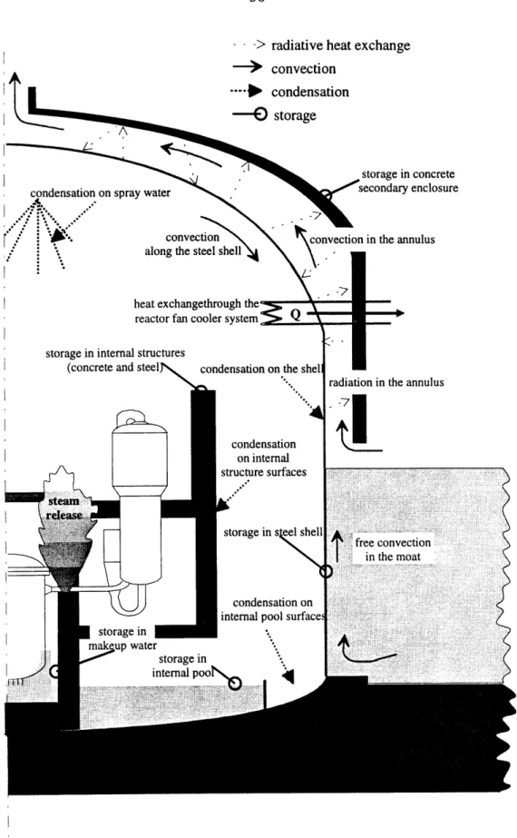
Figure 1.2 Heat removal mechanisms that limit the pressure excursion inside the containment following an accident
figure 1.1. Table 1.1 lists these heat rejection features. Figure 1.2 shows the horizontal cross section of the proposed containment. Note that only the compartments necessary for modeling purposes are included and that not all metal and concrete heat sinks within the containment are indicated. The important sinks are however included in the code modeling that was done for this project.
The heat rejection features that were incorporated into the proposed design are also indicated on figure 1.2, and so are the heat transfer mechanisms that limit the pressure excursion inside the containment. Following an accident, the features incorporated into the design aid in storing energy and in transferring heat to the environment.
Table 1.1 Heat Rejection Features Incorporated into the Proposed Containment
Feature Heat Removal Mechanism Computed LOCA
Heat Removal Rate at Peak Pressure(MW)
Air-convection annulus with * mixed convection 5.5 MW
chimney * radiation
External pool * free convection 29 MW
* subcooled nucleate boiling
*
saturated boilingInternal pools * energy storage 6 MW
*
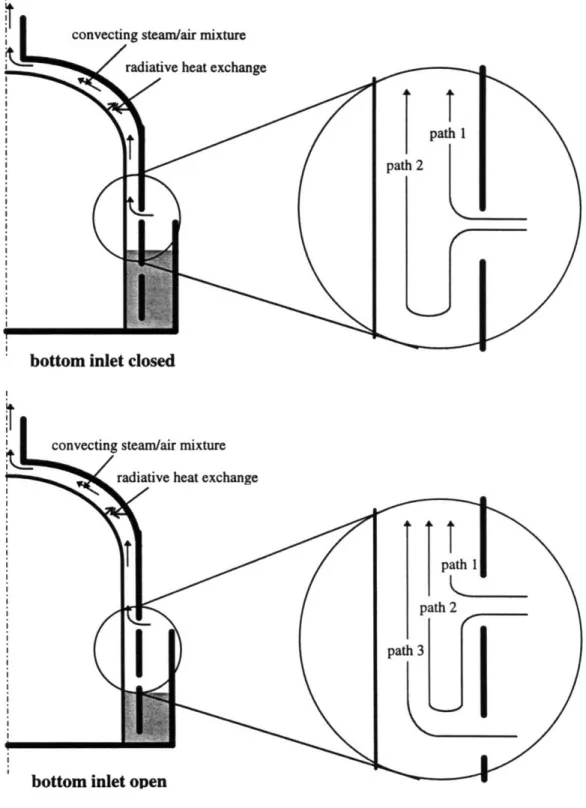
condensationThe upper portion of the shell is cooled by air convecting through the annulus that is formed between the shell and the secondary enclosure. The convection is enhanced because the annulus is equipped with a long chimney at the outlet, which contributes a
significant buoyancy driving force. Radiative heat exchange takes place between the containment shell and the secondary enclosure. The contribution of radiative heat exchange can be substantial during transients in which the shell temperature becomes very high; at the time of peak pressure and temperature in the containment, radiative heat exchange can be nearly 70 % of the total heat removal rate from the air-convection portion of the shell.
The lower half of the steel shell is in contact with a surrounding external pool. Heat transfer to the external pool can occur through several mechanisms. Two external pool configurations were evaluated during this study: a 0.5 m annular pool, and a large external moat. The annular pool operates in the free convection regime in the early stages of the transient when the water is still cold, then makes the transition to nucleate boiling as the pool water heats up, and can eventually reach complete saturated boiling conditions. While subcooled boiling and saturated boiling have higher heat transfer coefficients, the heat removal rate during free convection can be comparable to boiling because of the larger temperature difference between the wall and the pool water. For this reason, submersion of the shell in a large moat was also evaluated in the course of this project.
Another feature incorporated into the proposed design is an internal pool; the pool is contained in a cylindrical tank placed in the reactor cavity and sump region. The pool delays the increase in energy content of the containment atmosphere by storing energy in
the early stages of the transient. Another benefit of the internal pool is that it provides additional condensation surfaces and thus contributes to limiting the pressure rise inside the containment.
The cumulative effect of these features is to reject enough of the heat released during an accident to prevent the pressure in the containment from reaching design values during any design basis accident. These features thus eliminate the need to incorporate (or, at present, to rely upon) active features for the cooling of the containment. The active systems incorporated in currently operating reactors would however not be eliminated entirely. The reason for keeping some of these systems is that they have been designed for both normal and emergency operation. Specifically, in case of a primary system LOCA, water makeup is achieved by passive injection from accumulators and by active injection through designated systems and/or the residual heat removal system (RHRS). RHRS valves are realigned to recirculate water through the primary system after the refueling water storage tanks (RWSTs) are emptied. [The Westinghouse Pressurized Water Reactor Nuclear Power Plant, 1984]4 The recirculated coolant passes through the
RHRS heat exchangers, and energy is thus removed from inside the containment building to the condenser (which is outside the containment shell. This type of energy removal is not accounted for in any of the analyses performed for this project.
4 The RHRS is not used during emergency conditions in all operating reactors. Some PWRs use a
Furthermore, the pressure rise limitation due to the containment spray system activation is also not included in analyses for the proposed containment. The containment spray system not only condenses steam from the containment atmosphere, thus limiting the pressure rise, but it also serves to scrub radioactive fission products from the containment atmosphere. Given its scrubbing function, the containment spray is a desirable emergency system even if no credit is taken for its pressure limiting contribution.
Another heat rejection system included in the design of currently operating reactors is the reactor containment fan coolers system (RCFCS). The RCFCS is necessary during normal operations, but it is sized and qualified for its emergency function. The analyses performed for the proposed containment do not take credit for the 4 to 6 MWth heat removal capacity of the RCFCS. However, since this system provides the normal means of controlling the containment atmosphere temperature it must be kept even in passively cooled containments.
Table 1.2 lists the active systems that would not need to be qualified and sized for their emergency function if a passive containment is employed. Note that a coolant recirculation system (like the RHRS) still needs to be used under emergency conditions to maintain the core covered by replenishing water that is being lost through the break. However, the recirculation system would not have to remove heat from the reactor system.
It is worth noting again that some of these active systems cannot be eliminated from the design because of their normal operation functions. Also, keeping these systems as part of the design would allow operators to restore near ambient conditions faster if electric power remains available. However, there are cost benefits that result from not having to qualify these systems for their emergency function.
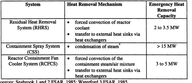
Table 1.2 Active Systems That do not Need to be Qualified for Emergency Functions in a PWR with a Passively Cooled Containment
System Heat Removal Mechanism Emergency Heat
Removal Capacity Residual Heat Removal * forced convection of reactor
System (RHRS) coolant 2 to 3.5 MW
* transfer to external heat sinks via heat exchangers
Containment Spray System * condensation of steam* > 15 MW (CSS)
Reactor Containment Fan * forced convection of the
Cooler System (RCFCS) containment steam/air mixture 3 to 5 MW * transfer to external heat sinks via
heat exchangers
Sources: Seabrook 1 and 2 FSAR, 1985; Waterford 3 FSAR, 1985
Note that the condensation of steam only limits the pressure rise at the time at which the spray is in effect. The spray water and the condensate will act as heat sources when and if they reach saturation conditions.
1.4 Available Analysis Tools
The primary criterion in the selection of a code is its ability to model every important phenomenon that affects the predicted results. In the case of a passively cooled containment, such as the one proposed in this work, all types of heat transfer mechanisms are important. There is conduction into heat sinks, through the steel shell primary enclosure and through the concrete secondary enclosure. There is convection inside the containment, in the annulus formed between the primary and the secondary enclosures, and in the external and internal pools. Radiation must be considered between the steel shell and the secondary enclosure. Phase change occurs both in the interior of the containment and outside. Inside the containment, there is condensation on the steel shell and on internal structures, as well as evaporation of water from the internal pools and the reactor cavity and sump. Water also evaporates from the external pool as energy is dumped into it through the containment. shell.
The above cursory description of heat transfer phenomena illustrates the complexity of phenomena that must be modeled to accurately assess the behavior of the containment. The conventional containment analysis codes are inadequate for long term transient analysis in a passively cooled reactor. These lumped parameter codes were developed to accurately handle natural phenomena only during the early stages of the transient, since after 30 seconds the active heat removal systems become operational. At that point, the bulk of the heat rejection occurs through these systems, and natural phenomena take a secondary role in pressure suppression. The lumped parameter codes have been refined
for years to include better condensation models. However, even the semi-empirical condensation correlations employed in these codes are sensitive to the flow along the wall. Consequently, the ability of the code to accurately model flow along the wall becomes very important. Lumped parameter codes only model flow among networked nodes. The nodes are connected through flow paths, which introduce a significant error in the computations. The error occurs due to the fact that flow junctions cannot transfer transverse momentum. This error is relatively small in a containment cooled by active systems since natural convection is not essential to heat rejection calculations. The error would however accumulate over the 72 hours during which heat transfer through the shell is essential in passively cooled containment analyses. Furthermore, for the proposed containment a more detailed knowledge of flow fields is required for an accurate estimate of the heat rejection because the main heat sink is located along the lower half on the outside of the containment shell. This makes it necessary to obtain an accurate estimate of the mixing inside the containment throughout the transient, which dictates the use of distributed parameter codes for passively cooled containment analyses.
There are several distributed parameter codes that have been adapted for containment analysis purposes (e.g., HMS, GASFLOW, COBRA-NC, GOTHIC). These 3-dimensional codes were developed specifically for containment applications. Some of these code have placed special emphasis on in-depth studies of specific aspects of containment analysis. Emphasis on specific phenomena often requires very fine meshing,
38
which makes the code less suitable to the modeling of an entire containment because of computational power limitations.
It is also possible to develop limited application codes that are only used for a particular part of the containment. Two such codes were developed at MIT (i.e., RECENT, and PREWAS) and used during this project. These codes focus on heat rejection through the steel shell. Specifically, they deal. with convection in the annulus and/or with heat rejection to the external pool. These codes can be designed to account for all the phenomena of interest in the specific region that they model, but they lose the important feed-back from in-containment behavior.
The code that was used to obtain comprehensive predictions for this project is the GOTHIC (Generation of Thermal-Hydraulic Information for Containments) Version 3.4e code. [George et al., 1991] The GOTHIC code was developed specifically for containment analyses, i.e., design, licensing, safety and operating analysis. The GOTHIC code was extensively verified and validated against experimental data collected specifically for containment applications. Throughout this project great care was taken to verify that the GOTHIC modeling employed for the proposed containment is suitable to each important phenomenon that needs to be considered. This meant that the containment models were successively refined, and also several changes in code logic were made to better fit this project's modeling needs. This aspect of the work became a significant portion of this project, since there are no precedents in the literature that show
how distributed parameter codes are to be used for a complete containment design. Moreover, in each containment, emphasis has to be placed on the accurate modeling of the specific phenomena that govern heat transfer in that containment, and thus a continual verification/modification of models becomes necessary in each case.
The pressure history shown in figure 1.3 was obtained using the GOTHIC code for the proposed containment in which a large break LOCA has occurred at time 0 of the transient. The GOTHIC code predictions, show that the proposed containment can reject sufficient heat to the environment so that containment pressures are maintained below design values. A further examination of the data obtained from GOTHIC runs shows that the remainder of the EPRI requirements for advanced reactor design that pertain to the containment are met.
The pressure history shows that a first pressure peak occurs within 20 seconds from the beginning of the transient. This first pressure peak is due to blowdown energy, i.e., energy stored within the coolant released by the blowdown), and occurs because neither storage nor rejection to the environment can limit the pressure rise in the very early stages of the transient. The pressure decreases after 20 seconds because storage within internal heat sinks removes energy from the containment atmosphere. The second pressure peak occurs at approximately 1,200 seconds (i.e., within less than 25 minutes from the beginning of the transient). This second peak is due to decay energy. The reduction in pressure after this second peak occurs because the large temperature difference between
40
the containment and the environment increases the heat rejection rate to the environment through both the air convection annulus and the external pool. The methods employed in
obtaining the above set of results are a large part of this thesis.
0.40 0.35 0.30 0.25 0.20 0.15 0.10
1.00E-01 1.00E+00 1.00E+01 1.00E+02 1.00E+03 1.00E+04
Time (s)
1.00E+05 1.00E+06
Figure 1.3 GOTHIC predicted 3 day pressure history in the proposed containment following a large break LOCA
- upper containment ... equipment room
12
Ii
-1.5 Organization of This Thesis
Chapter 2 provides an overview of passive containments that are being developed. These passive containments are classified according to their power rating. The important heat rejection features of these containments are discussed. Also included in chapter 2 is a discussion of experimental programs pertinent to passive containment development.
Chapter 3 covers the codes available for containment analysis, and describes the GOTHIC code and the modeling approaches used for the completion of this project. The succession of models used in reaching the final results is presented in detail.
Chapter 4 describes the features that have been incorporated in the proposed containment. The descriptions include preliminary calculations used to determine their efficacy, and GOTHIC code predictions of the performance of these features after they are integrated in the proposed containment. Chapter 5 elaborates on the performance of the large external moat, which is the most important heat rejection feature incorporated in the proposed design. The GOTHIC code predictions were verified by a set of experiments that confirm the effectiveness of the moat in removing heat from the containment.
Chapter 6 deals with the thermal-stratification expected to occur inside the containment. GOTHIC predictions are compared to a set of data obtained from a small scale experimental setup. The comparison led to a revision of the GOTHIC model to include a near-wall cell of the thickness of the boundary layer. Thermal stratification predictions
are particularly important in the analysis of the proposed containment because the main heat sinks are located at the bottom of the containment. If the model over-predicts mixing of the containment atmosphere, the heat rejection to the environment is over-predicted.
Chapter 7 describes the proposed containment and all the heat rejection features incorporated into the design. A detailed description of the GOTHIC models used for the final predictions is also included. Chapter 8 examines the behavior of the proposed containment during a large break LOCA and a main steam line break accident (MSLBA). The ability of hydrogen recombiners to mitigate the consequences of a large break LOCA accident that also involves the release of hydrogen because of core degradation is also discussed.
Chapter 9 concludes this work with a recapitulation of the main lessons learned during this research, and a series of suggestions for future work. Some of these suggestions pertain to further modifications that can be made to the proposed design to further increase its heat rejection ability. Recommendations are also made to modify analysis tools to better model some of the most important phenomena under consideration in passive containment design.