HAL Id: hal-03191559
https://hal.archives-ouvertes.fr/hal-03191559
Submitted on 7 Apr 2021HAL is a multi-disciplinary open access
archive for the deposit and dissemination of sci-entific research documents, whether they are pub-lished or not. The documents may come from teaching and research institutions in France or abroad, or from public or private research centers.
L’archive ouverte pluridisciplinaire HAL, est destinée au dépôt et à la diffusion de documents scientifiques de niveau recherche, publiés ou non, émanant des établissements d’enseignement et de recherche français ou étrangers, des laboratoires publics ou privés.
Pd(I) Phosphine Carbonyl and Hydride Complexes
Implicated in the Palladium-Catalyzed Oxo Process
Miguel Baya, Jennifer Houghton, Denes Konya, Yohan Champouret,
Jean-Claude Daran, Karina Q. Almeida Leñero, Lodewijk Schoon, Wilhelmus
P. Mul, A. Bart Van Oort, Nicolaas Meijboom, et al.
To cite this version:
Miguel Baya, Jennifer Houghton, Denes Konya, Yohan Champouret, Jean-Claude Daran, et al.. Pd(I) Phosphine Carbonyl and Hydride Complexes Implicated in the Palladium-Catalyzed Oxo Process. Journal of the American Chemical Society, American Chemical Society, 2008, 130 (32), pp.10612-10624. �10.1021/ja8012903�. �hal-03191559�
Pd(I) phosphine carbonyl and hydride complexes implicated in the
palladium-catalyzed oxo process
Miguel Baya,a† Jennifer Houghton,a Denes Konya,b Yohan Champouret,a Jean-Claude Daran,a Karina Q. Almeida Leñero,b Lodewijk Schoon,b Wilhelmus P. Mul,*b A. Bart van Oort,b
Nicolaas Meijboom,b Eite Drentb§ A. Guy Orpenc andRinaldo Poli*a
aLaboratoire de Chimie de Coordination, UPR CNRS 8241 liée par convention à l’Université
Paul Sabatier et à l’Institut National Polytechnique de Toulouse, 205 Route de Narbonne,
31077 Toulouse Cedex, France
bShell Global Solutions International B.V. Amsterdam, PO Box 38000, 1030 BN Amsterdam,
The Netherlands.
cSchool of Chemistry, University of Bristol, Cantock’s Close, Bristol, UK BS8 1TS.
Corresponding author: Rinaldo Poli, fax: +33-561553003, [email protected]
†Present address: Departamento de Química Inorgánica, Instituto de Ciencia de Materiales de
Aragón, Universidad de Zaragoza-CSIC, 50009 Zaragoza, Spain.
§Present address: Leiden Institute of Chemistry, Gorlaeus Laboratories, Leiden University,
Abstract
Reduction of compound “Pd(bcope)(OTf)2” [bcope = (c-C8H14-1,5)PCH2CH2P(c-C8H14-1,5);
OTf = O3SCF3], with H2/CO yields a mixture of Pd(I) compounds [Pd2(bcope)2(CO)2](OTf)2
(1) and [Pd2(bcope)2(-CO)(-H)](OTf) (2), whereas reduction with H2 or Ph3SiH in the
absence of CO leads to [Pd3(bcope)3(-H)2](OTf)2 (3). Exposure of 3 to CO leads to 1 and 2.
The structures of 1 and 3 have been determined by X-ray diffraction. Complex [Pd2(bcope)2
-(CO)2]2+ displays a metal-metal bonded structure with a square planar environment for the Pd
atoms and terminally bonded CO ligands and is fluxional in solution. DFT calculations aid the interpretation of this fluxional behaviour as resulting from an intramolecular exchange of the two inequivalent P atom positions via a symmetric bis-CO-bridged intermediate. A cyclic voltammetric investigation reveals a very complex redox behaviour for the “Pd(bcope)(OTf)2”/CO system and suggests possible pathways leading to the formation of the
various observed products, as well as their relationship with the active species of the PdL22+/CO/H2-catalyzed oxo processes (L2 = diphosphine ligands).
Introduction
Palladium catalysis is a cornerstone in organic synthesis and fine chemicals industry.1-3 The particular class of L2PdX2 derivatives, where L2 stands for a bidentate ligand (phosphine,
pyridine or thioether) and X represents a weakly or non-coordinating anion (most typically CF3SO3 = OTf, OTs or CF3CO2), has long been of interest to both academic and industrial
researchers as an efficient catalytic system for CO-olefin copolymerization.4-7 This catalytic system, however, has also been shown to perform other transformations such as the hydrocarbonylation of olefins to generate monomeric aldehydes, alcohols, ketones, or esters.8 The product selectivity critically depends on the basicity of the L2 ligand and on the acidity of
the HX reagent (the catalyst is usually prepared in situ from Pd(OAc)2, L2 and HX), as well as
on the amount of H2 used in the process. The general mechanism shown in Scheme 1, where
all metal species are positively charged, has been proposed for the reaction carried out in aprotic solvents such as diglyme, leading to saturated and unsaturated ketones by hydroacylation, to aldehydes and alcohols by hydroformylation with or without subsequent hydrogenation, or to polyketones by copolymerization.8 When the reactions are conducted in
methanol, esters, ketoesters and other compounds may also arise from methanolysis processes.5
R R R R R Pd H L L R Pd L L CO Pd L L O Pd O L L R -H R O H2 R R O nCO, n R R O n hydroacylation copolymerization H2 R O H H2 R CH2OH hydroformylation Scheme 1
More recently, it has been shown that this catalytic system, for the specific case of L2 =
(c-C8H14-1,5)PCH2CH2P(c-C8H14-1,5) (bcope), is also an efficient olefin isomerization
catalyst.9 This has allowed the optimization of experimental conditions leading to highly
selective transformations of internal olefins to linear alcohols by simultaneous isomerization – hydroformylation – hydrogenation in the presence of CO/H2 (syngas). In all cases, the key
catalytic intermediate is proposed to be a cationic three-coordinate Pd(II) hydride complex, [L2Pd(H)]+. This appears to be an extremely reactive intermediate and has never been
isolated or detected. A number of model systems have been studies in different groups using other ligands and olefins, 10-24 for which intermediates could be detected or sometimes isolated. However, while such model studies provide valuable information, the translation of these results to the “real” catalytic system is not straightforward. In this contribution, we report synthetic and electrochemical investigation of the [Pd(bcope)(OTf)2] pre-catalyst under
typical catalytic conditions, except for the absence of the olefin. The results that we have obtained provide, we believe, valuable new information on the nature of some of the
compounds that are involved in the catalytic cycle or off-loop species, while revealing the extreme complexity of palladium chemistry with this particular coordination environment under reducing conditions.
Results and Discussion
(a) Structural characterization of the starting material
Our study has started with the crystallization and structural characterization of the starting compound, “Pd(bcope)(OTf)2”. This is an air stable material and is used as a catalytic
precursor, thus its intimate structure is of interest. Single crystals grown from chloroform are monoclinic and display two independent [Pd(bcope)(H2O)2]2+ cations, four independent
TfO- anions and an additional interstitial H2O molecule in the asymmetric unit. Thus, the
compound should be described as [Pd(bcope)(H2O)2](OTf)2∙H2O. Given that an anhydrous
solvent was used for the crystallization, we deduce that the compound is probably hygroscopic and incorporates water when kept in moist air.25 The Pd complex shows the
expected square planar configuration with two cis positions occupied by the chelating bcope ligand and the remaining ones filled by aqua ligands, see Figure 1. The H2O ligands are
connected to the triflate counterions and to the interstitial water molecule by H-bonding, building an intricate network. Selected bond distances and angles are collected in Table 1, whereas significant H-bonding contacts are reported as Supporting Information. The structure of a methanol solvate of the same compound, [Pd(bcope)(MeOH)2](OTf)2∙2MeOH,
Figure 1. ORTEP view of one of the two independent dications in compound
[Pd(bcope)(H2O)2](OTf)2∙H2O. Ellipsoids are drawn at the 50% probability level
and H atoms are not shown for clarity.
Table 1. Selected bond distances (Å) and angles (°) for complex [Pd(bcope)(H2O)2]2+.
Distances Pd1-P1 2.2393(11) Pd2-P3 2.2422(11) Pd1-P2 2.2407(11) Pd2-P4 2.2427(11) Pd1-O1 2.154(3) Pd2-O3 2.129(3) Pd1-O2 2.127(3) Pd2-O4 2.150(3) Angles P1-Pd1-P2 84.20(4) P3-Pd2-P4 84.14(4) P1-Pd1-O1 170.47(9) P3-Pd2-O3 175.67(9) P1-Pd1-O2 97.23(9) P3-Pd2-O4 95.52(9) P2-Pd1-O1 95.95(9) P4-Pd2-O3 97.45(8) P2-Pd1-O2 175.56(10) P4-Pd2-O4 170.19(9) O1-Pd1-O2 83.33(12) O3-Pd2-O4 83.60(11) (b) Syntheses
The reduction of [Pd(bcope)(H2O)2](OTf)2 under a 1:1 CO/H2 mixture (syngas)
proceeds smoothly, yielding a mixture of two products: a dinuclear Pd(I) carbonyl product, [Pd2(bcope)2(CO)2](OTf)2, 1, and a mixed hydrido carbonyl derivative,
[(bcope)Pd(-CO)(-H)Pd(bcope)](OTf), 2, see Scheme 2. We presume that the metal is reduced by H2 to yield
triflic acid, since no reaction occurs upon exposure to a neat CO atmosphere. This contrasts with the reported reduction of [Pd(dppm)(OTf)2] by CO in the presence of water, which yields
depending on the amount of CO.26 The greater assembling power and/or poorer donating
ability of dppm relative to bcope may be responsible for this difference.
In addition, the reduction of the analogous [Pd(dppp)(OTf)2] compound by H2 was
previously reported to yield [Pd2(dppp)2](OTf)2.27 The stoichiometry of the reaction leading
to the dicarbonyl product is shown in Equation 1, whereas that leading to the hydrido-bridged product is in Equation 2. The hydrido-bridged cation 2 is related to the previously reported [Pd2(dippp)2(-CO)(-H)]+ complex [dippp = iPr2P(CH2)3PiPr2].28 The stoichiometry of the
dicarbonyl product, on the other hand, is unprecedented. Although not fully mapped, the ratio
1/2 may depend on variables like solvent, pressure, reaction time and initial concentration of
the precursor, as shown by IR and NMR monitoring.
P Pd P OH2 OH2 P P = 2+ P P CO, H2 P Pd P CO P Pd P CO 2+ + P Pd P O C H P Pd P + -H2O 1 2 (OTf )2 (OTf ) 2 OTf -Scheme 2 2 [Pd(bcope)(H2O)2](OTf)2 + 2 CO + H2
[Pd2(bcope)2(CO)2](OTf)2 + 2 TfOH + 4 H2O
Equation 1
Equation 2
The reaction of “Pd(bcope)(OTf)2” with syngas in CD3OD was monitored at room
temperature by 1H and 31P NMR spectroscopy by means of a tube equipped with a Young tap
fitting. At 1 bar, the colour changed immediately from yellow to orange while conversion to the dicarbonyl complex slowly took place (3% after 8 min, 10% after 40 min). After raising the pressure to 1.35 bars, the formation of the hydrido carbonyl product could also be observed (9% after 5 min). Evidently, as suggested by the different stoichiometry, the hydrido compound should be favoured by a greater H2 pressure. At the same time, the
dicarbonyl product started to precipitate while the color darkened to red-brown and the starting material was completely consumed after 35 min. When this product mixture was further exposed to an atmosphere of pure H2, the relative amount of hydrido-carbonyl product
increased and some of the precipitate redissolved, suggesting that the two products are able to interconvert under these conditions (Equation 3). Using “SWET” as a solvent,29 1 and 2 are
formed in a ratio of about 3:2 under 30 bar H2/CO (1:1) at r.t., while upon increasing the
temperature to 103 C, this ratio is shifted to about 1:4. Upon removal of syngas, the parent compound “Pd(bcope)(OTf)2” is reformed again, albeit slowly (taking a few days at r.t.).
[Pd2(bcope)2(CO)2](OTf)2 + H2 [Pd2(bcope)2(-CO)(-H)](OTf) + CO + TfOH
Equation 3
When the starting material “Pd(bcope)(OTf)2” was exposed to H2 in the absence of CO,
on the other hand, a different compound, [Pd3(bcope)3(H)2](OTf)2 (3), was obtained
selectively and quantitatively, see Scheme 3. The stoichiometry of this reaction is presumed to be as shown in Equation 4. Silanes are also able to yield this trinuclear species, Me2PhSiH
presumably as shown in Equation 5, the H2 by-product resulting from the neutralization of
one equivalent of TfOH with the 4th equivalent of silane. The stoichiometry of this product is apparently unprecedented for palladium. The reduction of other Pd phosphine precursors has been reported to lead to different stoichiometries. As mentioned above, the reduction of [Pd(dppp)(OTf)2] yields [Pd2(dppp)2](OTf)2.27 The reduction of Pd(dippp)I2 by KBEt3H
affords Pd2(dippp)2(-H)2,30 whereas the reduction of Pd2Cl2(dppm)2 by NaBH431 leads to a
product formulated as [Pd4(dppm)4(-H)2]2+.32, 33 It seems that the nature of the reduced
hydride product is highly phosphine dependent. Only one other hydride derivative of a triangular Pd3 cluster, [Pd3(dppm)3(3-CO)(3-H)]+, has been described quite recently.34 A
dication having the same stoichiometry as the presently described [Pd3(bcope)3(H)2]2+ cluster
is known for platinum, [Pt3(dppm)3(H)2]2+, although it was not structurally characterized.35, 36
P Pd P OH2 OH2 2+ P Pd P H P Pd P H 2+ -H2O 3 (OTf-)2 (OTf-)2 H2 Pd P P -TfOH Scheme 3 3 [Pd(bcope)(H2O)2](OTf)2 + 3 H2
[Pd3(bcope)3(-H)2](OTf)2 + 4 TfOH + 6 H2O
Equation 4
3 [Pd(bcope)(H2O)2](OTf)2 + 4 PhMe2SiH
[Pd3(bcope)3(-H)2](OTf)2 + 4 TfOSiMe2Ph + H2 + 6 H2O
Interestingly, the trinuclear product also forms on gradually warming “Pd(bcope)(OTf)2” in the presence of methanol or ethanol, albeit slowly (few % after several
hours at 75°C). The alcohol is presumably acting as reducing agent in this case, according to the hypothetical mechanism shown in Scheme 4 (for EtOH). According to this mechanism, conversion of “Pd(bcope)(OTf)2” to compound 3 is expected to occur with any higher primary
and secondary aliphatic alcohol. When exposed to a CO atmosphere (2 bar), complex 3 reacts to form a mixture of 1 (minor) and 2 (major). This procedure allowed the recovery, after crystallization of the less soluble 1, of the hydrido carbonyl product in a relatively pure form (according to the NMR).
3 [Pd(bcope)(OH2)2](OTf)2 +3 EtOH
3 [Pd(bcope)(EtOH)(H2O)](OTf)2 + 3 H2O
3 [Pd(bcope)(EtOH)(H2O)](OTf)2 3 [Pd(bcope)(OEt)(H2O)](OTf) + 3 TfOH
3 [Pd(bcope)(OEt)(H2O)](OTf) 3 [Pd(bcope)H(H2O)](OTf) + 3 CH3CHO
3 [Pd(bcope)H(H2O)](OTf) [Pd3(bcope)3(-H)2](OTf)2 + TfOH + 3 H2O
Scheme 4
(c) Spectroscopic characterization
The IR spectrum of compound 1 in the CO stretching region shows two bands at 2084 and 2066 cm-1 in CH2Cl2, indicating that the CO ligands are terminally bonded to the Pd
centres. No bands are observed in the region typical of bridging CO ligands above the noise level. The Pd(I) product is stable under CO, but its solutions change color from yellow to orange and then red if kept without a protecting CO atmosphere. Contemporarily, new broad resonances at 28 and 32 (in CD2Cl2) develop in the 31P NMR spectrum and the CO
stretching bands completely disappear, without being replaced by any new band. The solution color changes back to yellow and these new resonances disappear when CO is bubbled
through the solution, indicating the occurrence of a reversible CO dissociation. The freshly prepared solid is yellow if isolated as a powder, and darkened to orange as a function of storage time when kept under Ar. However, well-formed crystals are red. The product(s) of this CO dissociation is(are) CO-free, possibly related to the above-mentioned [Pd2(dppp)2](OTf)2.27 No attempts were made to isolate or further investigate this(ese)
product(s).
The 31P NMR spectrum of [Pd2(bcope)2(CO)2]2+ shows a single resonance at 50.0 in
CD2Cl2 at room temperature, which decoalesces upon cooling, yielding two resonances in a
1:1 ratio at low temperatures (Figure 2). This is indicative of signal averaging because of the rapid exchange of two inequivalent positions. No P-P coupling could be discerned at the lowest temperature reached in this study. A slight upfield shift is also observed upon cooling. The possible intervention of a temperature dependent equilibrium between two isomers (i.e. with terminal and bridging CO, vide infra) seems excluded by the absence of characteristic IR absorptions for bridging CO ligands, as mentioned above. The lineshape analysis (excluding the lowest temperature spectrum, which is artificially broadened by the increased solvent viscosity near the freezing point) yields the activation parameters for the exchange processH‡ = 9.9±0.7 kcal mol-1 and S‡ = -5±3 cal mol-1 K-1. The asymmetric coordination mode for the bcope ligand is confirmed by the X-ray analysis, vide infra.
44 46 48 50 52 54 /ppm T = 298 K 273 K 253 K 233 K 213 K 193 K
Figure 2. Variable temperature 31P{1H} NMR spectrum of [Pd2(bcope)2(CO)2](OTf)2 in
CD2Cl2.
The spectroscopic properties of compound 2 compare quite closely with those of the previously reported [Pd2(dippp)2(-CO)(-H)]+ analogue.28 Particularly diagnostic is the 1H
resonance of the bridging hydride ligand at -5.50 in CD2Cl2 (quintet for 1 H with JHP = 46.9
Hz), whereas that of the literature analogue is at -5.17 (in CD3OD, JHP = 41.1 Hz) and the
stretching vibration of the bridging carbonyl ligand at 1818 cm-1, vs. 1789 cm-1 for the literature analogue.
Compound 3 is characterized by a single hydride resonance at -6.53 in CD2Cl2,
integrating to two H atoms and split into a septet by 6 equivalent P nuclei (JPH = 36.9 Hz).
This indicates that the hydride ligands are equivalent and occupy highly symmetric positions, as suggested in Scheme 3. The P nuclei afford a single 31P NMR resonance at 52.7. Although the spectroscopic properties do not exclude the existence of a dynamic exchange process for a less symmetric structure, the more symmetric geometry is supported by the crystallographic investigation (next section).
(d) Crystallographic analyses
Single crystals of compound 1 were grown from a MeOH/Et2O mixture. The geometry
of the dinuclear dication, shown in Figure 3, reveals an unbridged metal-metal bond with a Pd-Pd distance of 2.6085(4) Å. The coordination geometry around each Pd center is close to ideal square planar, the chelating bcope ligand being arranged asymmetrically with one P donor atom trans to the CO ligand and the other one trans to the second Pd atom. The two square planes are twisted around the Pd-Pd bond by a dihedral angle close to 90°, probably resulting from the ligand-ligand steric repulsion and the absence of Pd-Pd bonding. Selected bond distances and angles are collected in Table 2. It is of interest to note that the Pd-P bonds trans to the Pd-Pd bond (P1, P4) are longer than those trans to CO ligands (P2, P3), indicating that the Pd-Pd bond exerts a stronger trans influence than the CO ligand. This trend is reproduced by the DFT geometry optimization (vide infra). The Pd-P bond lengths in this complex are longer than those in the [Pd(bcope)(H2O)2]2+ complex, as expected from the
lower formal oxidation state and the stronger trans influence exerted by the CO ligand and by the Pd-Pd bond.
Figure 3. ORTEP view of the dication in compound [Pd2(bcope)2(CO)2](OTf)2. Ellipsoids
Table 2. Selected bond distances (Å) and angles (°) for complex [Pd2(LL)2(CO)2]2+
(experimental X-ray determination: LL = bcope; DFT calculation: LL = DHPE).
Terminal CO TS Bridging CO X-ray DFT DFT DFT Distances Pd1-Pd2 2.6085(4) 2.666 2.830 2.836 Pd1-P1 2.3407(11) 2.436 2.409 2.422 Pd2-P4 2.3412(11) Pd1-P2 2.3300(11) 2.361 2.410 2.422 Pd2-P3 2.3179(11) Pd1-C1 1.926(5) 1.971 1.979 2.110 Pd2-C2 1.937(5) Pd1-C2 2.720(5) 3.113 2.417 2.110 Pd2-C1 2.896(4) C1-O1 1.115(6) 1.136 1.149 1.156 C2-O2 1.123(6) Angles Pd2-Pd1-P1 176.71(3) 175.9 154.0 138.4 Pd1-Pd2-P4 174.07(3) Pd2-Pd1-P2 97.20(3) 92.3 120.8 138.4 Pd1-Pd2-P3 101.33(3) Pd2-Pd1-C1 77.78(13) 83.0 57.1 47.8 Pd1-Pd2-C2 71.78(14) P1-Pd1-P2 85.94(4) 83.9 83.6 83.3 P3-Pd2-P4 83.81(4) P1-Pd1-C1 99.09(13) 100.8 97.7 90.6 P4-Pd2-C2 102.85(14) P2-Pd1-C1 174.97(13) 175.0 174.6 173.8 P3-Pd2-C2 171.80(14) Pd1-C1-O1 173.3(4) 177.5 155.8 137.7 Pd2-C2-O2 172.8(4) Pd-C-Pd - - 79.5 84.5 Dihedral angle C-Pd-Pd-C 98.3(2) 94.7 140.9 180.0
According to the Cambridge Structural Database, this is the first structural determination for a Pd(I) complex containing only phosphine and carbonyl ligands. The structure is closely related to those of other unbridged dicationic PdI complexes such as [Pd2(PMe3)6]2+ and [Pd2(LL)2(L')2]2+ LL = diphosphine; L’ = isocyanide).37-40 The dihedral
angle between the two square planes in these compounds is also close to 90°. Other related compounds are [Pd2(PPh2CH=CH2)2(-PPh2CH=CH2)2]2+,41 [Pd2{-2,6-NC5H3(PPh2)2}2]2+,42
[Pd2(-Ph2PNHPPh2)2(PPh3)2]2+,43 and [Pd2(-PR2CH2CH2P(Ph)CH2CH2PR2)2]2+ (R = Et,
Ph),44 where the presence of bridging ligands forces coplanarity. In the structure of the
above-mentioned [Pd2(dppp)2](OTf)2,27 coplanarity appears to be imposed by a Pd-(-arene)
interaction.45 The closest dinuclear carbonylpalladium(I) systems appear to be the cationic complexes [Pd2(LL)2(-CO)(X)]+ (X = H, L = dippp28; X = CH3, L = dippe46), where CO
adopts, however, a bridging coordination mode. The isoelectronic neutral dihydride complex [Pd2(dippp)2(-H)2] also adopts a bridged structure.30 Complex [Pd2(dppp)2]2+ was shown to
react with CO to yield [Pd2(dppp)2(CO)2]2+, but this was only characterized in solution and
described as having a probable bis(CO)-bridged structure, although the possibility for a fluctional unbridged structure, similar to that revealed spectroscopically for [Pd2(dppp)2(MeCN)2]2+, was also advanced.27 The only other crystallographically
characterized compounds containing only phosphine and CO ligands are the dinuclear Pd20
complex [Pd2(tBu2PCH2CH2PtBu2)2(-CO)],47 a variety of higher nuclearity clusters,48-51 and
the mixed-valence Pd30,I,I cluster [Pd3(dmpe)3(3-CO)]2+.52-55
The comparison of the above structures brings us to consider the aptitude of the CO ligand to bind a Pd center in a terminal fashion vs. bridging two or three Pd centres (e.g. I vs.
II vs. III). The bridging aptitude of carbon monoxide is stronger than that of the isoelectronic
isocyanide ligand, and it is favoured by a greater electron density on the metal centre. This property is nicely illustrated by the unfailing presence of bridging CO (type II or III) in Pd0 carbonyl clusters. Mixed-valence Pd30,I,Icomplexes also feature a bridging coordination mode
(type III). For the PdI species, the bridging mode (type II) is again observed for the neutral [Pd(-CO)(-O2CCH3)]4 complex56 and for the monocationic [Pd2(dppb)2(-CO)(X)]+ (X =
H, CH3) complexes.28, 46 However, going to the dicationic [Pd2(bcope)2(CO)2]2+ tilts the
C Pd O C Pd O Pd C Pd O Pd Pd I II III
Well formed crystals of compound [Pd3(bcope)3(H)2](OTf)2 (3) as a methanol solvate
were obtained and analyzed by X-ray diffraction. This crystal structure displays two independent dications in the asymmetric unit, only one of which is ordered. The second one is severely disordered (see details in the Experimental section). The structure determination, however, is sufficiently well developed to unambiguously identify the cluster geometry as shown in Scheme 3. A view of the ordered cluster is shown in Figure 4. Both independent dications sit on crystallographic threefold axes, therefore the Pd3 triangle is perfectly
equilateral. The three Pd(bcope) units are arranged in propeller fashion with exact C3 and
near-D3 symmetry, with the P2Pd planes being skewed relative to the Pd3 plane by 46.00(8)°
for the ordered cluster and 46.7(2)° for the disordered one. The hydride ligands were not located but presumably triply bridge the Pd3 triangle. Note that the diphosphine ligands adopt
a chelating mode in cluster 3, whereas the many crystallographically characterized Pd3(LL)3
and Pt3(LL)3 systems with LL = dppm display a bridging mode for the smaller bite
diphosphinomethane ligand.52-55, 57-64 In the structure of the somewhat related
[Pt3(dppe)3(H)3]+, the diphosphine also adopts a chelating mode.65 As mentioned above, a Pt
complex having the same stoichiometry, [Pt3(dppe)3(H)2]2+, has previously been reported but
not structurally characterized.35, 36 A related derivative for which an X-ray structure has been determined is [Pt3(dppm)3(H){P(OMe)3}]+.66, 67
Figure 4. ORTEP view of the ordered trinuclear [Pd3(bcope)3H2]2+ cluster in compound 3.
Ellipsoids are drawn at the 30% probability level and H atoms are not shown for clarity. Important bond distances (Å) and angles (°): Pd1-Pd1i, 2.8280(12);
Pd1-P1, 2.267(3); Pd1-P2, 2.340(3); P1-Pd1-P2, 86.85(11). The corresponding values for the disordered dication are: Pd2-Pd2i, 2.800(5); Pd2-P3, 2.310(7); Pd2-P4, 2.296(8); P3-Pd3-P4, 87.2(3).
(e) DFT calculations
The P exchange process observed in complex [Pd2(bcope)2(CO)2]2+ was further probed
by a DFT calculation on the model system where the simpler H2PCH2CH2PH2 (DHPE) ligand
replaces the bcope ligand. The results are summarized in Figure 5 and the DFT optimized bond distances and angles are compared with the experimental data in Table 2. The experimental geometry revealed by the crystallographic study corresponds indeed very closely to the global energy minimum. The obvious symmetric structure allowing the P exchange is one where the CO ligands rearrange from a terminal to a bridging position, similar to the structure experimentally observed for [Pd2(dppb)2(-CO)(-H)]+ and
see Figure 5. The transition state leading from the terminal to the bridging CO structure was also optimized. It resides 6.1 kcal mol-1 higher than the global minimum and 2.3 kcal mol-1 higher than the intermediate CO-bridged structure. These results are in rather good agreement with the low P exchange barrier (H‡ = 9.9±0.7 kcal mol-1) shown by the NMR study and with the absence of a significant equilibrium population of the CO-bridged structure. Thus, it would appear that the preference for a terminal CO binding mode (I) relative to a bridging one (II) depends on the compound charge, as discussed above, and not on the chelating ligand nature. The square planar coordination sphere is little perturbed by the rearrangement, as signalled by the minor variation of the P1-Pd-P2 and P1-Pd-CO angles. The isomerization mostly involves an electronic rearrangement in the Pd2(CO)2 moiety, as shown by the
lengthening of the Pd-Pd, Pd-C and C-O distances on going from the terminal to the bridged structure.
Figure 5. DFT optimized structures and relative energies of [Pd2(DHPE)2(CO)2]2+.
(f) Electrochemical studies
In order to learn more on the reduction mechanism leading to the formation of the Pd(I) complex [Pd2(bcope)2(CO)2]2+, the PdII compound [Pd(bcope)(H2O)2]2+ was studied by cyclic
voltammetry in CH2Cl2 solution, both under Ar and under CO. The complete study was
carbon), yielding identical results. The studies were carried out with three different supporting electrolytes: nBu4NPF6 (TBAPF6), nBu4NO3SCF3 (TBAOTf), and
nBu4N[B{C6H3(CF3)2-3,5}4] (TBABArF). This was necessary because our initial studies
using the more common TBAPF6 indicated a complex behavior, attributed to ion pairing
phenomena. As it has been recently shown,68-70 the use of bulkier anions in the supporting electrolyte, especially fluorinated tetraarylborates, greatly simplifies the response of electro-chemical processes involving successive oxidation steps. Given the charge/size ratio, the ion paring of the above salts in CH2Cl2 follows the order TBAPF6 > TBAOTf > TBABArF.
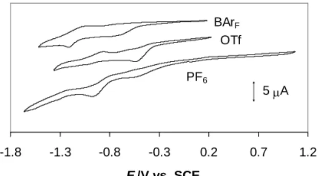
The redox behavior is not well defined under Ar. Two reduction processes are visible at ca. -0.55 and -1.0 V in the presence of the TBAPF6 and TBAOTf supporting electrolytes but
their relative intensity is different on going from one salt to the other one. Both processes are shifted to more negative potentials in the presence of the TBABArF salt, see Figure 6. No
electrochemical activity until the solvent discharge was observed in oxidative scans, consistent with the stability of square planar PdII toward oxidation. A more detailed analysis
of these reductive processes by multiple scans and variable scan rates did not allow us to extract a clear picture of the chemical processes that are associated with the electrochemical reductions. The compound most likely decomposes to unstable products following its reduction, since there are no ligands capable to effectively stabilize the resulting lower oxidation state palladium center. Thus, a dinuclear [Pd2(bcope)2]2+ complex similar to
[Pd2(dppp)2]2+ does not appear to be stable, presumably because bcope does not have aryl
substituents to occupy the vacant site as in the dppp complex.27 This difference could also
explain the formation of compound 3 upon reduction with H2, whereas [Pd(dppp)(OTf)2]
-1.8 -1.3 -0.8 -0.3 0.2 0.7 1.2 E /V vs. SCE 5 A PF6 OTf BArF
Figure 6. Cyclic voltammograms of Pd(bcope)(OTf)2 in CH2Cl2 (C = 3.5·10-3 M) under
argon, in the presence of different nBu4N+ salts as supporting electrolytes (0.1 M).
The scan rate is 100 mV s-1.
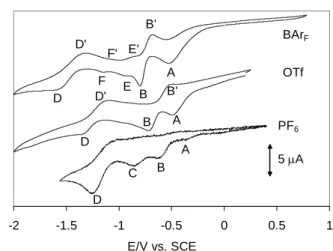
After placing the samples under a CO atmosphere, much better defined electrochemical responses were obtained. A preliminary investigation with reductive scans yields the voltammograms shown in Figure 7. Again, no electrochemical activity was observed during the oxidative scans. As can be appreciated from the Figure, the electrochemical behavior is highly dependent on the nature of the supporting electrolyte, indicating a strong influence of ion pairing effects. The first important observation concerns the potential of the first irreversible peak A, which is ca. -0.36 V for PF6, -0.49 V for OTf and -0.52 V for BArF, and
corresponds quite closely to the first reduction process observed under Ar. This is consistent with the absence of a chemical interaction between CO and the PdII complex, which is also indicated by the absence of any observable change (color and spectroscopic properties) upon exposing the [Pd(bcope)(H2O)2]2+ solution to a CO atmosphere. Thus, peak A can be
attributed to the reduction of mononuclear PdII to PdI. The monoelectronic nature of this
Figure 7. Cyclic voltammograms of Pd(bcope)(OTf)2 under CO. The other conditions are
identical to those in Figure 6.
The first reduction peak is followed by a second one, B, whose position is also strongly anion-dependent (-0.62 V for PF6, -0.71 V for OTf and -0.80 V for BArF). An oxidation wave B' is also present, the position and relative intensity of which are quite strongly
electrolyte-dependent (not discernible for PF6, ca -0.5 V with intermediate intensity for OTf, ca. -0.68 V
for BArF). As will be shown later, this process is not associated to the reduction wave B. At
more negative potentials, two distinct reductive peaks C (ca. -0.86 V) and D (ca. -1.25 V), corresponding to irreversible processes, are clearly visible for the PF6 solution. For the other
two solutions, peak D appears to be still present, though at smaller intensity and at lower potential (ca. -1.34 V for OTf and ca. -1.55 V for BArF), whereas peak C is not visible. An
oxidation process D' is more clearly visible for the OTf and BArF solutions. On the other
hand, two additional and reversible processes E/E' (ca. -0.90) and F/F' (ca. -1.10) become visible for the BArF solution. The first one is also visible in the OTf solution under certain
conditions (vide infra).
The results obtained with the PF6 supporting electrolyte are quite complex. The
observed behavior very much depends on the electrode history with certain bands appearing or disappearing after polishing. Therefore, for the sake of simplicity, we shall examine and
-2 -1.5 -1 -0.5 0 0.5 1 E/V vs. SCE 5 A OTf BArF B A B B E F D D B' B' D' D' PF6 D C A A E' F'
discuss in more detail only the results obtained with the OTf and BArF salts, with occasional
mention of the corresponding behavior in the presence of the PF6 salt. All voltammograms
that will be presented and discussed have been obtained on a freshly polished working electrode (see Experimental section).
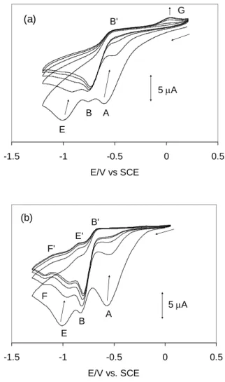
It is useful to first examine the voltammetric response for a fast (1000 mV/s), multiple scan experiment, shown in Figure 8. The behavior is nearly identical in the presence of the OTf and BArF electrolytes. The first scan shows the prominence of peak A, followed by peak B with a relatively small intensity, and by peak E with an intensity similar to that of A. The
EC value, like the EA value and unlike the EB value, is essentially identical in the presence of
the two different supporting electrolytes (ca. -1.01 V at this scan rate). In subsequent scans, peaks A and E drastically decrease in intensity while peak B remains approximately unchanged. Note also that both peaks A and E shift to less negative potentials as their intensity decreases, indicating concentration dependence for the cathodic peak potential. Peaks A and E essentially disappear after the 3rd scan for the OTf solution, whereas they remain at small intensity at dynamic equilibrium (> 5th scan) for the BArF solution. For the
corresponding PF6 solution, peak A is visible (with a relatively small intensity) only during
the first scan. At the same time, an anodic peak (G) develops at ca. +0.04 V, but remains small at dynamic equilibrium and is visible only for the OTf and PF6 solutions. Peak F is also
visible at dynamic equilibrium, but only for the BArF solution, with a similar intensity to E.
However, contrary to E, it is not observed during the first scan. This means that the species responsible for F is not a primary product of the electrochemical reduction. It is probably a species derived from either an irreversible or a reversible (equilibrium) transformation of a primary reduction product. Note also that both processes leading to E and F appear electro-chemically reversible at this scan rate, since their return peaks E' and F' are also clearly visible.
-1.5 -1 -0.5 0 0.5 E/V vs SCE 5 A A B E B' G (a) -1.5 -1 -0.5 0 0.5 E/V vs. SCE A B E B' F E' F' 5 A (b)
Figure 8. Five-scan cyclic voltammogram of Pd(bcope)(OTf)2 in CH2Cl2 under CO at 1000
mV s-1. Electrolyte: OTf (a), BAr
F (b). Other conditions are identical to Figure 6.
A first assignment of the main chemical processes is possible on the basis of a few parallel coulometric and cyclic voltammetric studies. Bulk reductive electrolysis under a CO atmosphere of a solution of Pd(bcope)(OTf)2 containing the TBAOTf electrolyte at a constant
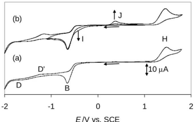
potential of -0.5 V consumed 1.0 electrons per Pd atom, while the color of the solution did not significantly change. After electrolysis, the solution exhibited the cyclic voltammogram shown in Figure 9. Since the consumption of 1 electron per Pd atom strongly indicated the formation of complex [Pd2(bcope)2(CO)2]2+, a genuine sample of this compound was also
electron and leads to the formation of the dinuclear PdI carbonyl compound, according to the stoichiometry of Equation 6. -2 -1 0 1 2 E /V vs. SCE B H J I D D' 10 A (a) (b)
Figure 9. Cyclic voltammogram of a solution obtained upon extensive electrolysis of
Pd(bcope)(OTf)2 in CH2Cl2 under CO at -0.5 V (electrolyte: 0.1 M TBAOTf).
Scan rate = 100 mV/s. (a) Recorded with a freshly polished electrode. (b) Two consecutive scans recorded after scan (a).
2 [Pd(bcope)]2+ + 2 CO + 2 e- [Pd2(bcope)2(CO)2]2+
Equation 6
The voltammogram of complex [Pd2(bcope)2(CO)2]2+ is rather simple when recorded
with a freshly polished electrode (Figure 9a), showing two irreversible peaks, a cathodic one with Ep,c = ca. -0.66 V (B) and an anodic one with Ep,a = ca. +1.50 V (H), plus small features
corresponding to D and D'. The shape of the voltammogram is the same whether the scan starts in the anodic or in the cathodic direction, showing that both B and H are primary electrochemical processes of compound [Pd2(bcope)2(CO)2]2+. On the other hand,
consecutive scans reveal the development of two new features – a cathodic process at ca. -0.40 V (shoulder I of peak B) and an anodic one at ca. +0.40 V (peak J) – while at the same time the D and D' features also increased (Figure 9b). Since subsequent electrode polishing restores the voltammogram shown in Figure 9a, peaks D, D', I and J are attributed to
processes involving the participation of reduced Pd species that deposit on the electrode surface following the reductive process B. At this point, it is useful to comment on the catalytic performance of the Pd(OAc)2/L2/HX system in olefin/CO copolymerization and on
the need to add oxidants such as benzoquinone in order to improve catalytic performance. The interpretation of this phenomenon is that the active palladium catalyst can “drop out” by decomposition to Pd0.5 Our electrochemical experiment shows that indeed reduced species
deposit on the electron surface, but only upon reducing beyond the oxidation state +1. Carbon monoxide coordination stabilizes the PdI product, so that this is not removed as a catalyst from the system and indeed, as shown above (Equation 3) it can be reconverted into a hydride complex upon exposure to H2.
We have further carried out a coulometric reduction experiment on the isolated [Pd2(bcope)2(CO)2]2+, for which we measured the consumption of ca. 1.3 electrons per
dinuclear complex and have measured the cyclic voltammetry of the resulting solution. However, we have not succeeded in isolating this reduction product. The reduction stoichiometry indicates that complex rearrangements follow the reduction at B and excludes the direct formation of a dinuclear Pd0 product which might lose ligand and precipitate. Thus,
the formation of a solid deposit on the electrode must be the result of further reduction of this product. Clearly, the reductive behaviour of “Pd(bcope)(OTf)2” under CO is quite complex.
We did not pursue the investigation of these deep reduction products, nor of the insoluble material deposited on the electrode.
On the basis of the above coulometric and cyclic voltammetric experiments, a first mechanistic interpretation can be deduced as shown in Scheme 5. The PdII precursor does not interact with CO. After monoelectronic reduction at A, CO rapidly replaces the aqua ligands to yield a 1:1 adduct [PdI(bcope)(CO)]+, which is then reduced further at E by a 1-electron process, to yield mononuclear Pd0(bcope)(CO). The equivalence of EE in the
presence of the two OTf and BArF salts indicates a negligible ion pairing effect for the
reduction of [PdI(bcope)(CO)]+. At competitive rates, however, the mononuclear PdI complex dimerizes to yield [PdI2(bcope)2(CO)2]2+, which is reduced at EB. The dependence
of EB on the nature of the supporting electrolyte indicates stronger ion pairing for the
dinuclear species, in line with its higher positive charge. Note that EB > EE, showing that
dimerization facilitates the reduction process. The rapid disappearance of peak A in the fast, multiple scan experiment (Figure 8) indicates that the precursor PdII complex is being consumed by a chemical process involving its own reduction products generated in the diffusion layer. Among the two possibilities (product of process B and product of process E), only the former one agrees with the data. In fact, a depletion phenomenon is also observed when the multiple scan is carried out by reversing the scan at -0.9 V, immediately after process B, although the relative proximity of the E process does not make this evidence unambiguous. However, process E/E' shows electrochemical reversibility at dynamic equilibrium, excluding that the Pd0 product is engaged in a fast irreversible chemical reaction. In addition, the persistence of the E/E' process at dynamic equilibrium, albeit at reduced intensity, illustrates the reversibility and the counterion dependence of the dimerization process, Equation 7. On the other hand, the simultaneous observation of the B and E waves shows that the dimerization equilibrium of Equation 7 is slow on the timescale of the cyclic voltammetric experiment. The dinuclear species is favoured in all cases, but more so in the presence of the smaller trifluoroacetate counterion. This is undoubtedly another effect of ion pairing.
[Pd(bcope)(H2O)2] 2+ [PdI]+ EA +CO [PdI(CO)]+ EE [Pd0(CO)] x2 [Pd2I(CO)2]2+ EB + [Pd(bcope)(H2O)2]2+ + CO [Pd2I,0(CO)2]+ + [Pd(bcope)(H2O)2] 2+ + CO further products +CO oxidation reduction processes D/D' processes B', G, I, J EH [Pd2I(CO)2]3+
Scheme 5 Proposed mechanism for the electrochemical reduction of [Pd]2+. The bcope ligand in the reduction products is not shown for clarity.
Pd CO P P + 2 Pd CO P P Pd P P OC 2+ Equation 7
Further interesting information was obtained by comparing multiple scan experiments at different scan rates for the OTf and BArF solutions. Figure 10 shows the voltammetric
responses obtained with the BArF supporting electrolyte at 50 mV s-1 (a) and 200 mV s-1 (b).
In comparison with the corresponding scan at 1000 mV s-1 (Figure 8b), the following features
are worthy of note. (i) At dynamic equilibrium (≥ 5th scan), peak A becomes more intense, relative to peak B, at lower scan rates. This is expected because a greater amount of starting material can diffuse toward the electrode from the bulk at lower scan rates, thus compensating the amount which is consumed by the chemical reaction with the species produced at B during previous scans. (ii) At slower scan rates, peak E already shows its dynamic equilibrium intensity during the 1st scan (cf. the behaviour at 1000 mV s-1 in Figure 8b). This is due to the rapid dimerization process. (iii) The return peak B' becomes less and less pronounced at faster
reduction process occurring at B is completely irreversible. Therefore, process B' cannot be the reverse oxidation of the product generated at B. Moreover, if that were the case, the B' peak should have a greater intensity at faster rates, contrary to what is observed. Process B' must therefore be assigned to the oxidation of another species, obtained by subsequent chemical transformation of the primary reduction product generated at B. Such species must be generated by the interaction of the product generated at B and the PdII complex that
diffuses toward the electrode from the bulk. This is indicated by two independent observations: the fact that the intensity of this peak correlates with that of peak A at dynamic equilibrium, and the fact that no such peak B' is present in the voltammogram of [Pd2(bcope)2(CO)2]2+ (Figure 9). Therefore, this observation further confirms that the
depletion of starting material from the diffusion layer results from its reaction with the product of process B and not with the product of process E, as indicated in Scheme 5.
-1.4 -0.9 -0.4 0.1 E /V vs. SCE (a) 2 A A B B' E F F' E' -1.4 -0.9 -0.4 0.1 E /V vs. SCE (a) 2 A A B B' E F F' E'
-1.4 -0.9 -0.4 0.1 E /V vs. SCE (b) 4 A A B E F F' E' B' -1.4 -0.9 -0.4 0.1 E /V vs. SCE (b) 4 A A B E F F' E' B'
Figure 10. Five-scan cyclic voltammogram of Pd(bcope)(OTf)2 in CH2Cl2 under CO with
TBABArF as supporting electrolyte (same solution of Figure 8b). Scan rates: 50
mV s-1 (a), 200 mV s-1 (b).
Figure 11 and Figure 12 report the results of a parallel voltammetric study as that shown above in Figure 10, except that the TBAOTf supporting electrolyte was used. Analogously to the multiple scan at 1000 mV s-1 (Figure 8a), these new ones at lower speed confirm that process E is much less visible than for the BArF solution. At 200 mV s-1 (Figure 11), it can
be clearly detected during the first scan but fades away during the following scans. The multiple scan at 50 mV s-1 (Figure 12) shows yet another new interesting feature. While the intensity of peak A decreases during the initial scans, as observed previously for the BArF
solution (Figure 10a), the decrease is much more pronounced and continues until the 9th scan (Figure 12a). This behaviour shows that more PdII complex diffusing towards the electrode is initially consumed by the product formed at B, relative to the same experiment in the BArF
solution. However, after the 9th scan the trend reverses and the intensity of peak A increases again until a dynamic equilibrium is reached after 15 scans (Figure 12b). This phenomenon is reproducibly observed and also occurs, though at much smaller extent, in the 200 mV s-1 scan of Figure 11 (the intensity of peak A grows very slightly between scan 6 and 15). This
diffusion layer while complex [Pd2(bcope)2(CO)2]2+ is rapidly produced and reduced at EB,
followed by a recovery due to diffusion from the bulk as the concentration of [Pd2(bcope)2(CO)2]2+ continues to decrease until it reaches a stationary state. We have not
attempted to explore this model quantitatively by way of digital simulations, given the great complexity of the system with several unassigned electrochemical processes. A final remark about these slower rate multiple scans, in comparison with the 1000 mV s-1 scan shown in Figure 8a, is the absence of the anodic peak G.
-1 -0.5 0 E /V vs. SCE 4 A A B E B'
Figure 11. Multiple-scan cyclic voltammogram of Pd(bcope)(OTf)2 in CH2Cl2 under CO
with TBAOTf as supporting electrolyte (same solution of Figure 8a). Scan rate: 200 mV s-1.
-1 -0.8 -0.6 -0.4 -0.2 0 0.2 E /V vs. SCE (a) 2 A A B B' -1 -0.8 -0.6 -0.4 -0.2 0 0.2 E /V vs. SCE (b) 2 A A B B'
Figure 12. Multiple-scan cyclic voltammogram of Pd(bcope)(OTf)2 in CH2Cl2 under CO
with TBABArF as supporting electrolyte (same solution of Figure 8a). Scan
rate: 50 mV s-1. Scans 1-9 (a); scans 9-15 (b).
(g) Mechanistic considerations
The collection of results from the synthetic, characterization, and electrochemical studies serves to highlight the nature of the active species for a variety of catalytic processes achieved with the “L2PdX2” type of compounds, and its possible equilibria with off-loop
under CO occurs by a combination of one-electron processes and coupled chemical events. On the other hand, only two-electron processes may occur under catalytic conditions, since the homolytic cleavage of H2 is an energetically unfavourable event. We have shown that the
precursor complex reacts with CO only in the presence of H2 (or another reducing agent),
leading to variable relative amounts of 1 and 2. These are also the major detected species at the end of all catalytic runs with “Pd(bcope)(OTf)2” under CO/H2.71 On the other hand, the
interaction of the precursor with H2 in the absence of CO yields the cluster compound 3
which, in turn, yields 1 and 2 when exposed to CO. As has been previously suggested,5 the active species leading to all catalytic functions of this Pd system (alternating CO-olefin copolymerization, olefin hydroformylation, olefin methoxycarbonylation, etc.) is the three-coordinate Pd(II) complex [L2PdH]+ (L = diphosphine ligand) and that this species is obtained
from “L2Pd(OTf)2” by heterolytic activation of H2.
Our results can be rationalized on the basis of this suggestion, and further indicate the succession of events shown in Scheme 6. While this scheme is based on the results obtained when L2 = bcope, it is likely to have more general validity for diphosphine complexes. Since
the Pd(II) starting compound does not react with CO in the absence of reducing agent, the first event must be the interaction with H2. This probably results in its heterolytic cleavage, as
previously suggested,5 leading to the hydride complex [L2PdH]+, probably stabilized by water
coordination, and a proton. The proton acceptor is likely to be water, which is known to be present in the starting compound, or methanol which is commonly used as solvent. These are stronger bases than the triflate anion. Therefore, the proton would be released in the form of (ROH2)+. In the absence of CO, the Pd(II) hydride species trimerizes and is deprotonated to
yield compound 3. Note that the same process may occur in the absence of water, with the triflate anion or another external base acting as proton acceptor and stabilizing the coordinatively unsaturated mononuclear hydride complex. In the presence of CO, an
equilibrium coordination leading to square planar [L2Pd(CO)H]+ may take place. The latter, in
turn, may establish an equilibrium deprotonation (by water or, in its absence, triflate or other external bases) leading to a Pd0 complex, L2Pd(CO). Finally, combination of the two
three-coordinated species [L2Pd(CO)H]+ and L2Pd(CO) leads to the observed product 2. It should
be underlined that the trimerization of [L2PdH]+, leading to 3, must be reversible as indicated
in Scheme 6, since treatment of isolated 3 with CO leads to the formation of 2. The formation of 1 can be envisaged in a number of different ways. Two different pathways may originate from the reaction of mononuclear L2Pd(CO) with the dicationic starting complex and a second
CO molecule, although we have shown above that this process is slow on the cyclic voltammetric time scale. The first one involves a preliminary CO coordination to L2Pd(CO),
yielding a L2Pd(CO)2 intermediate, followed by collapse with the PdII dication, whereas the
second one features a preliminary interaction between the Pd0 and PdII complexes to yield a dinuclear monocarbonyl intermediate, [L2Pd(-CO)PdL2]2+, which further reacts with CO.
The second possibility finds some support in our spectroscopic observation of the reversible CO loss from compound 1. An additional possibility, however, is that compound 1 is obtained directly from compound 2 (and vice versa) by a series of steps leading to a formal H -/ CO substitution. This requires the intervention of a proton source, converting H+ and H- into
P Pd P OH2 OH2 2+ -2 H2O P Pd P CO + CO P Pd P H + P Pd P O C H P Pd P + P Pd P O C C O P Pd P 2+ P Pd P CO P Pd P CO 2+ + H2 P Pd P H OH2 H OH 2+ P Pd P H OH2 + - ROH2 + - H2O + CO P Pd P H CO + + B - BH+ P Pd P H P Pd P H 2+ Pd P P x3; - H3O + -2 H2O x3; + B - BH+ + CO, +BH+ + B, +H2 ? ? R 3 1 2 + ROH2 + + H+ + H3O + Scheme 6 Conclusions
The present investigation has brought new light on some of the fundamental processes taking place during the catalytic action of the L2Pd(OTf)2 family of compounds (L2 =
diphosphine) under syngas conditions, using the bcope ligand system as a representative example. In particular, the first examples of two previously unknown families of complexes, [(L2)2Pd2(CO)2]2+ and [(L2)3Pd3(-H)2]2+, have been isolated and structurally characterized.
These complexes (1 and 3, respectively, when L2 = bcope with the TfO- counterion), together
with the dinuclear hydrido carbonyl compound 2, are off-loop species related to the catalytically active [L2PdH]+.72
General. Unless otherwise stated, all operations were carried out under an atmosphere
of argon using Schlenk line and glove box techniques. NMR measurements were carried out on either a Bruker AC 200 or a Bruker AMX250 spectrometer and calibrated with the residual solvent resonances (1H) or with external 85% H3PO4 (31P). The lineshape analyses for the
dynamic processes were carried out by simulation with DNMR3, which is incorporated into the freely available SpinWorks program.73 The infrared spectra were recorded on a Brucker
Vector 22 instrument equipped with a Globar (MIR) source. Cyclic voltammograms were measured with an EG&G 283 potentiostat connected to a PC. The experiments were carried out in a three-electrode cell fitted with a 1.5 mm diameter platinum or glassy carbon disk working electrode, a platinum wire counter electrode and a BAS SCE reference electrode, separated from the analyte by a fritted bridge tube. The supporting electrolytes (nBu4N+ salts
or the counterions PF6-, CF3SO3- and [B{C6H3(CF3)2-3,5}4]-, see text) were used at 0.2 M
concentrations. The experiments were carried out at 20°C. All electrochemical potentials are given relative to SCE. Under identical conditions, a solution of ferrocene gave E1/2 = 0.44,
0.43 and 0.41 V in the presence of the PF6-, CF3SO3- and [B{C6H3(CF3)2-3,5}4]- supporting
electrolytes, respectively. Mass spectra were obtained on a Nermag R10-10 instrument. The starting material, “Pd(bcope)(OTf)2”, was obtained as previously described.25
Synthesis of [Pd2(bcope)2(CO)2](OTf)2, 1. A solution of 0.5 g (0.65 mmol) of
[Pd(bcope)(H2O)2](OTf)2∙H2O in MeOH (5 mL) was placed under 1 bar of CO/H2 (1:2) at
RT. Upon stirring for 3 h, the initially yellow solution turned red. This solution was carefully layered with 20 mL of Et2O. Dark red crystals formed overnight, which were isolated,
washed with Et2O and dried under vacuum. Yield 154 mg (40 %). The compound slowly
loses CO in the solid state unless kept under a protective CO atmosphere. Suitable analytical data could not be obtained. However, the spectroscopic properties unambiguously reveal the
compound identity (see text) and purity. IR (CH2Cl2, cm-1): 2084 (s), 2066 (s). 1H NMR
(CD3OD, r.t.): 1.7 – 2.6 (m, br.). 31P NMR (CD3OD): 53.33.
Synthesis of [Pd3(bcope)3(3-H)2](OTf)2, 3. [Pd(bcope)(H2O)2](OTf)2∙H2O (555 mg,
0.72 mmol) was dissolved in methanol (20 mL) and the solution degassed and cooled to -70°C. A solution of dimethylphenylsilane (PhMe2SiH; 232 mg, 1.7 mmol) in methanol (1
mL) was added dropwise and stirring was continued for 5 min to give a dark green/brown solution. Stirring was stopped and the solution was allowed to warm to room temp. Upon standing green/brown crystals appeared which were isolated, washed with methanol and dried under vacuum. Yield 0.43 g, 80%. One single crystal was selected for the X-ray analysis. 1H NMR (CD2Cl2): -6.53 (sept, 2 H, JPH = 36.9 Hz), 1.0 – 3.5 (m, 96 H). 31P{1H} NMR
(CD2Cl2): 52.74. Anal. Calcd. (found) for C56H98F6O6P6Pd3S2: C, 43.38 (43.19); H, 6.37
(6.52)%. MS (FAB, MNBA): m/z (%) 1401 (0.48) [M – OTf]; 1250 (7.0) [M – 2OTf – 2H]; 833 (100) [Pd2(bcope)2 – H]; 415 (33.4) [Pd(bcope) – H].
Formation and isolation of [Pd2(bcope)2(-CO)(-H)](OTf), 2
A suspension of compound 3 (350 mg, 0.19 mmol) in “SWET” (10 mL)29 was placed under CO (2 bars) at room temp. The color of the solution changed from dark brown to orange red within seconds. After stirring for 2 h, diethyl ether (10 mL) was layered carefully on top of the solution. Over a period of 2 days crystals formed which were separated and characterized as the by-product [Pd2(bcope)2(CO)2](OTf)2, 1. More diethyl ether was layered
on top of the supernatant and the dark red crystals of compound 2 which formed were isolated, washed with diethyl ether and dried under vacuum. Yield 20%. 1H NMR (CD2Cl2):
-5.50 (quintet, 1H JHP = 46.9 Hz), 1.8-3.0 (m, 64 H); 31P{1H} NMR (CD2Cl2): 19.0. IR
(CH2Cl2, ): 1818 (m) cm-1. No microanalytical data were obtained on this compound; the
Electrochemistry. Voltammetric measurements were carried out with an Autolab
PGSTAT100 potentiostat. Experiments were carried out at room temperature in a homemade airtight three–electrode cell connected to a vacuum/argon line. The reference electrode consisted of a saturated calomel electrode (SCE) separated from the solution by a bridge compartment. The counter electrode was a platinum wire of ca 1 cm² apparent surface. The working electrode was a Pt microdisk (1mm diameter). The supporting electrolytes (nBu4N)[PF6] (Fluka, 99% electrochemical grade) and nBu4NCF3SO3 (Aldrich, 99%) were
used as received. The supporting electrolyte nBu4N[B{C6H3(CF3)2-3,5}4] was synthesized by
ion metathesis from commercially available Li[B{C6H3(CF3)2-3,5}4], as described in the
literature.74 Dichloromethane was freshly distilled over Na/benzophenone prior to use. The
solutions used during the electrochemical studies were 3.5·10-3 M in palladium compound and
0.1 M in supporting electrolyte. Before each measurement, the solutions were degassed by bubbling Ar or CO and the working electrode was polished with a polishing machine (Presi P230). All potentials are reported versus the SCE. The reversible wave of ferrocene appears at 0.455 V (0.1 M TBAPF6) under the same conditions. Controlled-potential electrolyses
were carried out in a three electrode cell with a Pt gauze working electrode (ca 7 cm²), reference and counter electrodes separated by two glass frits.
X-ray crystallography. A single crystal of each compound was mounted under inert
perfluoropolyether at the tip of glass fibre and cooled in the cryostream of an Oxford-Diffraction XCALIBUR CCD diffractometer for [Pd2(bcope)2(CO)2](OTf)2 and
Pd(bcope)(OTf)2 or a Bruker SMART diffractometer for [Pd3(bcope)3H2](OTF)2. Data were
collected using the monochromatic MoK radiation (= 0.71073). The structures were solved by direct methods (SIR97)75 and refined by least-squares procedures on F2 using SHELXL97.76 All H atoms attached to carbon were introduced in idealised positions and
of one bcope ligand is disordered over two positions. This disorder was treated using the tools available in SHELXL97.76 In compound [Pd3(bcope)3H2](OTF)2, one of the trinuclear Pd
complex is fully disordered around the 0 0 z three fold axis whereas the second one is well defined and located around 1/3 2/3 z (or 2/3 1/3 z). Owing to this unusual disorder and to a Flack parameter77, 78 with value of 0.20(8), the occurrence of possible twinning by merohedry (or pseudo-merohedry) was considered but not found to improve the model. Attempt to solve and refine the structure in the possible subgroups trigonal P3 or monoclinic P21 did not lead to
an improved refinement. Although the structure could be solved and refined in either of these space groups, one of the trinuclear Pd complex ions remained disordered. Therefore, the refinement in P63 was used for the final cycles of refinement considering a possible twin by
inversion (racemic twin) to explain the value of the Flack parameter. Finally, some residual electron density derived from included solvent proved impossible to model using distinct atomic sites. Therefore, the SQUEEZE function of PLATON79 was used to eliminate the contribution of the electron density in the solvent region from the intensity data and the solvent-free model was employed for the final refinement. PLATON estimated that the cavity within the cell contains 83 electrons, which would correspond to approximately four methanol molecules (the solvent used for crystallization). Although there is no doubt about the identity and the gross geometry of the trinuclear Pd complex ion nor of the stoichiometry of the compound, the quality of the refinement is rather low and none of the hydride H atoms could be located. A doubt remains as to the validity of the space group used for the refinement even if no other space group could be reasonably defined. The drawing of the molecules was realised using ORTEP32.80 Crystal data and refinement parameters are shown in Table 3. Crystallographic data (excluding structure factors) have been deposited with the Cambridge Crystallographic Data Centre as supplementary publication no. CCDC 679000-679002. Copies of the data can be obtained free of charge on application to the Director, CCDC, 12
Union Road, Cambridge CB2 1EZ, UK (fax: (+44) 1223-336-033; e-mail:
Table 3. Crystal data and structure refinement parameters for all X-ray structures.
Identification code [Pd(bcope)(H2O)2](OTf)2∙H2O [Pd2(bcope)2(CO)2](OTf)2 [Pd3(bcope)3H2](OTF)2
Empirical formula C40 H66 F12 O17 P4 Pd2 S4 C40 H64 F6 O8 P4 Pd2 S2 C56 H96 F6 O6 P6 Pd3 S2
Formula weight 1511.85 1033.34 1550.47
Temperature, K 180(2) K 180(2) K 173(2)
Wavelength , Å 0.71073 Å 0.71073 Å 0.71073
Crystal system Monoclinic Monoclinic Trigonal
Space group C 2/c P 21/c P 63 a, Å 44.5742(18) 17.3241(6) 23.452(3) b, Å 11.3560(7) 13.0746(6) 23.452(3) c, Å 23.1131(12) 21.2901(8) 10.6808(15) ,° 90.0 90.0 90.0 ,° 100.165(4) 100.834(3) 90.0 ,° 90.0 90.0 120.0 V, Å3 11515.8(10) 4736.4(3) 5087.4(11) Z 8 4 3 Dcalc, Mg/m3 1.744 1.449 1.759 , mm-1 0.984 1.044 1.106 F(000) 6128 2048 2772 Crystal size, mm3 0.63 x 0.39 x 0.15 0.67 x 0.53 x 0.38 0.62 x 0.12 x 0.09 °, range 2.79 to 26.37 3.16 to 26.37 1.74 to 24.99 Reflect. coll. 43903 33348 26852
Unique reflect. [Rint] 11769 [0.0525] 9655 [0.0288] 5829 [0.0865]
Absorption correction Multi-scan Multi-scan Multi-scan
Max. / min. transm. 0.8313 / 0.6565 1.000 / 0.919 0.862090 and 0.411857
Refinement method F2 F2 F2 Data/restr./param. 11769 / 12 / 736 9655 / 5 / 577 5829 / 493 / 452 GOF on F2 1.063 1.080 1.106 R1, wR2 [I>2(I)] 0.0489, 0.1254 0.0509, 0.1150 0.0752, 0.1853 R1, wR2 (all data) 0.0666, 0.1374 0.0577, 0.1203 0.0888, 0.1907 Flack parameter 0.20(8)
Largest diff. e, eÅ-3 1.689 / -0.995 2.040 / -0.788 1.109 / -1.263
Computational details. QM calculations were performed with the Gaussian03
package81 at the DFT-B3LYP level.82-84 The BCOPE diphosphine ligand was simplified to
H2PCH2CH2PH2 (DHPE). For the Pd atom, the LANL2DZ pseudopotential85 was used with
the addition of f polarization functions.86 Carbon, oxygen and phosphorous atoms were
the Hessian matrix. Information on absolute energies and atom coordinates (xyz files) for all optimized structures is collected in the supplementary material.
Acknowledgment
We thank the European Commission through the HYDROCHEM program (contract HPRN CT-2002-00176) for support of this work. MB thanks the Spanish Ministerio de Educación y Ciencia for a post-doctoral fellowship and the Spanish MEC/Universidad de Zaragoza for funding through the “Ramón y Cajal” program. We are grateful to Dr. Alix Sournia-Saquet for the electrochemical measurements.
Supporting Information
Crystallographic details (H bonding, packing diagram) for compound [Pd(bcope)(H2O)2](OTf)2∙H2O; optimized geometries for the model system of the
[Pd2(bcope)2(CO)2]2+ complex.
References
1 Tsuji, J.; Editor, Perspectives in Organopalladium Chemistry for the XXI Century. ed.;
1999.
2 Tsuji, J., Transition Metal Reagents and Catalysts: Innovations in Organic Synthesis.
ed.; 2000.
3 Tsuji, J.; Editor, Palladium in Organic Synthesis. ed.; 2005. 4 Sen, A., Adv. Polym. Sci. 1986, 73-74, 125-44.
5 Drent, E.; Budzelaar, P. H. M., Chem. Rev. 1996, 96, 663-81. 6 Durand, J.; Milani, B., Coord. Chem. Rev. 2006, 250, 542-560.
7 Binotti, B.; Bellachioma, G.; Cardaci, G.; Carfagna, C.; Zuccaccia, C.; Macchioni, A.,
Chem. Eur. J. 2007, 13, 1570-1582.
8 Drent, E.; Budzelaar, P. H. M., J. Organometal. Chem. 2000, 593-594, 211-225. 9 Konya, D.; Lenero, K. Q. A.; Drent, E., Organometallics 2006, 25, 3166-3174.
10 Brumbaugh, J. S.; Whittle, R. R.; Parvez, M.; Sen, A., Organometallics 1990, 9,
1735-47.
11 Ozawa, F.; Hayashi, T.; Koide, H.; Yamamoto, A., J. Chem. Soc., Chem. Commun. 1991, 1469-70.
![Table 1. Selected bond distances (Å) and angles (°) for complex [Pd(bcope)(H 2 O) 2 ] 2+](https://thumb-eu.123doks.com/thumbv2/123doknet/13659317.429340/7.892.98.666.499.761/table-selected-bond-distances-å-angles-complex-bcope.webp)
 2 in CD 2 Cl 2](https://thumb-eu.123doks.com/thumbv2/123doknet/13659317.429340/13.892.126.434.116.402/figure-variable-temperature-nmr-spectrum-pd-bcope-otf.webp)
 2 . Ellipsoids are drawn at the 30% probability level and H atoms are not shown for clarity](https://thumb-eu.123doks.com/thumbv2/123doknet/13659317.429340/14.892.287.657.744.1013/figure-ortep-dication-compound-bcope-ellipsoids-probability-clarity.webp)
![Table 2. Selected bond distances (Å) and angles (°) for complex [Pd 2 (LL) 2 (CO) 2 ] 2+](https://thumb-eu.123doks.com/thumbv2/123doknet/13659317.429340/15.892.98.755.175.864/table-selected-bond-distances-å-angles-complex-pd.webp)
![Figure 4. ORTEP view of the ordered trinuclear [Pd 3 (bcope) 3 H 2 ] 2+ cluster in compound 3](https://thumb-eu.123doks.com/thumbv2/123doknet/13659317.429340/18.892.268.652.126.472/figure-ortep-view-ordered-trinuclear-bcope-cluster-compound.webp)
![Figure 5. DFT optimized structures and relative energies of [Pd 2 (DHPE) 2 (CO) 2 ] 2+](https://thumb-eu.123doks.com/thumbv2/123doknet/13659317.429340/19.892.236.655.654.842/figure-dft-optimized-structures-relative-energies-pd-dhpe.webp)