HAL Id: hal-02048304
https://hal.archives-ouvertes.fr/hal-02048304
Submitted on 25 Feb 2019HAL is a multi-disciplinary open access archive for the deposit and dissemination of sci-entific research documents, whether they are pub-lished or not. The documents may come from teaching and research institutions in France or abroad, or from public or private research centers.
L’archive ouverte pluridisciplinaire HAL, est destinée au dépôt et à la diffusion de documents scientifiques de niveau recherche, publiés ou non, émanant des établissements d’enseignement et de recherche français ou étrangers, des laboratoires publics ou privés.
Nanoscale wetting of viruses by ionic liquids
José M. Alonso, Thierry Ondarçuhu, Coralie Parrens, Marcin Górzny,
Alexander M. Bittner
To cite this version:
José M. Alonso, Thierry Ondarçuhu, Coralie Parrens, Marcin Górzny, Alexander M. Bittner. Nanoscale wetting of viruses by ionic liquids. Journal of Molecular Liquids, Elsevier, 2019, 276, pp.667-674. �10.1016/j.molliq.2018.12.022�. �hal-02048304�
OATAO is an open access repository that collects the work of Toulouse researchers and makes it freely available over the web where possible
Any correspondence concerning this service should be sent
to the repository administrator: [email protected] This is an author’s version published in: http://oatao.univ-toulouse.fr/22943
To cite this version:
Alonso, José M. and Ondarçuhu, Thierry and Parrens, Coralie and Górzny, Marcin and Bittner, Alexander M. Nanoscale wetting of viruses by ionic liquids. (2019) Journal of Molecular Liquids, 276. 667-674. ISSN 0167-7322
Official URL:
https://doi.org/10.1016/j.molliq.2018.12.022
1
Nanoscale Wetting of Viruses by Ionic Liquids
José María Alonso,a Thierry Ondarçuhu,b,c* Coralie Parrens,b Marcin Gorzny,a
Alexander M. Bittnera,d,*
a CIC nanoGUNE, Tolosa Hiribidea 76, E-20018 Donostia-San Sebastián, Spain b CEMES-CNRS, 29 rue Jeanne Marvig, 31055 Toulouse cedex 4, France c IMFT, 2 allée du professeur Camille Soula, 31400 Toulouse, France
d IKERBASQUE, Basque Foundation for Science, María Díaz de Haro 3, 48013 Bilbao, Spain
1. Abstract
One of the most important effects of water on earth is that surfaces in air adsorb small amounts of water, usually in the form of a thin film. Real surfaces, especially the rather soft biomolecular surfaces, are covered by highly curved micro- and nanostructures, which induce more complex wetting geometries, such as films, droplets, and filaments. This effect, though ubiquitous, has not yet been investigated on the nanoscale. We have approached the situation by combining a soft proteinous surface, made up from very resilient tubular plant viruses, with ionic liquids. Their low vapor pressure allowed us to observe nanoscale wetting patterns at very high spatial resolution with AFM (atomic force microscopy), SEM (scanning electron microscopy) and STEM (scanning transmission electron microscopy). We found droplets, filaments and layers, with meniscus diameters down to below 10 nm. All geometries are comparable with results obtained on the microscale, and with standard macroscale wetting models.
2. Introduction
Wetting implies the solid-liquid-gas (or vacuum) interfaces, which are of utmost
importance for engineering and for our life. The coexistence of three interfaces, but also the need to calculate technologically relevant setups, has provided models and theories that are rather descriptive or phenomenological. Macroscopically, static wetting phenomena can be explained by the Young equation [1], where the interface tensions between the three phases define the equilibrium contact angle. However, in experimental situations, the presence of surface defects
2 always introduces some contact angle hysteresis [2]. The dynamics of wetting is still poorly understood. The validity of continuum mechanics in the vicinity of the contact line is under debate; it requires an understanding of the underlying microscopic physics [3–6]. In more complex situations, volatile fluids, such as water, cannot produce stable droplets: they either evaporate, or they grow, limited for example by the consumption of a vapor reservoir [7].
On the nanoscale, interface phenomena are much subtler, and frequently deviate from the macroscopic physical laws [8]. For example, a solid surface in contact with vapor may lead to the formation of a wetting film, whose thickness will depend on the pressure and temperature, and on nature and extension of the solid [4,9,10]. Other examples are as yet limited to theory, e.g. density fluctuations, which, in nanoconfinement, can become so important that they dominate the fluid properties [8]. Nanofabrication methods have recently allowed to research liquid flow at nanoscale fluid/solid interfaces. The bulk structure of a fluid is modified, which can result in significant slip, in contrast to the macroscopic no-slip boundary condition [11]. A good example is the surprisingly rapid flow of water through carbon nanopipes [12,13].
The investigation of liquids and wetting on the nanoscale is sometimes limited by the lack of spatial and temporal resolution in the available microscopy techniques. However, the main problem is the vapor pressure, which can be better controlled inside tubes [10]. For liquids on fibers, or droplets of liquids, even small vapor pressures that can be ignored on the
macroscale, cause fast changes, i.e. evaporation, on the nanoscale. The time window for experiments can easily reach microseconds [7], which makes the investigation of water and common organic liquids very cumbersome or impossible.
Instead, liquids of extremely low vapor pressure can be employed to research nanoscopic fluidic phenomena. We here use room temperature ionic liquids (ILs). They melt below room temperature, consist of an organic cation and an inorganic/organic anion, and have quasi zero vapor pressure values, such that they are quasi static even under high vacuum conditions. ILs are used in chemical reaction processes as solvents, catalysts, reagents, or combinations of them [14−16]. They have been employed also as electrolytes and electrode materials for applications in energy storage and conversion materials (and devices) [17]. New applications are constantly found, e.g. ILs as "stains" for scanning electron microscopy (SEM) [18], aiming at a high
3 contrast microscale visualization of biological entities. Staining by ILs was demonstrated for samples as different as seaweed [19], cultured cells [20], and chromosomes [21].
One may expect that ILs are the fluids of choice in order to investigate nanowetting processes. However, the literature on this topic is as yet scarce. An important technique is atomic force microscopy (AFM), which offers high-resolution 3D scanning of solid and liquid surfaces. The low forces in non-contact techniques are especially useful for liquid surfaces. AFM has for example been used to determine the contact angle of nano-sized IL droplets on a silicon wafer [22], to investigate liquid interfaces [23], and to elucidate the hydrodynamics in boundary layers around micro- and nanofibers [24]. The absence of neutral molecules, and the nanoscale, are great stimuli for theoretical approaches and for simulations. Recent examples include the nanowetting properties of ILs on graphene [25,26] and on silicon [27,28].
In contrast, the nanowetting of soft biological surfaces is poorly documented, and possibly not at all in connection with ILs. We decided to study a well-characterized model, the Tobacco Mosaic Virus (TMV) [29], which is compatible with ILs [30]. TMV is a tube-shaped plant virus with a length of 300 nm, an outer diameter of 18 nm, and a 4 nm wide inner channel. Its physicochemical properties are determined by the coat proteins, which make up the
hydrophilic tube [31, 32]. TMV has the advantage of offering a naturally well-defined homogeneous hydrophilic surface.
In this paper, we investigate the nanowetting of TMV (single particles and self-assembled 2D patterns) with hydrophilic and hydrophobic N,N'-dialkylimidazolium ILs. Picoliter to
attoliter droplets of ILs are deposited by a micropipette or by NADIS, an AFM-based liquid nanodispensing technique [33,34]. We analyze the wetted nanostructures by AFM, SEM and by scanning transmission electron microscopy (STEM). We show that the cylindrical nature of the TMV particles, the virions, leads to the formation of nanoscale liquid filament structures that propagate along the patterns. The use of non-volatile ILs allows a detailed study of the wetting of complex nanostructures driven by surface tension only, in the absence of any capillary
condensation effects [35]. Interestingly, the spontaneous spreading of ILs in the form of
nanoscale liquid filaments shows their capability to act as a localized negative stain for the high resolution imaging of nanoscale biological objects by STEM.
4 In addition to the discussion of the observed phenomena, we will show how our results and the theoretical concepts can be extended to liquid water, at least in absence of evaporation.
3. Experimental part
3.1.
Materials
All reagents were used as purchased, unless otherwise noted. Silicon wafers ((111) orientation, polished, n-type, doped with P, native SiO2 1.8±2 nm) were obtained from Siltronic AG
(Germany). PELCO® TEM grids were purchased from Ted Pella Inc. (Redding, USA). Butyl-3-methylimidazolium iodide (BMIMI) with a surface tension of 46.5 mN/m [Kim2006], and 1-ethyl-3-methylimidazolium trifluoromethanesulfonate (EMIMTFO) with 41.3 mN/m were provided by Solvionic (Toulouse, France). 1-Hexyl-3-methyl imidazolium iodide (HMIMI) with 40.2 mN/m [Deetlefs2006], 1-ethyl-3-methylimidazolium bis(fluorosulfonyl)imide (EMIMFSI) and 1-dodecanethiol (≥98%) were purchased from Sigma Aldrich (Lyon, France and Madrid, Spain). Tobacco Mosaic Virus (TMV) vulgare suspension (10 mg/ml in 10 mM sodium potassium phosphate buffer, pH 7.2) was kindly provided by Prof. C. Wege (University of Stuttgart, Germany). Water (surface tension 72.0 mN/m) was purified with a Millipore Milli Q apparatus to 18.2 MΩ cm, with a total organic content <7 ppb.
3.2.
Sample preparation
Silicon wafers were cut with a dicing saw, cleaned in solvents, and exposed to oxygen plasma for 3 min (1 mbar, 9 sccm, 100 W, Plasma System PICO Diener, Germany).
3.2.1. TMV samples for nano- and microdispensing followed by AFM analysis.
1 µL of TMV suspension of various concentrations (1, 10, 100 µg/mL) was deposited on a freshly oxidized silicon wafer and left to dry. TMV usually arranges in microscale stripe patterns (see Fig. S1), on and inside a mm scale ring (the so-called “coffee stain effect”) [36]. The substrate was rinsed three times with water to remove buffer residues, and dried with N2.
3.2.2. TMV samples for high pressure SEM imaging.
1 µL of TMV suspension (100 µg/mL) was placed on a freshly oxidized silicon wafer and left to dry. Buffer residues were removed by rinsing the substrate three times in water. Following,
5 HMIMI (max. 5 L) was deposited with a micropipette on the TMV pattern and rapidly
transferred to the electron microscope chamber for ESEM analysis.
3.2.3. TMV samples for STEM visualization
Protocol A. 1 µL of TMV suspension (1 µg/mL) was placed on a SiO TEM grid and left for 5 min. The droplet was removed with a stream of N2. Afterwards, a droplet of ionic liquid HMIMI
(5 L) was deposited on the TEM grid, and left for 17 to 24 hours. The droplet was removed with a stream of N2, or by rinsing with water. The grid was mounted on the specimen holder and
transferred to the electron microscope.
Protocol B. 1 µL of TMV solution (10 mg/mL) was mixed with HMIMI to a final concentration of 10 g/mL. Then a SiO TEM grid was covered with 5 L of the mixture for 24 hours. The TEM grid was rinsed twice with water, dried with N2 and transferred to the electron microscope.
Protocol C. 5 µL of TMV suspension (10 µg/mL) was placed on a formvar TEM grid and left for 5 min. The droplet was removed with a stream of N2. Afterwards, the TEM grid was covered
with HMIMI for 30 min, rinsed twice with water, dried with a stream of N2, and transferred to
the electron microscope.
3.3.
Deposition of ionic liquids droplets on TMV patterns and on TMV
single particles for AFM studies.
3.3.1 Picoliter droplets deposited by microinjection.
Droplets with diameters in the 5-20 µm range were deposited on the surface using a micropipette with a 2 µm aperture (micropipette puller Narishige) connected to a microinjector (Narishige IM300) and controlled by a micromanipulator (The Micromanipulator Inc.) under an optical microscope.
3.3.2 Deposition of femtoliter droplets by NADIS.
NADIS tips were fabricated from standard AFM tips (Olympus OMCL-RC800). A nanochannel with a diameter of 300 nm was drilled at the tip apex by Focused Ion Beam (FIB) lithography (ZEISS 1540XB Crossbeam) as described in ref. 33. The thus produced NADIS tip was
hydrophobized by chemical functionalization of the gold layer with 1-dodecanethiol vapor, and loaded by microinjection. The deposition of IL droplets on TMV patterns was performed with a Multimode Picoforce AFM (Bruker). Since no high resolution lateral positioning of the droplets
6 [37] was required, we simply relied on the AFM optical image for the deposition. The liquid transfer was done in force spectroscopy mode with an imposed maximal force of 5 nN and a vertical tip velocity of 1 µm/s. The tip was kept in contact with the sample surface, at the maximal force, during a time delay varying from 0 to 5 s.
3.4.
Imaging methods
3.4.1. Atomic force microscopy (AFM)
AFM images were recorded with a Dimension 3000 AFM (Bruker) in non-contact mode using OTESPA cantilevers (spring constant ~ 10 N/m, nominal tip radius 7 nm). The tool was operated in a clean room with a low relative humidity (< 50 %). Under these conditions, the Kelvin radius resulting from capillary condensation is sub-nanometric. Water menisci are therefore below AFM resolution.
3.4.2. Environmental Scanning Microscopy (ESEM)
ESEM was performed on a Quanta 250 FEG (FEI, Netherlands), equipped with a Schottky Field Emission Gun. The microscope was operated at 15 kV with a spot size of 4. All images were acquired at 250 Pa, 19°C with a gaseous secondary electron detector (GSED).
3.4.3. Scanning Transmission Electron Microscopy (STEM)
STEM imaging was performed on a Helios NanoLab Dual Beam (FEI, Netherlands). The microscope was operated at 20–30 kV. All micrographs were acquired at high vacuum conditions (8 10–5 Pa) with a STEM II detector in dark field (DF) mode.
4. Results and discussion
4.1. AFM of virions wetted by ionic liquids
TMV was adsorbed onto a freshly oxidized Si wafer from a suspension (10 g/ml) in
diluted phosphate buffer. Non-contact AFM micrographs (Fig. 1) display several TMV particles of various morphologies. Some of them are 700 nm–1000 nm long due to the formation of head-to-tail aggregates of two to three virions in suspension [38]. Particles shorter than 300 nm are
7 protein aggregates, including single disks and/or vertically stacked disks of TMV coat proteins [39]. The profile of the virion in Fig. 1 exhibits an apparent height of ~ 14±0.3 nm. This value is typical for TMV on hydrophilic substrates [39], and differs from the theoretical height of 18 nm, which is found for TMV particles by non-contact AFM on more hydrophobic substrates such as graphite [31] and on alkyl monolayers [40]. The flattening observed on hydrophilic substrates is a consequence of the strong virion-substrate interactions. The large width (here ~ 50 nm)
measured on the horizontal scan line across the virion is a result of the convolution with the AFM tip shape [31].
Fig. 1. a) Non-contact AFM of virus particles deposited on an oxidized silicon wafer. b) Profile
of a TMV particle. The measured height of ~14 nm means that TMV is slightly flattened as compared to hydrophobic surfaces, or to the bulk. c) AFM image of the micropattern at the rim of a TMV suspension droplet, dried on a wafer. The top part shows the clean wafer. The bright stripe-like structures, of variable widths, are virus patterns. d) Detail of a strip-like pattern, which is composed of a densely packed monolayer of particles. Single viruses are found between the patterns.
8 The compatibility of adsorbed TMV with ILs was checked by contacting with the
hydrophilic HMIMI for three hours. The IL was removed by rinsing with water. AFM analysis of HMIMI-contacted TMV indicates that the rod shape is preserved (Fig. 2 a, b). Similar studies have been carried out with other hydrophilic solvents [41], and all results show that there is no damage to the TMV. Larger AFM scans allow to identify clearly the substrate. The measured height is ~16 nm, which suggests a persistent IL layer on the TMV. The height difference of ~1.5 nm as compared to bare TMV can also be visualized in a single scan (supp. info Fig. S2), but was verified statististically (supp. info Fig. S10). This observation is consistent with the change of phase contrast of the TMVs in the wetted stripes (Fig. 2 c,d), which we discuss next. Ongoing experiments for wetting by water at high humidity show similar results.
We investigated the wetting of TMV patterns obtained by drying of a TMV suspension droplet (see section 3.2.1). By microinjection we deposited HMIMI microdroplets with a volume of the order of 100 fL. Such droplets with a diameter of about 10 µm connect several stripe-like patterns of TMVs (supp. info Fig. S1, Fig. S3 and Fig. S4). AFM topography and phase images were acquired tens of microns away from the droplet deposition location. AFM phase images allow to differentiate the wetted (center and right patterns TMV arrangements Fig. 2c and d) and dry (left pattern) parts of the network more easily than topographical images. In this regard, the contrast in phase is related to differing mechanical or adhesion properties, such as those created by the presence of a liquid film. Both height and phase images show that TMV patterns in contact with the reservoir are wetted, whereas all other areas are dry (the droplet was on the top right of the image). The imbibition of the pattern is similar to the capillary filling of
microchannels with the noticeable difference that, in the case of TMV patterns, the channels defined by two parallel virions are open on the top [42].
9
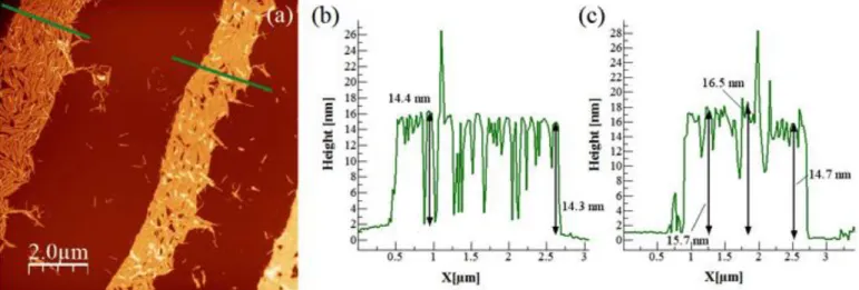
Fig. 2. a) Non-contact AFM of a TMV particle on an oxidized silicon wafer, after contacting
with HMIMI and subsequent rinsing with water. b) Profile marked in (a). The measured height of ~16 nm means that TMV is covered by HMIMI. c) and d) Topography (left) and phase (right) images of TMV patterns. AFM micrographs reveal that the pattern (bright area) on the left is dry, whereas the patterns on the center and on the right are wet.
Further zooming resolved wetting on the nanoscale, confined by virus particles. In the following, we treat the viruses as nearly vertical impenetrable walls. Thus, the spaces between parallel or nearly parallel viruses offer nanoconfinement of the IL, for a certain distance (the virus-virus spacing). We classify the observed wetting structures according to Herminghaus et al. [42], who investigate wetting scenarios of channels experimentally and theoretically, based only on contact angles. Fig. 3 shows a typical F-/pW scenario. That is, a liquid filament (F) with a
negatively curved meniscus (F-) coexists with thin liquid filaments W, which are pinned (p) to
the upper edge of a wall (here a virus). Similar patterns were observed for water/TMV by electron microscopy [35], although at lower resolution. This is indeed expected, based on the similarity of the surface tensions. The F- regime depends on the ratio virus height/virus spacing,
10 arrow) breaks down when the spacing between virions increases and leads to pW filaments (Fig. 3c, blue arrow) which are only attached to one virion. Qualitatively, more confined spaces are filled when more liquid is present, i.e. in areas that are closer to the droplet. We achieved
imaging of nanomenisci with diameter down to 9 nm (Fig. 3). Such extreme curvatures might be interesting candidates to study line tension effects, which - if at all - appear only close to the molecular scale. From Fig. 3 and from similar scans we can also estimate the contact angle of the IL on the substrate, which is here 23° ± 3°. Since tip convolution effects may be at stake in this measurement, this contact angle value must be considered as a minimal value, and can be used for comparisons rather than absolute values. For the wetting dynamics, we refer to the details discussed in the supp. info. We are carrying out similar AFM experiments with water, which requires a humidity chamber. The scenario appears to be very similar, despite the different
surface tension (unpublished data). Although obtained on nanometer scale objects, this result can therefore be explained considering the description of wetting of hydrophilic microstructures, not taking into account nanoscale effects. The latter would be expected for details of the order of only a few molecular diameters, which are not accessible with standard AFM techniques.
Fig. 3. a) Scheme of the wetting of two contiguous TMV particles with HMIMI. b) Phase image.
c) 3D AFM topography of TMV covered by HMIMI. The central part shows a triangular gap between two virus particles, partially filled by the IL, which exhibits a meniscus with a diameter of 9 nm.
We also tested the deposition of larger volumes (of the order of 1 pL) of IL, and the wetting close to the position where the IL was deposited. We found that a slightly less viscous IL is advantageous for such large area studies, and used 1-Butyl 3-Methyl Imidazolium Iodide
11 (BMIMI), which is chemically practically identical to HMIMI. Here we make use of the high viscosity of ILs, as compared to water - any aqueous structure would spread out immediately, and not allow real-time AFM scanning, as described in the following.
As discussed previously, the IL spreads preferentially over the TMV structure (Fig. 4). Large droplets are confined by the microshape of the pattern, showing the expected wettability contrast between the substrate and the TMV-filled patterns. Optical microscopy reveals large IL droplets (several µm in width) and also smaller (micron-sized) droplets, which are just detectable (Fig. 4a). Only AFM images reveal that both types of droplets are connected through TMV-filled patterns (Fig. 4b). AFM also suggests that sub-µm droplets (with diameters of the order of 100 nm) have formed by the transfer of IL over salt impurities or over TMV protein discs, which are both adsorbed on the silicon wafer. In this case the wetting behavior would be explained by an initital D (droplet) regime, according to Herminghaus [42]. The mechanism would be as follows: A large droplet (D) spreads on a TMV-filled pattern since the pattern is hydrophilic, and
surrounded by the slightly hydrophobic substrate (bare wafer)[43]. If some TMV lines stick out of the stripe, a thin liquid filament (type W or F+ [42]) wets the lines. Upon further supply of IL,
the filament elongates. If the TMV lines meet any larger TMV-filled pattern, the filament can again form a droplet D. Note that the contact angle of the large droplets pinned on the TMV pattern, measured on the AFM image, is lower than 𝜃 = 5°. Given the topographical roughness induced by the arrangement of virions, this value can be considered as a maximal value of the contact angle of IL on TMV surface. This value which is difficult to measure by macroscopic methods, therefore confirms the strong hydrophilic nature of the TMV surface.
12
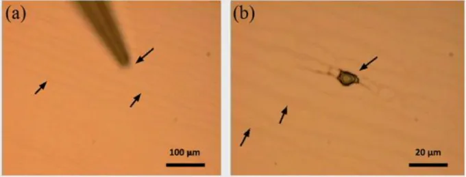
Fig. 4. a) Top left, optical microscope picture of BMIMI on a TMV pattern. b) 3D AFM image of
the region marked with a square in a). The large elongated droplet on the right is connected to smaller droplets (left) by thin wetted lines, made up by wetted TMV.
4.2. Electron microscopy of TMV wetted by ionic liquids
We investigated our TMV/HMIMI samples by electron microscopy (SEM). While this methods gives little information about the height, the lateral dimensions are more reliable, and large areas are more easily scanned than by AFM. Wet regions can be discerned by their low secondary electron yield (dark color), as compared to the highly emissive wafer substrate (bright) (Fig. 5). However, the virions, too, exhibit good (dark) contrast. As previously observed by AFM, IL covers preferentially the TMV arrays and not the Si wafer substrate (Fig. 5). EM analysis permits to detect nanoscale range menisci (Fig. 5b, Fig. 5c), although the resolution is lower than for AFM, and it is impossible to find sub-10 nm menisci. HMIMI microdroplets wet TMV lines in a characteristic way, namely the droplet appears as if covered by spikes.
13
Fig. 5. a) SEM of a HMIMI droplet on TMV patterns. b) SEM micrograph of an array of TMV
particles covered by HMIMI. Arrows: Menisci with radii below 100 nm. c) Details of an HMIMI microdroplet, from which several TMV lines point outwards, given the droplet the appearance of spikes (one spike is marked by an arrow). All scale bars measure 4 µm.
The environmental SEM (ESEM) technique, in conjunction with very good control of a water vapor atmosphere of several hundred Pa, has allowed us to image similar structures of TMV/liquid water [35]. However, the fast spreading dynamics has not allowed recording images analogous to Fig. 5a. Worse, the beam damage in ESEM limits the resolution, such that details as
14 in Fig. 5b and Fig. 5c are not available. Refinement of STEM in water vapor shoul, however, reach that goal.
4.3. Wetting by hydrophobic ionic liquids
The interaction of TMV with hydrophobic liquids is not well known, and one usually expects damage, as found e.g. for toluene [44]. Surprising, this is different for ILs. We tested the hydrophobic IL EMIMFSI (Fig. 6). The virions appear unchanged, except that the topographic height is ~1 nm lower than for hydrophilic IL covered TMV arrays (supp. info Fig. S5), and we recover the height of dry TMVs. The striking difference to the results reported above is that the IL does not cover the TMV pattern completely. Rather, we observed a large phase contrast between the liquid-covered areas and the TMV array (see supp. info Fig. S6). Also, the contrast is the same on the TMV and on the substrate (see Fig. 6, the uncovered area in the top left part of the AFM image marked by an arrow). The wetting behavior could be defined through a F-/cW
regime [42]. That is, filaments with negative pressure (negative ly curved menisci) coexist with thin liquid filaments, where one contact line is located on the side walls. The contact angle of this IL on the substrate is slightly larger than the hydrophilic one (35° instead of 23°). It was not possible to determine it on TMV, but the contact angle is finite and does not vanish, as in the case of hydrophilic IL.
15
Fig. 6. a) Scheme of the wetting of two contiguous TMV particles with hydrophobic EMIMFSI.
b) AFM 3D topography of TMV array covered by the hydrophobic EMIMFSI. c) Top right: AFM phase image.
4.4. Ionic liquids as stains for virions
Negative stains are standards for the imaging of nanoscale biological objects in TEM and STEM at high vacuum. They are usually applied from an aqueous solution that contains a
compound with a heavy element. Upon drying, stains arrange in a halo around nanoscale objects. They should ideally fill all spaces that are occupied by water in typical biological and
biochemical environments. When the object, as in our case TMV, is already dry, the staining solution will cause rehydration. A possible application of ionic liquids is the visualization of biological entities without rehydration, i.e. preserving a dry state. However, for this the ILs should arrange around the usually rather hydrophilic objects. Our results on HMIMI/TMV turned out to be ideal test cases since TMV shows no or very small structural changes upon drying. STEM micrographs display TMV as the familiar rod-like structures for all three protocols (exp. part). For Fig. 7a we had used protocol A. We found here three parallel virions which show the expected width. The narrow space between two virions, which is usually filled by water, is also easily wetted by the IL, which allows to discern every single virion.
Fig. 7b was obtained after preparation with protocol B, described in section 3.2.3 It shows the expected shape of TMV, but also a cloudy irregular coating. A ≈6 nm thick layer covers all of the virus particles, but in some spots it is much thicker. We believe that the
preparation has preserved an early stage of wetting with incomplete removal of surplus IL. This process provides probably the staining mechanism for ILs. For further results on this section see supporting information (Fig. S7, S8, S9).
We have thus proven that the liquid filament structures, which arrange along (and on top of) TMV, act as a local (S)TEM stain, analogous to classical heavy metal stains. This peculiar wetting procedure provides a simple way to improve contrast for the EM observation of elongated nanostructures.
16 a)
b)
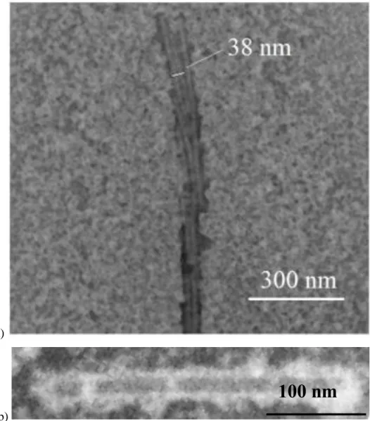
Fig. 7. STEM micrographs of TMV deposited on SiO grid stained with IL HMIMI. a) Parallel TMV lines. The width of each TMV (~19 nm) corresponds to the literature value. b) Single virion surrounded by IL. The contrast is inverted, so the virion corresponds to the grey rectangle, and the white areas are from the IL.
5. Conclusions
We have applied a large variety of preparation methods to obtain nanoscale and microscale ionic liquid (IL) droplets on and at viruses, and observed them by AFM and by electron microscopy (scattering and transmission). The viruses, elongated nanotubes of Tobacco Mosaic Virus (TMV), are present in microscale patterns, which are in turn arranged in a mm scale drying pattern, reminiscent of a coffee stain. Wetting of TMV patterns by hydrophilic IL microdroplets
17 with a volume of the order of 100 fL displays a "F-/pW" scenario, where a liquid filament (F)
with a negatively curved meniscus (F-) coexists with thin liquid filaments W, which are pinned
(p) to the upper edge of the TMV particles. For deposition of larger volumes (of the order of 1 pL), the droplet can spread on the TMV-filled pattern. If some TMV lines stick out of the stripe, a thin liquid filament (type W or F+) wets the lines. Upon further supply of IL, the filament
elongates and can again form a droplet. Wetting of TMV particles with a hydrophobic IL follows a "F-/cW" regime. That is, filaments with negative pressure coexist with thin liquid filaments,
where one contact line is located on the TMV particles. Since these results can be interpreted considering only macroscopic descriptions based on surface tension and contact angles, they are expected also for water. In particular, both types of liquids share moderate to high surface tensions which leads to similar wetting behaviours. On the other hand, nanoscale effects that go beyond macroscopic concepts such as surface tension or viscosity, operate very close to the scale of a single molecule. Hence , as the available techniques do not (yet) allow for the required high-resolution imaging for water nanostructures we believe that nanoscale wetting patterns, such as the filaments made of hydrophilic ILs, are a good first approach to wetting patterns of water. Experiments with water are underway to assess if the peculiar chemical nature of ILs and water affects their wetting behavior at nanoscale. In a further analogy, the filaments act as a local stain for the TMV particles, which affords a simple method to improve contrast for electron microscopic observation of dry biological entities. Our strategy avoids the rehydration by standard aqueous stains.
Acknowledgements
We acknowledge funding from Red Temática de Excelencia en Física Virológica (Retos,
Spanish Ministry of Economy, Industry and Competitiveness, MINECO), from FEI (Eindhoven, NL), from Elkartek 2015 and 2017 (Basque Government), MAT2013-46006-R (MINECO), from the Basque Government Grant Proyecto de Investigación PI2013-57, and from the Maria de Maeztu "Units of Excellence" Programme MDM-2016-0618 (MINECO). We thank Andrey Chuvilin (nanogune), Christina Wege (Uni Stuttgart), and Christopher Tollan for their help and discussions.
18 [1] T. Young, An essay on the cohesion of fluids, Philos. Trans. R. Soc. London 95 (1805) 65– 87.
[2] J. F. Joanny, P. G. De Gennes, A model for contact angle hysteresis. J. Chem. Phys. 81 (1984) 552–562.
[3] P. G. de Gennes, Deposition of langmuir-blodgett layers. Colloid Polym. Sci. 264 (1986), 463–465.
[4] D. Bonn, J. Eggers, J. Indekeu, J. Meunier, E. Rolley, Wetting and spreading. Rev. Mod. Phys. 81 (2009), 739–805.
[5] M. Rauscher, S. Dietrich, Wetting phenomena in nanofluidics, Annu. Rev. Mater. Res. 38 (2008) 143–172.
[6] Y. Yuan, T. R. Lee, Contact angle and wetting properties, in: G. Bracco, B. Holst (Eds.), Surface Science Techniques, Springer, Berlin Heidelberg, 2013, pp. 3–34.
[7] H. J. Butt, D. S. Golovko, E. Bonaccurso, On the derivation of Young's equation for sessile drops: nonequilibrium effects due to evaporation. J. Phys. Chem. B, 111 (2007), 5277–5283. [8] S. Dietrich, M. Rauscher, M. Napiórkowskic, Wetting phenomena on the nanometer scale, in: Thierry Ondarçuhu and Jean-Pierre Aimé (Eds.), Nanoscale Liquid Interfaces: Wetting,
Patterning, and Force Microscopy at the Molecular Scale, Pan Stanford Publishing Pte. Ltd., Singapore, 2013, pp 83–153.
[9] A. Checco, Liquid spreading under nanoscale confinement. Phys. Rev. Lett. 102 (2009) 106103.
[10] D. Mattia, V. Starov, S. Semenov, Thickness, stability and contact angle of liquid films on and inside nanofibres, nanotubes and nanochannels, J. Colloid Interface Sci. 384 (2012), 149– 156.
[11] E. Lauga, M. P. Brenner, H. A. Stone, The no-slip boundary condition: a review in: C. Tropea, A. L. Yarin, and J. F. Foss (Eds.), Springer Handbook of Experimental Fluid Mechanics, Part C, Springer, Berlin, 2007, pp 1219–1240.
[12]M.Whitby, L. Cagnon, M. Thanou, N. Quirke, Enhanced fluid flow through nanoscale carbon pipes. Nano letters, 8 (2008), 2632–2637.
[13] E. Secchi, S. Marbach, A. Niguès, D. Stein, A. Siria, L. Bocquet, Massive radius-dependent flow slippage in carbon nanotubes, Nature 537 (2016) 210–213. [14] Z. Lei, B. Chen, Y.-M. Koo, D. R. MacFarlane, Introduction: ionic liquids, Chem. Rev. 117 (2017) 6633–6635.
19 [15] Z. Zhang, J. Song, B. Han, Catalytic transformation of lignocellulose into chemicals and fuel products in ionic liquids, Chem. Rev. 117 (2017) 6834–6880.
[16] K. S. Egorova, E. G. Gordeev, V. P. Ananikov, Biological activity of ionic liquids and their application in pharmaceutics and medicine, Chem. Rev. 117 (2017) 7132–7189.
[17] M. Watanabe, M. L. Thomas, S. Zhang, K. Ueno, T. Yasuda, K. Dokko, Application of ionic liquids to energy storage and conversion materials and devices. Chem. Rev. 117 (2017) 7190–7239.
[18] L-M. Joubert, K. McDonald, SEM visualization of biological samples using Hitachi ionic liquid HILEM® IL 1000: a comparative study, Microscop. Microanal. 22 (2016) 1170–1171. [19] L.-O. Heim, E. Bonaccurso, Measurement of line tension on droplets in the submicrometer range, Langmuir, 29 (2013) 14147–14153.
[20] J. Dupré de Baubigny, M. Benzaquen, Laure Fabié, M. Delmas, J.-P. Aimé, M. Legros, T. Ondarçuhu, Shape and effective spring constant of liquid interfaces probed at the nanometer scale: finite size effects, Langmuir 31 (2015) 9790−9798
[21] J. Dupré de Baubigny, M. Benzaquen, C. Mortagne, C. Devailly, S. K. Acharige, J. Laurent, A. Steinberger, J.-P. Salvetat, J.-P. Aimé, Thierry Ondarçuhu. AFM study of hydrodynamics in boundary layers around micro- and nanofibers, Phys. Rev. Fluids 1 (2016) 044104.
[22] C. Herrera, G. García, M. Atilhan, S. Aparicio, Nanowetting of graphene by ionic liquid droplets, J. Phys. Chem. C 119 (2015) 24529–24537.
[23] R. Burt, G. Birkett, M. Salanne, X. S. Zhao, Molecular dynamics simulations of the
influence of drop size and surface potential on the contact angle of ionic-liquid droplets. J. Phys. Chem. C 120 (2016) 15244–15250.
[24] H. J. Castejon, T. J. Wynn, Z. M. Marcin, Wetting and tribological properties of ionic liquids, J. Phys. Chem. B 118 (2014) 3661−3668.
[25] Y. Guan, Q. Shao, W. Chen, S. Liu, X. Zhang, Y. Deng, Dynamic three-dimensional nanowetting behavior of imidazolium-based ionic liquids probed by molecular dynamics simulation, J. Phys. Chem. C 121 (2017) 23716–23726.
[26] K. Kawai, K. Kaneko, H. Kawakami, T. Yonezawa, Bioinspired choline- like ionic liquids: their penetration ability through cell membranes and application to SEM visualization of hydrous samples, Langmuir 27 (2011) 9671–9675.
20 [27] Y. Ishigaki, Y. Nakamura, T. Takehara, N. Nemoto, T. Kurihara, H. Koga, H. Nakagawa, T. Takegami, N. Tomosugi, S. Miyazawa, S. Kuwabata, Ionic liquid enables simple and rapid sample preparation of human culturing cells for scanning electron microscope analysis. Microsc. Res. Tech. 74 (2011), 415–420.
[28] T. Hamano, A. Dwiranti, K. Kaneyoshi, S. Fukuda, R. Kometani, M. Nakao, H. Takata, S. Uchiyama, N. Ohmido, K. Fukui, Chromosome interior Observation by Focused Ion
Beam/Scanning Electron Microscopy (FIB/SEM) Using Ionic Liquid Technique, Microsc. Microanal. 20 (2014) 1340–1347.
[29] J.M. Alonso, M.Ł. Gٖ órzny, A.M. Bittner, The physics of tobacco mosaic virus and virus-based devices in biotechnology, Trends Biotech. 31 (2013) 530–538.
[30] N. Byrne, B. Rodoni, F. Constable, S. Varghese, J. H. Davis, Enhanced stabilization of the tobacco mosaic virus using protic ionic liquids. Phys. Chem. Chem. Phys. 14 (2012), 10119– 10121.
[31] M. Knez, M. P. Sumser, A. M. Bittner, C. Wege, H. Jeske, D. M. P. Hoffmann, K. Kuhnke, K. Kern, Binding the Tobacco mosaic virus to inorganic surfaces, Langmuir 20 (2004) 441–447. [32] A. R. Voet, J. R. Tame, Protein-templated synthesis of metal-based nanomaterials, Curr. Opin. Biotechnol. 46, (2017) 14–19.
[33]A. P. Fang, E. Dujardin, T. Ondarçuhu, Control of droplet size in liquid nanodispensing, Nano Lett. 6 (2006) 2368−2374.
[34] L. Fabie, T. Ondarcuhu, Writing with liquid using a nanodispenser: spreading dynamics at the sub-micron scale, Soft Matter 8 (2012) 4995−5001.
[35] J. M. Alonso, F. Tatti, A. Chuvilin, K. Mam, T. Ondarçuhu, A. M Bittner, The condensation of water on adsorbed viruses, Langmuir 29 (2013) 14580−14587.
[36] Y. Lin, Z. Su, G. Xiao, E. Balizan, G. Kaur, Z. Niu, Q. Wang, Self-assembly of Virus Particles on Flat Surfaces via Controlled Evaporation. Langmuir 27 (2011) 1398−1402. [37] M. Ben Ali, T. Ondarçuhu, C. Joachim, Atomic force microscope tip nanoprinting of gold nanoclusters, Langmuir 18 (2002) 872−876. [38] J. Rong, Z. Niu, L. A. Lee, Q. Wang, Self-assembly of viral particles, Curr. Opin. Colloid Interface Sci. 16 (2011) 441–50.
[39] A. Calò, A. Eleta-Lopez, P. Stoliar, D. De Sancho, S. Santos, A. Verdaguer, Alexander M. Bittner, Multifrequency Force Microscopy of Helical Protein Assembly on a Virus, Sci. Rep 6 (2016) srep21899.
21 [40] W. C. Shu-wen, M. Odorico, M. Meillan, L. Vellutini, J. M. Teulon, P. Parot,B. Bennetau, J. L. Pellequer, Nanoscale structural features determined by AFM for single virus particles, Nanoscale, 5 (2013) 10877−10886.
[41] M. Knez, A. M. Bittner, F. Boes, C. Wege, H. Jeske, E. Maiβ, K. Kern, Biotemplate synthesis of 3-nm nickel and cobalt nanowires, Nano Lett. 3 (2003) 1079−1082.
[42] S. Herminghaus, M. Brinkmann, R. Seemann, Wetting and Dewetting of Complex Surface Geometries. Annu. Rev. Mater. Res. 38 (2008), 101−121.
[43] T. Ondarçuhu, Total or partial pinning of a droplet on a surface with a chemical discontinuity, J. Phys. II, 5 (1995) 227−241.
22
Supplementary material
Nanoscale Wetting of Viruses by Ionic Liquids
José María Alonso,a Thierry Ondarçuhu,b,c* Coralie Parrens,b Marcin Gorzny,a
Alexander M. Bittnera,d,*
a CIC nanoGUNE, Tolosa Hiribidea 76, E-20018 Donostia-San Sebastián, Spain b CEMES-CNRS, 29 rue Jeanne Marvig, 31055 Toulouse cedex 4, France c IMFT, 2 allée du professeur Camille Soula, 31400 Toulouse, France
d IKERBASQUE, Basque Foundation for Science, María Díaz de Haro 3, 48013 Bilbao, Spain
Spreading of the hydrophilic IL HMIMI on TMV patterns
Optical microscopy (Fig. S1) visualizes the deposition of a droplet of a hydrophilic ionic liquid. The band-like lines are TMV patterns - the very high local density of virions provides a faint contrast.
Fig. S1. HMIMI ionic liquid is deposited with a microinjector on TMV band-shaped patterns
(three of the bands are pointed out by arrows). HMIMI spreads preferentially on the TMV patterns and not on the substrate. A video regarding this process is available.
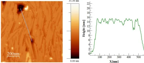
23 Spreading of the hydrophilic HMIMI on the TMV patterns can also be achieved by deposition from a modified hollow AFM tip (NADIS). In this case, the deposited droplet has a diameter of about 1 µm which corresponds to a volume of the order of 40 aL. In Fig. S2, the droplet is clearly visible on the topographic image and the area around the droplet appears smoother than on the left stripe which is not contact with liquid. Wetting behavior follows the F-/pW regime discussed above. The AFM phase micrograph shows a darker contrast in the areas surrounding the IL droplet which confirms the presence of IL spreading over the TMV pattern.
Fig. S2. (a) AFM topography image of TMV patterns dry (left) and wet with HMIMI. (b) Profile
of the dry TMV pattern. (c) AFM profile of wet TMV pattern.
This procedure allows to locate approximately the liquid front, as sketched in Fig. S3 (right). Note that the front is asymmetric due to the time required (about 16 min) to scan the whole image (from top to bottom). A rough estimate leads to a front velocity of the order of a few nm/s. As shown in Fig. S3 left the liquid droplet has completely disappeared in the second scan.
24
Fig. S3 Left, topography micrograph of hydrophilic IL HMIMI droplet deposited on a TMV
pattern. Right, phase AFM image. The areas surrounding the droplet display a higher contrast comparing to the Si wafer substrate. It indicates that HMIMI IL spreads rapidly over the TNV pattern.
The dynamics was also assessed by following the spreading of microdroplets in real time. A 10 µm droplet was deposited on a TMV stripe pattern, which was imaged continuously about 20 µm from the reservoir droplet. In Fig. S4, the stripe pattern was more concentrated and composed of 2 layers of TMV. As shown by the dark contrast in the phase image the bottom layer on the substrate was already filled when imaging started. At some point, a liquid front also invaded the top layer as evidenced either on topo and phase image. The liquid front is not
straight but the liquid ends up filling most of the top layer. An estimate of the velocity is again in the nm/s range.
25
Fig. S4. Top: topographic image of HMIMI spreading on a dense TMV layer; Bottom: phase
26
Spreading of the hydrophobic IL EMIMFSI on TMV
We here present additional AFM images (Fig. S5, Fig. S6), obtained after application of EMIMFSI, as described in the main text.
Fig. S5. Left. Topography picture of TMV pattern covered with hydrophobic EMIMFSI. Left
profile define on the left. The height (~15 nm) is slightly lower than that found for TMV structures covered with HMIMI (~16 nm).
27
Fig. S6. Left, topography micrograph of TMV arrays covered by hydrophobic EMIMFSI. Right,
phase image. Below, 3D reconstruction.
STEM imaging of TMV particles covered by HMIMI
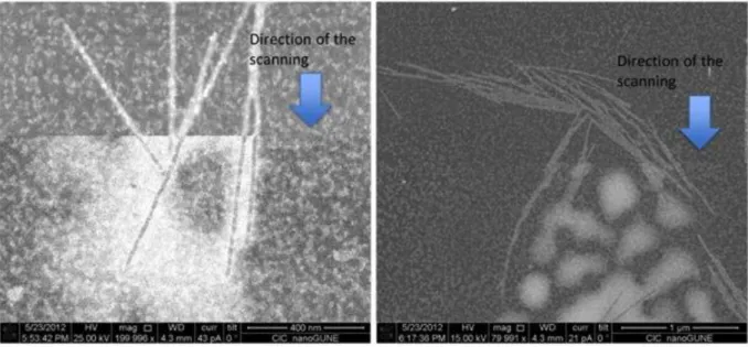
We first focus on the potentially problematic beam damage in SEM and STEM. When STEM-scanning a frame (micrograph) for a second time (Fig. S7), with longer frame time (107 s instead of 54 s), the beam of the electron microscope source interacts with residual IL. As a consequence the spots that correspond to HMIMI disappear. Literature describes the
decomposition of lead and cadmium iodide by electron irradiation [1,2], therefore we believe that iodide atoms I- oxidize to iodine I
2 and subsequently evaporates. Several reactions of iodine
with TMV are documented in aqueous phase [3−5]; iodine is supposed to bind to the (few) tyrosine residues, and structural damage is not expected. We always carefully monitored the damage, which can be reduced by choosing low beam currents.
Fig. S7. STEM micrograph (contrast inverted) of TMV arrays covered with HMIMI and scanned
for a second time. Arrows pointed to the front/line of scanning. The frame area above the line has been scanned twice while the area below the front has been scanned only once.
The identity of iodide-containing ILs (HMIMI) can be tested by energy dispersive X-ray (EDX) analysis of the larger (micro)droplets. The substrate contributes large Si signals, the C signal stems from virions (if present) and from contamination, but the I lines can only be from HMIMI.
28
Fig. S8. EDX analysis of an HMIMI microdroplet on a Si wafer, carried out in an SEM. Typical
elemental lines are marked.
The mentioned micro- and nanodroplets of the IL coexist with stained virions, as shown in Fig. S9.
Fig. S9. STEM micrograph of TMV lines covered with HMIMI, and of HMIMI nanodroplets.
29
AFM height measurements on virions
We collected the following statistics:
Bare TMV (blue bars in Fig. S10): 4 different samples, 10 different AFM images, 40 measurements, height = 14.09 -/+ 0.2 nm
TMV in contact with hydrophilic HMIMI (orange bars): 4 different samples, 18 different AFM images, 60 measurements, height = 16.17 -/+ 0.18 nm
TMV in contact with hydrophobic EMIMFSI (grey bars): 3 different samples, 8 different AFM images, 30 measurements, height = 14.22 -/+ 0.23 nm
Fig. S10. Histogram of AFM height data for bare TMV (blue), and TMV covered by EMIMFSI
(grey) and HMIMI (orange)
We believe that the rather low scatter of the data (over different samples, with different tips, and experimentalists) shows that the imaging conditions do not play a significant role. We can be very confident in the heights we measure.
30
Comparison of ionic liquids with water
The interaction of the ILs with TMV is governed by the hydrophilicity / hydrophobicity of the ILs, as it would happen for common polar and apolar solvents. For the ILs of this work the hydrophilicity/hydrophobicity is mostly determined by the anion as reported in the literature [6]. In that regard, our research has been performed with N,N’-dialkylimidazolium salts, specifically: 1-butyl-3-methylimidazolium iodide (BMIMI), 1-ethyl-3-methylimidazolium trifluoromethanesulfonate (EMIMTFO), hexyl-3-methyl imidazolium iodide (HMIMI) and 1-ethyl-3-methylimidazolium bis(fluorosulfonyl)imide (EMIMFSI). For these molecules the amphiphilicity is located in the cation because the imidazolium ion (the polar region of the cation) is substituted by alkyl residues (the apolar region of the cation). EMIMTFO and EMIMFSI both possess the same amphiphilic cation (1-ethyl-3-methylimidazolium), but EMIMTFO is hydrophilic, i.e. miscible with water due to the trifluoromethanesulfonate anion, while EMIMFSI is hydrophobic, i.e. not miscible with water, due to the bis(fluorosulfonyl)imide anion. On the contrary, BMIMI and HMIMI possess different amphiphilic cations (1-butyl-3-methylimidazolium and 1-hexyl-3-methyl imidazolium, respectively) but display the same anion (iodide). Both ILs are hydrophilic. Therefore the IL-virus interaction is governed by the hydrophilicity/hydrophobicity of the ILs but not by the amphipathy of the cationic and/or anionic components of the IL.
Regarding the similarities and differences between the wetting of IL and water molecules on viruses, it is important that the nanoscale wetting by hydrophilic ILs, confined by virus particles, shows a typical F-/pW scenario, as we reported for the wetting of TMV particles on oxidized
silicon [7]. On the contrary, the wetting of TMV particles with hydrophobic IL follows a F-/cW
regime. This scenario does not occur with the wetting of TMV particles with water, no matter if the TMV particles were deposited on a hydrophilic surface (oxidized silicon) or on a hydrophobic surface (gold CA 70°, HMDS modified silicon CA 70°, or carbon foil CA 100°) [7].
31
REFERENCES
[1] A. J. Forty, The precipitation of lead during decomposition of lead iodide by electron irradiation, Philos. Mag. 67 (1961), 895−905.
[2] S. D. Sharma, K. Mehrotra, V. K. Agrawal, Electron microscopic study of decomposition in vapour grown cadmium halide crystals, J. Crystal Growth 44 (1978) 44, 325−328.
[3] H. Fraenkel-Conrat, The reaction of tobacco mosaic virus with iodine, J. Biol. Chem. 217 (1955) 373−382
[4] J. Graham, P. J. G. Butler, Location of tyrosine residues in the disk of tobacco‐ mosaic‐ virus protein and comparison of the subunit packing with that of the virus, FEBS J. 83 (1978) 523−528.
[5] M. A. Mayo, E. C. Cocking, Labelling of tobacco mosaic virus with 125I, J. Gen. Virol. 2
(1968), 89−97.
[6] J. G. Huddleston, A. E. Visser, W. M. Reichert, H. D. Willauer, G. A. Broker, R. D. Rogers, Green Chemistry 3 (2001) 156
[7] J. M. Alonso, F. Tatti, A. Chuvilin, K. Mam, T. Ondarçuhu, A. M Bittner, Langmuir 29 (2013) 14580