Publisher’s version / Version de l'éditeur:
Vous avez des questions? Nous pouvons vous aider. Pour communiquer directement avec un auteur, consultez la
première page de la revue dans laquelle son article a été publié afin de trouver ses coordonnées. Si vous n’arrivez pas à les repérer, communiquez avec nous à PublicationsArchive-ArchivesPublications@nrc-cnrc.gc.ca.
Questions? Contact the NRC Publications Archive team at
PublicationsArchive-ArchivesPublications@nrc-cnrc.gc.ca. If you wish to email the authors directly, please see the first page of the publication for their contact information.
https://publications-cnrc.canada.ca/fra/droits
L’accès à ce site Web et l’utilisation de son contenu sont assujettis aux conditions présentées dans le site LISEZ CES CONDITIONS ATTENTIVEMENT AVANT D’UTILISER CE SITE WEB.
Technical Translation (Canada Institute for Scientific and Technical Information); no. NRC-TT-2066, 1983
READ THESE TERMS AND CONDITIONS CAREFULLY BEFORE USING THIS WEBSITE.
https://nrc-publications.canada.ca/eng/copyright
NRC Publications Archive Record / Notice des Archives des publications du CNRC :
https://nrc-publications.canada.ca/eng/view/object/?id=473b235e-3622-4cd3-8ae6-fd2847ac035c https://publications-cnrc.canada.ca/fra/voir/objet/?id=473b235e-3622-4cd3-8ae6-fd2847ac035c
NRC Publications Archive
Archives des publications du CNRC
For the publisher’s version, please access the DOI link below./ Pour consulter la version de l’éditeur, utilisez le lien DOI ci-dessous.
https://doi.org/10.4224/20386586
Access and use of this website and the material on it are subject to the Terms and Conditions set forth at
Construction of an Ice Model Basin at the Ship Research Institute of
the Ministry of Transportation
TECHNICAL TRANSLATION TRADUCTION TECHNIQUE 2066 Author/Auteur: Title/Titre: Reference/Reference: Translator/Traducteur:
Mitsui Shipbuilding Co., Ltd.
Construction of an ice model basin at the ship
research institute of the Ministry of Transportation. Technical Reports of Mitsui Shipbuilding Co., Ltd. No. 114.
R. Robb ,
Canada Institute for Scientific and Technical Information
Institut canadien de l'information scientifique et technique
Ottawa, Canada KIA OS2
---
-Technical Reports of Mitsui Shipbuilding Co., Ltd., No. 114 (Reprint),
!W.
91-102CONSTRUCTION OF AN ICE MODEL BASIN AT THE SHIP RESEARCH INSTITUTE OF THE MINISTRY OF TRANSPORTATION
Systems Engineering Division
A water tank designed to artificially reproduce icy sea
conditions was built for the first time in Japan at the Ship Research Institute of the Ministry of Transportation in 1981. This test
basin, which may also be referred to as an "ice model basin", makes it possible to conduct experiments that are intended to solve the technical problems faced by ships sailing through icy seas.
The ice model basin was constructed in an insulated building and a cooling system was installed to make the water in the tank freeze at its surface. Since salt water is used and the room temperature is kept at _200
C, this cooling system is able to produce a sheet of ice approximately 40 rom thick in 15 hours. That is to say, the test basin is able to reproduce icy seas overnight and thus makes it possible to perform these experiments daily.
Special consideration was given to the basic design and
insulation of the building and the basin so as to ensure that they could withstand rapid and repeated temperature changes. The
machinery that was installed included not only the aforementioned cooling system, which had a total refrigerating capacity of 229,180 kcal/hr, but also a heating system, equipment for producing salt water, a system for crushing ice and discharging it, a towing carriage, various accessories, etc.
The Mitsui Shipbuilding Co., Ltd., had the good fortune to receive the opportunity to participate in the construction of all of these facilities except for one part of the test basin.
This paper provides an introductory look at these facilities, outlining their features and the experimental data that have been obtained using them. The discussion focuses principally on the unique characteristics of the facilities.
1. Introduction
Abundant resources lie untapped within the Arctic Circle, both on land and under the sea. These include not only oil and natural gas, but also iron ore, coal, nickel and many other resources. The reserves of oil and natural gas, however, are especially large, so immense, in fact, that they reputedly are second only to those found in the Middle East.
In
1968 petroleum was discovered in the North Slope region of Alaska, and ever since that time North American and various European countries have earnestly been conducting research and development projects aimed at devising a transportation system for this oil. Furthermore, spurred by the trial sailing of the Arctic Ocean undertaken in 1969 by the lice-breaker] the Manhattan, expectations arose that there would be an early clarification of the technical problems faced by ships and maritime structures operating in icy seas. Studies based on model experiments provide an effective means of systematically and efficiently gaining a good understanding of theseproblems. As a result, experimental facilities containing specially designed water tanks have been constructed in an attempt to simulate the various
features of icy seas. Such tanks which reproduce the conditions encountered in icy seas have already been built in the United States, Canada, West
Germany and the U.S.S.R., among other countries, and a number of different types of model experiments have been performed. However, the older types of ice-water tanks that were constructed in the early stages of this research were found to have various problems connected with the structure of the tanks themselves, their cooling systems and the systems used to gather the required data. Thus in the last few years the countries involved in these studies have all been redesigning their test facilities or devising new ones in a feverish attempt to amass the technology that is needed for operations in icy seas.
4
-Here in Japan, too, the Ship Research Institute of the Ministry of Transportation has carried out a series of studies aimed at developing a system for transporting northern resources, and facilities for promoting this イ・ウ・。セ」ィ and development effort have been established by the institute. The first step in this direction was to plan the construction of a test basin that could make it possible to conduct experiments on the ability of ships, etc., to operate in icy seas. As a result of surveys and other
investigations carried out from 1975 on, the Ship Research Institute had outdoor transformer equipment installed on its grounds (located in the city of Mitaka) in March, 1979, and by March of the following year the institute had completed the construction of a building, which contained a test basin, both a main section and an upper part, and another elevated area that was to be used when preparing for the experiments, etc.; and had also set in place much of the equipment that would be required, including a tank for holding
concentrated salt water, refrigerating equipment, and other machinery.
B.Y
March of 1981 the various types of apparatuses that would be employed in gathering data during the model ship experiments had been prepared and installed. Included among these were devices such as a towing carriage, rails, and a trolley, as well as equipment for regulating ice compression and for purifying the water in the basin, and also various testing instruments such as a resistance dynamometer designed for use in ice, a bending tester for [measuring} ice compression, and so on. At this point the construction of Japan's first model basin for testing the naVigation of ships in icy waters had been completed.
The Mitsui Shipbuilding Co., Ltd., received the contract from by the Kanto Regional Construction Bureau of the Ministry of Construction and the
S4ipbuilding Research Institute of the Ministry of Transportation to design and construct nearly all the facilities required for this ice model basin. This work included the design and construction of the basic water tank that served as the test basin and the building that housed it, and also
involved designing, manufacturing and installing the towing carriage and various types of machinery arid accessory equipment that was required. No problems were encountered in completing this construction project. It can be
said that the finished facility is essentially an ultra-large refrigerator that incorporates a water tank. Since the performance of the cooling system is directly influenced by the insulation properties of the building and the test basin itself, Mitsui Shipbuilding Co., Ltd., was given the
responsibility of constructing the entire facility - i.e., not only the test basin itself but the building, too - so as to ensure that the model basin would be able to satisfactorily reproduce icy sea conditions.
The following sections will give an overview of the technology employed in constructing the facility, with special attention being paid to the
machinery that had been installed, and data on the facility's operations will also be provided.
2. Purpose of the Facility
!n this facility a water tank that has been installed inside a room is utilized to artificially reproduce icy sea conditions (that is, conditions such that the entire surface of the water is frozen [in some areas while] chunks of ice float at the surface [in other areas]; hereafter this tank will be referred to as an "ice model basin" or "test basin") so that studies can be performed using model ships to investigate the various types of pressures connected with the ice and the hydrodynamic forces that act on ships when
6
-they navigate in icy seas and on other structures that may be emplaced in such waters. That is to say,
(I) The room is cooled down to a minimum temperature of
-35
0C by coils installed on the ceiling [above] the test basin. As a result, a sheet
of ice that extends over the entire surface of the water and has a uniform thickness of approximately 40 mm can usually be produced overnight.
(2) Various measurements are made of the ability of a model ship or other structure to operate under the "icy sea" conditions created as
described above. Data are collected on the resistance that the model ship, etc., encounters as it breaks through the sheet of ice that covers the entire water surface, with measurements being made of the pressure exerted by the ice, the impact load, the ship's speed, acceleration, thrust, torque, propeller speed, hull motion, and so on. In these experiments the model
ship, etc., is either towed by the towing carriage along steel rails installed at the upper edges of the test basin, or moves on its ovm power with the assistance of a guide device on the towing carriage.
(3) While the above data are being gathered, observations and additional measurements are made to determine the mechanism by which the ice sheet is broken and how the resulting chunks of ice behave as the model ship passes through the sea. This information is collected through observation windows installed at the bottom and at the sides of the test basin.
(4) These experiments are repeated using different types of model ships, different navigation conditions, and ice sheets of different strengths.
(5) In addition, various types of model experiments are conducted to duplicate some other conditions that actual ships are likely to encounter
when navigating through real icy seas. These include model experiments using seas that essentially consist of floating chunks of ice, experiments on
extricating model ships that have become locked up in an ice sheet, etc.
3.
Basic PlanAs yet the new field of cryoengineering has no established methodology, and even the basins used to reproduce icy sea conditions have different characteristics in different countries, varying with respect to structural form, their cooling systems, methods of operation, etc. The facility discussed in this paper was designed and constructed in accordance with a number of basic conditions stipulated by the Kanto Regional Construction Bureau of the Ministry of Construction. These guidelines, which were
formulated on the basis of such considerations as the anticipated direction of future research in this field and on Japan's environmental conditions, were as follows.
3.1 Basic Dimensions
Interior dimensions of the finished test basin: length
35
m, breadth 6 m, depth 2.1 m.Standard depth of the water in the test basin: 1.8 m.
Interior dimensions of the finished trim tank: length 8 m, breadth 1.6 m, depth 1.2 m.
Standard depth of the water in the trim tank: 0.9 m,
Interior dimensions of the preparation room for the experiments: 12 m x 16 m.
Available vertical space within the basement: 1.8 m.
Size of areas available for observations within the test basin: 0.9 m x 0.9 m (bottom of basin); 0.9 m x 0.7 m (side of basin).
8
-Maximum height of building: no more than 10 m above ground level. *
3.2
Basic Capabilities Required (1) Roan Housing the Test BasinRoom temperature
Temperatures ordinarily used
Error for temperature setting
_20° C (while water frozen) 0° C (during experimentsl
Variation of temperature within the room (statistical dispersion)
TIO C
Freezing speed 40 rnm/15 hr at a room
temperature of _20° C and a salinity level of
3070Q'
(2) Trim Tank Room and the Basement
Room temperature variable from 0-10° C
Variation of temperature within the room (statistical dispersion)
(3) Cooling of the Water Supplied to the Model Ice Basin (Including Water Poured into the Basin)
Well water [originally] at a temperature of 16° C is supplied to the basin at 5° C and at a rate of 7.8 cu mjhr.
3.3
Design Conditions (1) Cooling MethodMOdel ship experiments conducted in a uniform sheet of ice bear a
similarity to the resistance- and self-propulsion tests that are carried out in calm water in the water tanks ordinarily employed for ship experiments. Since model experiments of this type prOVide a principal means of
understanding a ship's performance in icy seas, it is very important to *Translator's note: Inference; the text literally says "within 10 m from GL".
ensure that the ice sheets used in these tests are highly uniform as far as their thickness is concerned. To this end a natural-convection type of cooling method was adopted, utilizing coils installed on the ceiling above the test basin in a uniform pattern 、セウゥァョ・、 to cover the entire surface [of the baainl ,
(2) Insulation Design
(a) The test basin was constructed with an empty space at its bottom so as to exclude unwanted effects caused by variations in the ground temperature. The basin was also built so that it could be entirely enclosed within an
insulated building.
(b) The [facilityl was designed to ensure that the temperature distri-bution within the roams would remain uniform and not be disrupted by the
intrusion of heat from outside.
(c) The insulation materials that were selected for the facility were ones that have low thermal conductivity, particularly in the low-temperature region, and little capacity for absorbing water or vapor. Another prime consideration was that their insulating ability should not deteriorate with time.
(d) Thorough attention was paid to the possibility that moisture might condense on the exterior [of the test basin] as a result of the repetition of the cooling cycle over a lengthy period of time, and, when necessary,
appropriate measures were taken to damp proof the facility and prevent the formation of dew, and to ensure adequate ventilation and drainage.
(3) Test Schedule
Experiments were conducted in the facility according to the following schedule of operations, with one cycle being completed every six weeks. As a
- - -- - - -MMMZN⦅セ
10
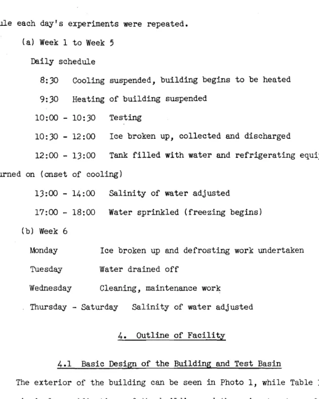
-rule each day's experiments were repeated. (a) Week 1 to Week 5
Daily schedule
8:30 Cooling suspended, building begins to be heated 9:30 Heating of building suspended
10:00 - 10:30 Testing
10:30 - 12:00 Ice broken up, collected and discharged
12:00 - 13:00 Tank filled with water and refrigerating equipment turned on (onset of cooling)
13:00 - 14:00 Salinity of water adjusted
17:00 - 18:00 Water sprinkled (freezing begins) (b) Week 6
Monday Ice broken up and defrosting work undertaken Tuesday Water drained off
Wednesday Cleaning, maintenance work
Thursday - Saturday Salinity of water adjusted 4. Outline of Facility
4.1 Basic Design of the Building and Test Basin
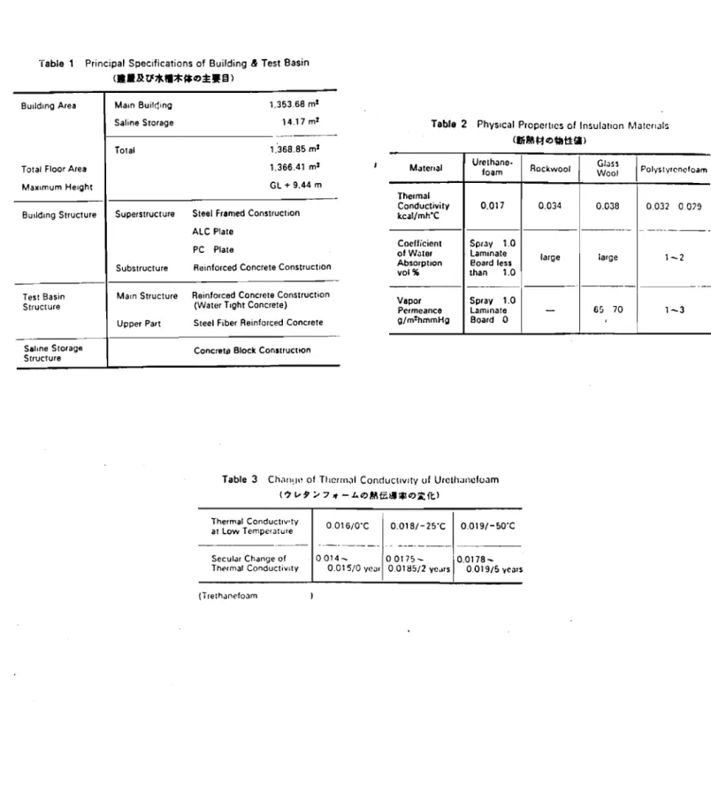
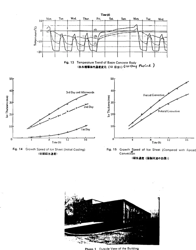
The exterior of the building can be seen in Photo 1, while Table 1 lists the principal specifications of the building and the main structure of the test basin.
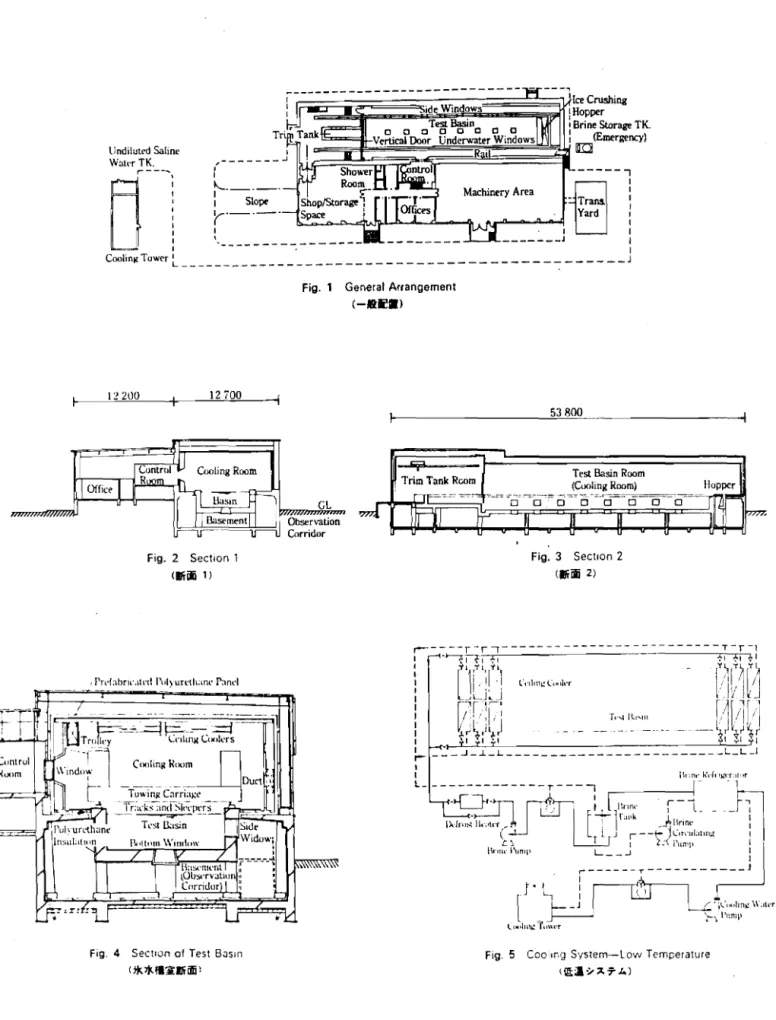
4.1.1 General Arrangement
Figure 1 shows the general layout of the building. The building containing the test basin is a steel-framed reinforced concrete structure
35.8
m long, 12.7 m wide and8.3
m high that consists of a trim tank room, a test basin room, and an ice-crushing hopper room. Parallel to this is amore elevated structUre 53.8 m long, 12.2 m wide and 5.15 m high that is used for preparing the experiments; included within this area are a preparation room for the experiments, a control room, a control panel room, a machinery room, study roams, etc. Moreover, there is also some outdoor equipment, including a tank holding concentrated salt water, a cooling tower,
transformer equipment and a tank where brine can be recovered and stored in case of emergency. Thermal isolation of the test basin room from the trim tank room was accomplished by using a pair of motor-operated insulating doors situated within the water and above the water, with the result that the
surface of the water in the trim tank room will not freeze even when the temperature in the test basin room falls to -350
C. When the insulating door above the water is raised, the test basin room and trim tank room
merge together, making it possible to operate the towing carriage that is normally housed in the trim tank room. Towing experiments can be conducted with the model ships by further lowering the insulating door that is situated within the water. The ice-crushing hopper room is joined together with the test basin room, and the opening at the upper part of the hopper is thermally isolated by means of an insulating door from the ice-crushing equipment and discharging pipe at the bottom [of the hopperl. Double heat-insulating doors are installed between the trim tank room and the test-preparation room; this serves not only to prevent the incursion of warm air and the consequent loss of cold air, but it also provides a space that makes it possible for the experimenter to regulate the temperature. The floor of the control room was designed to be higher than the floor of the test-preparation area, and care was taken to install observation windows that would make it possible to monitor what was happening inside the test basin. The machinery room was given an independent foundation to ensure that vibrations from the machines
12
-would not be transmitted to the test basin. Moreover, the salt repository and the cooling tower part of the refrigerating machine were placed a slight distance away from the building, and, as a countermeasure against noise, the two were joined together and enclosed within a block. The tank holding concentrated salt water was placed underground directly below the salt repository.
4.1.2 Test Basin. Etc.
Figures 2 and 3 show cross sections of the building. Since the test basin room was repeatedly cooled and heated, each day going from _20· C to O· C and back again to _20· C, it was essential that the main structure of the basin itself be strong enough to withstand the temperature
fluctuations. It was especially important to ensure that absolutely no cracks were generated in the structure as a result of thermal stress. In
addition, no stagnant water could be allowed to remain on the surface of the basin, and the structure had to be completely watertight, with not even
slight pinholes being present. If even a few droplets of water should penetrate into the concrete through pinholes or cracks, repeated cycles of freezing and thawing would cause these cracks to grow, and would eventually lead to the destruction of the test basin. Although the main
structure of the test basin was made of reinforced concrete, measures were taken to improve the concrete's resistance to freeze-thaw cycles. To this end an air-entraining agent was added to the concrete, and steel fibers were also mixed into [the upper part of the structurel, for [a distance of] 0.6 m from the upper edges of the side walls of the test basin, since temperature conditions are especially severe in this region. The inner surface of the basin was waterproofed using glass fiber-reinforced plastic (FRP), and the finishing accuracy was within +5 rnm/IO m, Eight observation windows were
installed in both the sides and the bottom of the test basin, with the result that the ice-breaking process can be observed from the basement area in the lower part of the structure. The trim tank was also made of reinforced
concrete and had three ports installed for' adjustment purposes on both of its sides. Although the test basin water that is inside the trim tank remains in contact with the test basin via the underwater insulating door, the surface of this water remains in an unfrozen state even while the water in the test basin freezes up. The test basin and the trim tank have a unified structure, but they are separated from the floor at the side of the building, with the lower part of the structure being supported by pillars in the
basement. This type of structure was selected so as to eliminate heat transfer to the greatest extent possible. As a result of this design, this area is also free from expansion and contraction effects arising from the altered temperature of the main structure of the test basin (in summer the temperature of this latter structure can differ from everyday temperatures by as much as 65° C). The ice-crushing hopper at the end of the test basin is 1.6 m long and 6 m wide. Constructed of austenitic stainless steel with superior corrosion resistance and abrasion resistance, this hopper is used to pulverize and discard unwanted chunks of ice after the ice-breaking tests have been concluded.
4.1.3 structures Receiving Thermal Insulation
All of the insulating materials employed in the test basin roam, the main structure of the test basin itself, and the basement consisted
essentially of rigid polyurethane foam. This material was selected because, as can be seen in Table 2, it is superior to other candidate materials, such as rock wool, glass wool and polystyrene foam, as regards its thermal
14
-of foam was preferred was that its use permits simple and highly reliable methods to be adopted to form panels by foam injection and to give the product a skin finish by means of blowing. The thermal conductivity of polyurethane foam in the low-temperature region does exhibit some deteri-oration with time, as is evident from the data in Table ); calculating on the basis of the heat load of the facility, a safe estimate of the extent of this deterioration would be 0.02 kcal/mh° C. Figure
4
shows a cross section of the test basin room. The exterior surface of the concrete that comprises the main structure of the test basin was insulated with a protective coating of polyurethane foam (50 mm) and Cementex* (for fire resistance), while theinner surface of the test basin was treated with resin mortar and FRP (7.5 mm). The basement also was thermally insulated, its side walls receiving a coat-ing of polYurethane foam (50 mm) and Cementex, and its floor becoat-ing coated with an asphalt mixture (for waterproofing) as well as polyurethane foam
(50 mn l, monosilicate concrete** and polyurethane resin. The upper surface and the sides of the test basin room, the trim tank room and the ice-crushing hopper room were insulated using polyurethane foam panels and
colored*** aluminum plating (150 mm). Consequently, the main structure of the test basin is, so to speak, "floating in space" within an insulated 「オゥャ、ゥョセL and the outer surface of the test basin itself has also been insulated.
*Translator's note: The text says "sementekkusu"; this is presumed to be a brand name.
**Translator's note: A guess; the text says "konkurito monoshirikkli" ("monosilic").
***Translator's note: Literally, "'kara' aluminum boards", where "kara" normally means "color< ed l " but can also refer to collars, etc.
4.2 Machinery Facilities
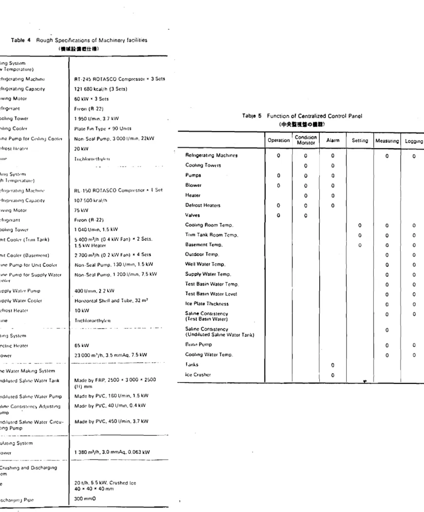
Table 4 gives the general specifications of the machinery facilities, while Photo
4
shows the machinery area.4.2.1 Refrigeration Facilities
Broadly speaking, the refrigeration facilities consist of two main systems. One of these is a cooling system designed to keep the test basin room cold; its ultimate purpose is to promote [and maintain] freezing conditions. (This will hereafter be referred to as the "low-temperature ll cooling system.) The other system has been established in order to precool the well water that is supplied to the test basin and to refrigerate the trim tank room and the basement (hereafter this system will be referred to as the "hfgh-Lemper-a'tur-e" cooling system).
(1) LoW-Temperature Cooling S,ystem
Figure 5 is a diagram of the low-temperature cooling system. A brine-type of refrigeration method has been adopted for this system,
which achieves cooling by means of natural convection brought about by coils installed on the ceiling of the test basin room. As can be seen from the diagram of this system, the "brine pumpll is employed to send brine from the brine tank to the coils on the ceiling. After heat exchange takes place in these coils, the brine is returned to the brine tank through a pipe. The temperature in the test basin room can be controlled over a range of +50
to
-35
0C by altering the temperature of the brine that flows through the
ceiling coils. Plate fin types of coil coolers were selected for the ceiling in view of the amount of frosting that would [otherwise] occur; moreover, since a natural-convection method was adopted, a total of 90 of these coolers were installed in an arrangement that would provide coverage for the entire
16
-making the height [of the ceiling coolers] uniform, positioning them so that the surface of the water in the basin would not be subject to radial or other types of effects originating with the coolers. The temperature of the brine is regulated by causing some of the brine returning from the coils to be diverted by means of a three-way control valve to the suction side of the brine pump, and then mixing this brine in an unchanged form with a given volume of brine sucked in from the brine tank; that is, by adjusting the ratio of the resulting mixture, control can be achieved over the temperature of the brine. For this reason a certain amount of brine is ordinarily kept flowing in the ceiling coils. Bulbs at the inlet and outlet ports of the coils are adjusted to make sure that an equal volume of brine flows through each of the coils. Once the bulbs are properly adjusted, this method ensures that brine can be kept flowing through the coils without the balance among the coils being disrupted by fluctuations in the total volume of brine that is being circulated. A defrost heater (electrical) is installed to remove frost from the ceiling coils, this defrosting action being accomplished by heating only the brine returning from the coils. In this case, that is, the brine within the brine tank is left unheated.
The refrigeration machines that were employed were the RT-245 ROTASCO Compressor models, which are rotary types of refrigerators that give off relatively little vibration. Three of these machines were used. In this refrigeration system, a refrigerant (a superheated steam) that has been compressed in a compressor is cooled in a condenser to produce a supercooled liquid, which first passes into a fluid receptacle and then through an
expansion valve into an evaporator, with the expansion valve serving to reduce the pressure. Heat exchange is effected in the evaporator between [the supercooled liquid and] the primary brine that is circulating between the
brine tank and the evaporator, and [the refrigerant] then vaporizes and is drawn back into the compressor. Control over the volume [of the refrigerant] is achieved by monitoring the temperature of the brine tank and using this information to adjust the degree of opening of a valve on the inlet side of the compressor. Whether the three refrigerating machines are used all in conjunction with one another or operate alone is determined automatically, depending upon the load. Flexible operations are also made possible by the fact that the evaporation temperature can be varied so as to be in
accordance with the "slow-cooling" phase of operations, the initial period during which the temperature gradually shifts from ordinary to cooler levels. The refrigerant employed in these refrigerating machines is Freon (R-22); trichloroethylene has been selected as the brine in view of a number of considerations, including toxicity, propensity to corrode metal, viscosity, evaporation temperature, and cost.
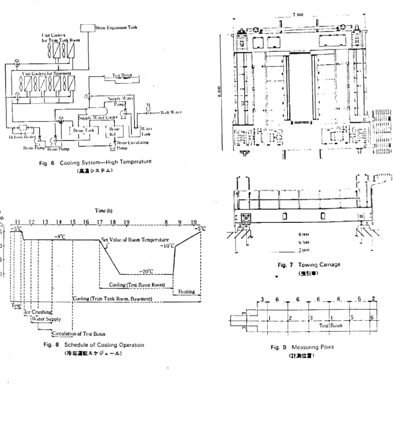
(2) High-Temperature Cooling System
Figure 6 is a diagram of the high-temperature cooling system. As in the low-temperature cooling system, the brine method is used to achieve
refrigeration. This system is utilized to precool the water that is supplied to the test basin, as well as the trim tank room and the basement. To begin with the precooling of the basin's water supply: well water (at approximately 16° C) is drawn up by the supply-water pump and is cooled down to +2° C by being circulated through the supply-water cooler and then back into the water tank. The water that is fed into the test basin is brought up from the water tank and pumped through the above supply-water tank by the same supply-water pump mentioned above. Next, the trim tank room and the basement are
refrigerated using unit coolers (forced-circulation types of fin coils), two of these units being installed to cool the trim tank room and four for the
18
-basement. The temperature in these areas is regulated by using a three-way control valve to cause some of the brine that ordinarily enters the unit coolers to bypass them and go instead into a return pipe; that is to say, temperature control is achieved by adjusting the volume of brine that enters the unit coolers. However, heaters are embedded in the unit coolers that are used in connection with the trim tank, so that the temperature in this room is governed by combining cooling and heating effects, a temperature range of 0° C to 10° C being attainable by regulating the flow of brine and by using the heaters. The basement, though, can only be cooled within the 0° C to 10° C range, so that any increase in temperature in the basement has to be left to the natural course of events. As regards temperature control within the brine piping system, the circulating brine can only be heated, with (electrical) defrost heaters being used for this purpose; by this means frost that accumulates on the plate fin coils can be removed.
The refrigerating machine used in the high-temperature system is a rotary model, the RL-150 ROTASCO Compressor. One is installed. The
refrigerant employed with this machine is Freon (R-22), while the brine is trichloroethylene.
4.2.2 Heating System
This system consists of: a blower that is installed in the machinery room for the purpose of heating the air in the test basin room; an electric heater; and an air duct that connects an exhaust chamber and an intake chamber installed on the· side walls of the test basin room. The
approach adopted for heating the test basin room is to heat the room's air and circulate it; by using this system, the room temperature can be raised from _20° C to 0° C in less than 2 hours. The heating system is intended to make it possible to control the dynamic properties of the ice in the test
basin after the desired degree of freeze-up has been attained. The volume of warm air supplied by this system, as well as the direction in which it is blown, are controlled to ensure that the air does not disturb the ice's
surface by directly hitting it, as this would play havoc with the properties of the ice, and care is also taken to avoid blowing on the ceiling coils and melting the frost that accumulates on them. The blowing chambers are
installed longitudinally to the test basin so as to provide complete coverage of the room, one of the room's side walls being used for the exhaust and the other side wall for the incoming air. MOreover, the outlet and inlet ports of the chambers were carefully arranged so as to be at equivalent positions, thus maintaining a uniform temperature distribution within the room while it is being heated. Control over the room's temperature is aChieved by control-ling the capacity of the electric heater.
4.2.3
Salt Water-Making SystemThis system, which is intended to bring the density of the test basin water to a specified level, is composed of a salt storage tank, a tank that contains concentrated salt water, an circulating pump for concentrated salt water, a salt content* adjusting pump, and a piping system. The concentra-ted salt water tank is made of glass-fiber reinforced plastic and is locaconcentra-ted underground beneath the salt storage tank. Well water and industrial-grade salt are fed into this storage tank and mixed by a stirring pump to produce concentrated salt water. The salt content [of the test basin water] is regulated by first measuring the density of the test basin water with a densitometer and then adjusting the density to the desired level by adding the amount of concentrated salt water that calculations show needs to be added for this purpose. The volume of water [in the test basin] is selected so that [its salt concentration] can be easily adjusted; the concentrated salt
20
-water pump is used to provide the basin with its initial supply of salt water, and the salt content adjusting pump is ordinarily employed to supply salt water during the experiments. These pumps are made of vinyl chloride, while the pipes have a polyethylene lining.
4.2.4 Circulation System
This system is designed to increase the cooling efficiency by forcing the room's air to circulate in the test basin. Air is blown against the ceiling coils by 20 circulators (blowers) installed above the corridors that run alongside the test basin; this air not only accelerates the heat exchange that takes place in the ceiling coils, but also promotes heat transfer
between the [room's] air and the water or ice in the test basin. The circulators are positioned so that they will not prevent convection in the air during the periods when natural convection is relied upon to produce cooling; weather covers are placed on the exhaust side of the circulators to permit adjustment of the air's direction. The circulators, furthermore, can be put to effective use during defrosting periods.
4.2.5 Ice Crushing and Discharging System
This system consists of equipment for breaking up and discharging the chunks of ice that are present in the test basin at the end of an experiment. The ice is broken up only when a plate that is installed at the front of the towing carriage (to be described later) is lowered onto the ice's surface; once the plate has been lowered, the ice sheet is broken up and collected as the towing carriage moves forward. This broken ice falls into a hopper situated at the end of the test basin, where it is divided into finer pieces
by an ice crushing machine that is installed at the bottom of the hopper. These fine ice chips fall into a discharge pipe connected to the bottom of the ice-crushing machine, and then are carried outside of the building by well water, passing through a discharge channel to be ultimately released into a diluting tank. The inner surface of the hopper is covered with
YUS-170 austenitic stainless steel, which has excellent resistance to pitting and abrasion and to attack by salt. The top of the hopper is fitted with an insulated cover to prevent the incursion of heat during refrigerated periods.
4.2.6 Other Equipment (1) Wave-Extinguishing Equipment
A wave-extinguishing device made of stainless steel has been installed on the trim tank side of the test basin.
(2) Equipment for Stirring the Test Basin Water
The test basin water is circulated by a pump in an effort to keep the salt concentration and the water temperature uniform. [The pump], which floats, is inserted into the test basin only when it is being used.
(3) Water-Purification System
The water-purification equipment consists of a floating type of
purifying filter that is carried by a circular tank. The basin's water is purified by the filter while being circulated by a pump, with the filter running on its own as it floats in the basin. The filter element is of the cartridge type and utilizes a special styrene-resin foam. This purifying filter is transferred from the trim tank to the test basin only when it is to be used.
Other equipment is also being employed, including plumbing equipment, an air conditioning system, electrical equipment, communications equipment, sanitary facilities, fire-fighting equipment, and equipment for recovering
22
-brine in case of emergency. An account of these facilities, however, will be omitted here.
4.3
Control systemA centralized control panel is installed in this facility, making it possible to monitor and record when the various machines begin or suspend operation as well as other information, such as the temperatures in the various rooms, water temperatures, etc. This control panel is especially useful in that it permits operations to be carried out automatically overnight, particularly the operations connected with freezing the test basin's water. To begin with, the panel enables the temperature that has been set for the test basin room to be automatically maintained by
controlling the operation of the cooling and heating equipment described above. When the temperature setting for a room needs to be altered - that is, when the change is to be made from a cooling period to a heating period, or from heating to 」ッッャゥイセ - automatic control over such changes is achieved by inputting beforehand into the centralized control panel the room
temperature that is to be attained, in addition to the times that the various machines should be turned on or off and the times that valves should be
switched open or closed. As for the range of settings that can be made vdth this control panel, room temperatures of anywhere between +5° and -35° C can be arranged, and the time schedule for a full week can also be included. At present temperatures are set according to specified times; however, steps have been taken to try to make it possible in the future for temperatures to be controlled by readings of other factors, such as the thickness of the ice sheet. The temperatures in the trim tank room can be regulated through the centralized control panel within a range of 0° to 10° C, the panel causing either the refrigerating or the heating machines to be set into operation.
The room temperature in the basement, too, is governed over a O· to 10· C range by the centralized control panel, but in this case, as mentioned earlier, only cooling can be initiated, as any rise in temperature has to
,
take place naturally there. Control over the temperature of the water that is supplied to the test basin is accomplished by monitoring the temperature [of the water issuing from! the outlet of the supply water cooler and then making a corresponding adjustment in the brine flow rate. The volume of the water entering the test basin is controlled by the supply water pump, which operates automatically in accordance with readings from a water-level meter that has been installed in the trim tank room. The concentration of the salt water is controlled automatically, too. When this water is supplied to the test basin, a measurement is made of its salt content, and then the volume of concentrated salt water that needs to be added to achieve the desired saline level is calculated and automatically [pumped in!. Not only these but other systems, too - e.g., the cooling systems, the cooling tower system; etc. - all operate automatically once they have been started up.
The functions of the centralized control panel are shown in Table 5. A temperature-setting device and a data logging device are included in the control panel, while data processing and time management, etc. are carried out by a microcomputer. The data logger receives analogue signals for 40 points and records 35 of them digitally, taking these points to be a
[representative! selection of the whole.
4.4 The Towing Carriage and Other Equipment
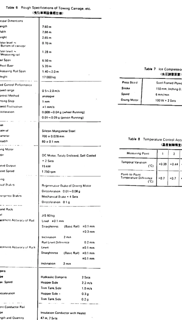
The general specifications of the towing carriage and some other equipment are presented in Table 6.
The towing carriage used in this facility differs in a few respects from those generally used with water tanks. These differences can be summarized
24
-as follows.
(1) The forces that the model ships, etc., are subjected to by the ice are far greater than ordinary hydrodynamic forces; as a result, it is
sometimes difficult for the ships to be moved along the usual types of rails when steel wheels are used.
In
view of this problem, the towing carriage has been equipped with a rack-and-pinion driving system.(2) The towing carriage not only can be operated at ordinary temperatures, but also works under low temperature conditions, down to
-350 C. The towing carriage may be exposed to low temperatures for prolonged
periods of time, especially during experiments on the extrication of [ships] from icy seas. Therefore, all of the electrical equipment used with the carriage is designed to withstand severely cold conditions. In addition, since extreme temperature variations are encountered in these tests, the materials employed are ones that do not experience problems with stress, strain, etc., under such conditions.
DJ
Since salt water is employed in the test basin, consideration was also given to how well materials and paints resist attack by salt when evaluating their possible use.4.4.1 The Towing Carriage
The general layout of the towing carriage is shown in Fig. 7, while Photo 5 shows its appearance. This towing carriage has a box-girder type of structure that makes it easy to preserve work space. At the front of the anterior cross beam is a device for crushing and collecting ice, while a water sprinkler and a hydraulic unit for emergency breaking are installed in the interior of the beam. The posterior cross beam is equipped with a pair of driving mechaniSms. The longitudinal girder has emergency brakes and a speed-monitoring device in its interior, while an operations panel and
various types of controlling boards are installed on its top. Guide rollers are installed at the sides of standard rails at both ends of the longitudinal girder; these serve to prevent meandering as the towing carriage is operated. The span of the measuring rail can be varied within the range of 1.4 to
2.0 m. Weatherproof welded structural steel plates (SMA-4lC) are utilized as the principal strengthening material, and stainless steel is employed for the measuring rail. The towing carriage is moved using either a pinion or a wheel tyPe of running method, with a manually operated clutch being used to switch from one of these methods to the other. Moreover, the rear axles are employed for driving the carriage. As for the electric motor, this is a totally enclosed, self-cooled type of DC motor with a rated output of 15 kW, with the Ward-Leonard system of speed control employing a thyristor being adopted and with control over the rear axles being accomplished by connection in series. Furthermore, in cases where mechanical strength would
be required by a material that was being evaluated for use in the electric motor, .the brittleness of the material at low temperatures was taken into account, and decisions concerning painting, greases, outlet wires, etc., were also made with full consideration being given to the need to ensure
protection from the cold and from corrosion caused by salt. The various panels are special types of insulated cases; their surfaces have been treated to provide resistance to salt attack and space heaters have been installed in their interiors. The control panels are not equipped with the usual sorts of observational and operational instruments; instead, with the exception of observational equipment installed in the operations panel, the control panels were designed so that observations would be made through windows. Photo 6 shows various panels on the towing carriage. Ordinary braking of the towing carriage is by regenerative braking that relies upon the driving motor's
26
-torque, whereas a mechanical rail-catch method is utilized for emergency braking. Hydraulic bumpers* have been installed where the towing carriage's run ends. In addition the facility is equipped with a trolley tower and current collector, supports for the hydraulic bumpers, and so on.
The ice-crushing apparatus installed on the anterior cross beam is ordinarily raised, resting ッセ top of the beam. At the conclusion of an experiment, however, when it is time to break up the ice and remove it, this apparatus is lowered by an elevator device to a certain position, and is then used to rupture the ice sheet, discharge the resulting chunks of ice, and clean up the [water] surface as well. The sprinkling equipment, moreover, is employed for so-called "seeding" purposes: when ice begins to form in the test basin, droplets of water are sprayed out of a nozzle as the towing carriage starts its run. The pump, tank and tubes of this sprinkling system are installed in a unitized form within the [anterior] cross beam, and are warmed by a heater to prevent them from freezing up. Finally, metal surfaces that the experimenters may come into direct contact with while on the towing carriage (surfaces such as the floor, handrails, etc.) have been given a surface treatment so ensure that no problems will arise even if they should be touched with the bare hand under freezing conditions.
4.4.2
Rails and ChairsSixty kilogram rails conforming to Japanese Industrial Standards (J1S) were machined for use in the ice model basin. These rails are not welded together but are connected by cotter bolts, since the inner walls and the upper edges of the test basin are coated with glass-fiber reinforced plastic
*Translator's note: Inference from context; the Japanese term used here means either "bumper" or "damper" (the latter translation is used in Table 6.)
27
-and no pressure welding or ッセィ・イ types of welding operations can be performed within the room. The rack that is employed had been machined and screwed onto a rack base. Since the temperature in the [test basin] room fluctuates rapidly and over a wide range, the rails and rack undergo significant
expansion and contraction. This expansion and contraction can be transmitted through the chairs to the concrete body of the test basin, subjecting to excessive and repeated loads. Consequently, in order to prevent this from happening, active Teflon materials have been inserted between the rigid
surfaces of the chairs and the rails and racks. The chairs are fastened onto the base plate with four stud bolts (used in conjunction with vertical adjust screws). The chair pitch is 800 mm, with the controlling chairs being
displaced by one-half pitch and arranged in a zigzag pattern. Stainless steel was employed in making the base plate, which is suspended* from the FRP-finished upper edge [of the test basin] and secured by anchor bolts, with openings being touched up using non-shrinking mortar and caulking materials. Chemical anchors were for the anchor bolts, which were installed so as not to come into contact with the reinforcing materials distributed within the
concrete body of the test basin. This precaution was taken in order to prevent the low temperatures within the room from being transmitted to the interior of the concrete body, as this would give rise to freezing and thawing action within the concrete.
4.4.3 Current-Conductor Rails**
Seven [current-conductor rails] (440 V - triple phase, 220 V - single phase, 110 V - single phase) covered with an insulator were employed. In
*Translator's note: Inference; literally, "allowed to float". **Translator's note: Here, and in all other passages translated as "current-conductor rails", the text literally says "trolley". "Current-conductor rails" appears in Table 6 but not in the text itself.
28
-order to prevent frost accumulation, heaters were installed within the trolley. The heaters that were used in the trolley were designed after experiments had been carried out to investigate the amount of frost that accumulated on the [current-conductor rails] in the test basin room. Since the test basin room is separated from the trim tank room by a sliding type of insulating door, the [current-conductor railsl are interrupted at that area. However, care has been taken to ensure that there will no problems concern-ing the towconcern-ing carriage's movement and the supply of electricity when this discontinuous section of the [current-conductor railsl is being passed.
4.5
Ice Compression ApparatusThis equipment enables the horizontal pressure on the frozen sheet of ice within the test basin to be increased through the use of press boards that have been installed on the side walls of the basin. The motor-driven press boards have a stroke of 150 mm, and inching is also possible with this equipment, which can be operated more or less independently. Since this apparatus is only used when necessary, depending upon the needs of an
experiment, it has been designed so that it can be easily removed. Table 7 shows the general specifications of the ice-compression apparatus.
5. Outline of the Calculation of Refrigerating Capacity
(1) The temperature of the test basin room depends upon the amount of heat coming into the room from outside and on the amount of heat that leaves the room through the ceiling coils. The amount of heat taken out of the room by means of the ceiling coils is referred to as the refrigerating capacity, while the amount of heat entering the room is called the heat load. This latter value, which is calculated first, can be classified as follows.
(a) Building Load. This refers to the amount of heat penetrating into the room through the insulating materials on the room's walls, ceiling, etc. This value will vary in accordance with the difference between the room's temperature and the outside air.
(b) Freezing 'Load. This refers to the amount of heat [entering the room] when the surface of the test basin is freezing up. This value will depend upon the salt concentration in the basin's water, the room tempera-ture, and the thickness of the ice.
(c) The amount of heat transfer occurring when moisture evaporates into the room from the surface of the ice or water in the test basin.
(d) The amount of heat flowing into the test basin water from the concrete beneath the basin. This value is equivalent to the amount of heat entering the room through the test basin.
(e) The amount of heat required for the objects that are exposed to the air in the test basin room to also be cooled as the room temperature
declines.
(2) Next, calculations are made of the heat transfer that occurs in the ceiling coils. These ceiling coils are part of a system in which brine is made to acquire heat so that a room's temperature will be lovreredj the heat exchange that takes place in the ceiling coils will be a function of the temperature of the brine inside them, the room temperature, and the
heat-transfer area. Or, to put it another way, the brine temperature that will be required in the ceiling coils can be determined from these
calculations.
(3) Then the refrigerating capacity is determined. This value will
depend upon the evaporation temperature and the condensation temperature of the イ・ヲイゥァ・セ。ョエN Now, since the evaporation temperature will be determined
30
-by the need to keep the brine's temperature at a given level, as discussed above, this latter consideration will also be a factor in determining the refrigerating capacity.
(4)
In
addition, calculations are made concerning pressure losses, etc., affecting the auxiliary machinery, tanks and piping. Pressure loss will especially affect estimates of pumping power, which is important as pumps are responsible for bringing about the heating of the brine (and thus [pressure loss lead to] reduced refrigerating capacity).6. Operation of the Facility 6.1 Schedule of Operations
The operations schedule for the testing has been drawn up so that six weeks represents one cycle. Figure 8 provides an example of how the
temperature varies in the test basin room during a phase of the operations schedule that is normally repeated on a daily basis.
6.2 Control of Ice Quality
The ice that is produced in the test basin has to have dynamic properties that are commensurate with the scale of the model ships.
Nevertheless, this is not necessarily easy to arrange. Although salt water is used to form the ice in the test basin, the quality of the ice can still vary depending upon the concentration of salt in the water, the temperature at which the water freezes, and the particulars of the freezing process. The salt concentration is ordinarily adjusted to a given level by [pumping] into the test basin concentrated salt water that has been produced in the
concentrated salt water tank; however, fine adjustments can be made in the salt concentration when the supply water is being fed in the usual manner into the test basin, provided that the salt content is being monitored (and a stirring apparatus is also operating) at this time.
In
order to vary thefreezing process, the room temperature can be abruptly raised using a closed-cycle heating apparatus; or, even though the use of a circulator to induce forced circulation can lead to reduced uniformity in ice thickness, it can also serve to promote heat transfer between the air and the ice and water in the basin. Moreover, the sprinkling equipment on the towing carriage can also be employed to control the grain size of the ice crystals, etc., making it possible to adjust the physical properties of the ice to a variety of specifications.
6.3
Control of Ice ThicknessSince the ice's thickness at a given salt concentration will be a
function of time and the room's temperature, control of the thickness of the ice in the test basin, at least at present (as discussed above), depends upon [control panelI settings of these latter two values. Now room temperature variations also have a direct influence on the quality of the ice; thus, if optimum control over the room temperature is to be achieved, it is essential that careful consideration also be given to the question of the ice's quality when preparing an ice sheet of a given thickness. It is hoped that the
data that will be acquired through the work being done in this facility will make it possible in the future to achieve a greater degree of control over both the quality and the thickness of ice [used in model experimentsl.
7. Data Acquired on the Facility's Operations 7.1 Accuracy of Temperature Control
The temperature in the test basin room varies from +50 to -350 C, and the error in the temperature setting can be stably controlled to within
O
44
0 C as can be seen in Table 8.セ
.
,
Furthermore, as Table 8 also shows, thetemperature within the test basin room [at a given timeI shows a statistical variation within the range +0.70
32
-of the insulating door and 0.5 m above the basic water level. The positions within the test basin room where the measurements were made are shown in Fig. 9. In the trim tank room temperatures vary from 00
to 100
C, and the statistical variation in room temperature has been found to be
+1.3
0C. All of these values fully satisfy the basic requirements for the facility.
The heating system can raise the temperature in the test basin from _200 C to
00 C within
1.6 hours. The refrigerating system used to cool the water that is fed into the test basin has the capacity to provide 8.1 cubic meters per hour of 50 C water when the original well water had a temperature of 160
C.
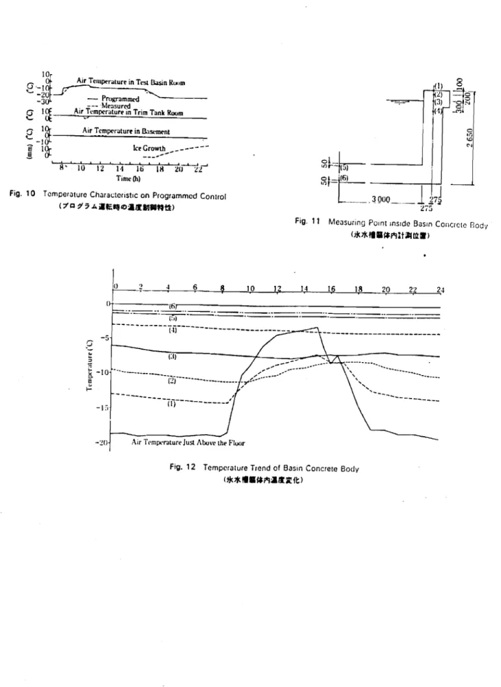
7.2 Characteristics of Temperature Control
The air temperature in the test basin room can be freely controlled by programming the time and temperature input for the cooling control system. Figure 10 illustrates how well the air temperatures in the test basin room, trim tank room and basement can be controlled by such programming. Although the discrepancy that was found between programmed and measured values during the heating process can be bridged by increasing the heating capacity, the values observed here are considered to be satisfactory, taking into account
[effects due to] the melting of accumulated frost and the actual conditions under which the system is used. Furthermore, some of the discrepancy in the measurements for the air temperature in the trim tank room is attributable to opening and closing of the insulating door, which was done to simulate testing conditions.
7.3 Temperatures Within the Concrete Body of the Test Basin
A thermocouple was used to measure the temperatures within the concrete body of the test basin during cooling periods and periods when the [air]
temperature was rising. The positions where measurements were taken are shown in Fig. 11, while Fig. 12 presents the results that were obtained. Measuring position (1) represents the temperature directly below the FRP layer at the upper edge of the side walls of the basin. As for positions (3) through (6), where [the temperature] will have an influence on the freezing process, little temperature variation was found. Figure 13 shows the
temperature variation observed in the concrete body of the test basin over a lO-day period when operations were repeated everyday (with the exception of Saturday and Sunday) following the same schedule. According to the data in this figure, the temperature at measuring position (6) remained constant throughout the period, except for the time when the operations were begun; and this was true in spite of the fact that cooling operations had been suspended on the Saturday and Sunday in the middle of the trial.
7.4
Freezing SpeedIn a test basin having an adequately insulated structure, the speed of an ice sheet's growth will be a function of the water temperature, the room temperature, the salt content of the water, and the relative positioning of the ceiling coils. Basically, however, the rate of freezing will be governed by the transfer of heat between, on the one hand, the room's air and the basin's water and ice, and, on the other hand, between the water and the ice themselves.
The freezing time T(h) that is required to obtain a given ice thickness (h) is expressed by the following equation:
J.
,II eidhT(h)= 1
h)
C• (-;;.,. Ai (d.-tl..) - S
where
0(= the rate of heat transfer within the cold air
34
-•
fA,
=
the density of the iceAi.-
=
the rate of heat transfer in the icettl" ;::
the temperature at the boundary between the ice and waterf)t:t.
=
the air temperaturec
=
the amount of heat flowing in from the test basin's wallss
=
the area of the walls and bottom of the test basinFigures 14 and 15 provide examples of measurements made on the growth speed of ice sheets. In each case shown the salt concentration in the water
was J)
%"
and the air temperature in the test basin room was _200C. The [thickness of the ice sheetl attained a constant level by エセ・ third day after
cooling had begun, although it should be noted in this connection that
control over the temperature in the basement played a large part in obtaining this result. It was also found that the use of circulators to provide forced convection does speed up the freezing process, but at the expense of uniform-ity in the ice's thickness.
Postscript
It has been shown that sheets of ice that exhibit highly uniform
thickness and properties can be prepared within a test basin, and these ice sheets, moreover, fully satisfy the requirements [for model experimentsl. Judging from the functions and capabilities that have been discussed here, we can say that this facility makes it possible to achieve control over a
broader range of temperatures than previous types of ice model basins, and it also enables not only the thickness of the ice but its dynamic properties as well to be varied over a wide range.
This facility has already embarked upon regular operations, with experiments being conducted on a continuing, daily basis. There are an enormous number of research topics that must be clarified, and it is hoped
that the results of the investigations carried out in this facility will in the near future give birth to new ships suited for navigation in icy seas.
In conclusion, [the authors, on behalf of the Systems Engineering
Division], wish to express their gratitude to the Kanto Regional Construction Bureau of the Ministry of Construction for overseeing the construction of this facility to ensure that the design was properly implemented, and sincere thanks are also due to the various personnel at the Ship Research Institute of the Ministry of Transportation who kindly provided technical advice from the user's standpoint. Deep appreciation is felt, too, for the cooperation that the Mitsui Construction Co., Ltd., as well as many manufacturers and dealers involved with machinery and other equipment, provided with respect to civil engineering and construction aspects of the project. Finally, we are thankful for the assistance given by the head and other personnel of the Nagashima Heat-Transfer Laboratory of 1litsui's Nagano Research Institute.
36
-TABLES, FIGURES AND PHOTOS
Table 1 Principal Specifications of Building&Test Basin
(• •RtJC7k1l*,*0;1;JHll
-
MMMMMMMMMセMGM」MZャ
BUilding Area Main BuilC:ing 1.353.68 m!
Saline Storage 14.17m!
Total 1."368.85 m'
Total Floor Area 1.366.41 m!
MaXimum Height GL+9.44 m
BUilding Structure Superstructure Steel Framed Construction
ALC Plate
PC Plate
Substructure Reinforced Concrete Construction
Test Basin Mam Structure Reinforced Concrete Construction
Structure (Water Tight Concrete)
Upper Part Steel Fiber Reinforced Concrete
Saline Storage Concrete Block Construction
Structure
Table 2 Physical Properties 01Insula lion Matcnals
(1Jil!At:t
°
Ult!tfillMaterial Urethane- Rockwool
I
GlassI
Polystyreneloam foam Wool Thermal Conductivity 0.017 0.034 0.038 0.032 0079 kcal/mh'C M M M セ M M M M M Coefficient Spray 1.0of Water Larmnate large large 1-2
AbsorptIon Board less
vol'll. than 1.0
_._-Vapor Spray 1.0
Permeance Laminate
-
65 70 1-3g/m!hmmHg Board 0
Table 3 cィセiャ|GB of Thermal Conducuvitv uf Urethancfoarn (7カセ[NNN 7"-.l.0Mfi:;i.!Jl$!0i:ftl
--- --
-Thermal Conducuvtv
at Low Temperature 0016/O"C 0.018/-25'C 0.019/-50·C
Secular Change 01 Therma' Conouctivuv
(Tretnanetoarn
0014_ 00175-
Table 4 RoughSpocihcations of Machinory facilities (."IQII&lftll) ,ling Svstern IVTemperature) dflgcratlOg Machine cfrlgcratlngCap.lclly IflvmgMOlor .oohnq Tower ..PIlingCooler
.nno Pump for Ct'llLntJ Coou-r
Jefrostl't'Jlt"( '11IHlsケセャャャュ '.Jh Tpm"H'I;JIUll') )rl\llngMotor .oohnqfOWL" .Jmt Cool,',(T"'" Tallk) JnltCooler (Basernoru) -innc Pump for Unit Cooler irlnf1 Pump for Supplywセャエ」イ
,-(loll"
;upplyvjセi{iGイ Pump
;uprly Wale, Cooler
.Jnno
.lccu.c Ht"JtCf
Jlowcr
',ne Waler Mak,ng System
.JndrlurodSaline WaiN Tallk
.Jndrtuted Saline WiJlCr Pump ;,lhnf' COfl51Slt'IlC," AdJustl'lU
llump .
Jndrlutcd Saline Waler Cucu-Jllng Pump
G」オャセャエャョァ System
JIOWCf
• Crushll1g and Dlschargll1g
stem .ce
RT-245 ROTASCO Compressor' 3 Sets 121 680 kcal/h (3 Sets)
60 kW •3SCIS
F,,'oll (R·22) 1950 I/m,n, 3.7 kW
PlatoFII1 Type' 90 Unlls
Non·Seal Pump. 3 000I/m,n.22kW
20kW
IflChlOf(ll'lhyll'll
RL·150 ROTASCO Compressor>1Sel
107500 kral/h 75kW Freon (A 22) 1 040 I/mln. 1,5 kW 5400 m'/h(0 4 kW Fan) • 2 Sets, 1.5 kW Healer 2 700m'/h(02 kW Fan) • 4 Sets Non-SealPump,1301/m,n.l.5kW
Non-ScatPump,1200l/rnin.7.5 kW
400 I/nlln. 2.2 kW
HOflIOn!JI Shell and Tube. 32 m' 10kW Tri」ゥャャッイオセセQ ィケィセョ 65kW 23000m'/h.3.5 mmAq. 7.5 kW MJde by FRP. 2500 • 3 000' 2500 (II)mm Made by PVC. 1801/m'n.l.5kW Made by pvC. 40 t/rmn. 0.4 kW Made by PVC, 450 I/min. 3.7 kW 1 380 m'/h, 3.0 mmAq. 0.063 kW 20 t/h, 5 5 kW. Crushed Ice 40'40' 40 mrn 300 mmO
Tab,e 5 Function of Centralized Control Panel
H・ーセャiエiNioNBI
Operation CondllionMonitor Alarm Selling Measuring Logging
Refflgeratong Machll1cs 0 a 0 0 0
Coo long Tewers 0 a
Pumps a a a
Blower a 0 a
Healer a 0
I
Defrost Heaters a a 0
Valves a 0
Cooling Room Temp. 0 a a
TnrnTank Room Temp. a 0 a
Basement Temp. 0 0 a
Outdoor Temp. a a
Well Water Temp. 0 a
Supply Water Temp. 0 a
Test Basin Water Temp. 0 a
Test Basin Waler Level 0 a
lee Plate Thickness a a
Sahne Consistency a a
(Tes]Basm Waler)
SahneConsistency a
(Undiluted Saline Water Tank)
0111\.'Pump 0 a
Cooling Water Temp. a a
I.lnks 0
Ice Crusher 0
I
SteelFramed Plywood, 9 100 x 200 mm 150 mm. Inching 0.5 mm
6 mm/mln
100 Wx2Sels
Tab/. 7 Icc Compression Apparatus HJeezNiuセゥiI
Table 8 Temperature Control Accuracy of Cooling Room
(aIlItJ...!!) PressBoald Slroke Measuring POint 1 2
I
3I
4I
5 6 Temporal Variation +0.39 +0.44 +038 +0.4/ +0.35 +0 ('C).,-
' 1 , -Pomt-to-Pcmt +051 +0.7 Temperature Dlffl'wncr. +0.7 +0.7 +04 +0.6 rei 38 -:0.1mm 2 Sets 2.2 m/s 1.0 mls 0.3 g 0.2 g 0.2mm :0.1 mm (BaSIC RaIl) :0.1mm 2min 7.60m 7.66 m 2.65 m 070m Inclination 2min R.J1' LevelD.lf"ft'ncc JIS 60 kg Lovel :01mmStralghlness (BaSIC Rail) :0.1 mm
±0.3mm
1.28m
6.50m
rエGァ|セiwイjエャカャG OJ,)k"ofDflvrngMotal
Dccceterancn 0.01-0.06 g
MechanicalOlakc • 4Sees
OeccctcratIon 0 1 9
Slhcon Manganese Steel 700 : 0.028 mm 80: 0.1 mm 520nI t5kW I750 rpm 05-2.0 mrs t.40-2.0m 17000kq
DCMUIO., TOl3lyEnclosed.Sell·Cooled • 2 Sets
analogue
1 mm :1 mm/s
0.008 -0.04 g (wheel Running)
O.Ot -0.09 q(puuonRunning)
LEU/It'. Straightness InchnaCion HydtauhcDampers Hoppe, Side TnmTan" Side Hoppe, Side • TnmTank Srde
Insulation Conductor with Heater
47m. 7 St-Is
Type
Length and QuantIty
Oecceter anon
Placpnwnl Accu,acy of Rack
Type Ma•. Speed Typ" Malenal Rated Speed Welgln Breadlh water level -Bottom of catrl.1Qt' Water levd -Measuflng rar!
Table 6 Rough Specifrcauons of Towing Cartlage. etc.
HAャセiNwg。ャャャZヲᄆNI Lenglh Width HeIght Rail Span Wheel
Bas.-Measullng RaIlSpan
Speed ControtpーイヲッイャtャセQョ」エャ Speed range Control Method 5f'lIIng Step SpeedFluctUJI1UI1 Dmnng Motor Wheel
Rail and Rack. Rat!
Ptacement Accu. acy of Rail BrakIng
USUJIBI.J"-I'S
Dampers
セMMMMMMMMMMMMMMMM
,igeWin ow,
Test Basin
0 0 0 0 0 0 0 0
Vertical Door Underwater Windows
Rail Undiluted Saline I Wall'rTK. ,. -l ,
---,
B----:
t__
=_u_m___
...
LセセセZ⦅ェヲZQ
i Cooling Towerセ -: JFig, 1 General Arrangement
(-lilf.> 12200 12 iOO 53800 Office 'Y' TrimTankRGOm GL Observation Corridor Hopper Fig. 2 Section 1 (l/iiii1) Fig. 3 Section 2 (l/iiii2)
.
BGセエセQ I' ! , - - -, _._... .---- ----._---t-. - .ru
-fセ]Mセr:=::-
=1 I jI' Tro ley Cl'Ilmll (".Ias
I G,,,,"'
Iャャセャ
.
C,.,"", R,.mセ
Huom \\ indow " IrI I Duct" セa ' エMセRッキゥイゥセセイゥ[ZャG ____ . ,L Tr.uks and Slt-qll'rS '..b. L L -r - - - . . . ....-セ " l'olvurcthane Tl'slIkisin Side [l
Insll!;llulfl f\.!t1l1l1\\'indow
....
\Vidow:/ IV I IlaSl'ml'nl.1 fセMMMMMMゥ セ " , lOhSl·r'v。セtョ
.
Corridor) "" GセGiAヲZQj *.l::Fig, 4 Sectionof Test Basm (;k
*
1I:i:iii illPFig, 5 Cooling System-Low Temperature
40 -7U)t) iイZNセ u
R"';'\
, セr
--o
60UOFig. 7 Towing Carnage
HAャセiNI
..
_ _ _ _,RjNセゥョ 10 '-S·C \I HイlMM||セGQャ \\till ,CoolinR(TestItlsinRoom)
!
セセセセセMMMMMMMMM⦅N⦅セ , TillU'(h) 1,5 1,6 1,7 iセ 1,4 Ilril1l'eクーゥャョセゥオョ Tank
Fig. 6 Cooling System-High Temperature (;a;a-;;A7 A) " , :セ :|MセセMBBtBBGZG[GMBMMLNMMMMMNNウNNᄋエ Valuo ,,111,xlm Temperature I , I ' -IO'C : : I : ::
:
::: :
i
I' I I I I t I " , I ' I I 1; : : : : : I::
:, :' I I I I I:: :: : ,CexllinR(TrimTankRoom. Basement) ___
fI I -tセZ
.'
I : セ cセオウィゥョャg : ZZ|Gセエ・イ Supply : , , '----, !:firculation01TestB..sin
-10 -5 -20 -15 t'stlbsin ,lOrnTemp. ('C)
Fig. 8 Schedule 01 Cooling Operation (]f;tillilfi;A7";; '"-Jl.)
Fig. 9 Measunng Point (IUltlt81
Air Telllperaturein Test BasinRt>,m
Air Temperaturein B"sclllt'ni
keGrowth
_---
---,---Fig. 10 Temperature Characteristic on Programmed Conlrol
<;I'cセZW AゥiセBPBセFii ..fttt)
Fig. 11 Measuring POlOt msrdo Basin Concreto fJodv
<**..
8f*r*litJllllt.> o 10 12, 1,4 16 I!I 2,0 24 '-;,':--- .. , '''..
'--- --- . --- --- ..セオMMMM . ._ _ .. . . .._ _u _ N⦅MMMセN⦅MMMMM⦅N__
._-_._-_._-_._-_._-_._-MMMMMMMMMMMセヲゥMMMMMM --- , ---(71)---' -5 o"--:!O Air Temperature Just Abovethe Floor
Fig. 12 Temperature Trend of Basin Concrete Body