HAL Id: hal-00806076
https://hal.archives-ouvertes.fr/hal-00806076
Submitted on 29 Mar 2013
HAL is a multi-disciplinary open access
archive for the deposit and dissemination of
sci-entific research documents, whether they are
pub-lished or not. The documents may come from
teaching and research institutions in France or
abroad, or from public or private research centers.
L’archive ouverte pluridisciplinaire HAL, est
destinée au dépôt et à la diffusion de documents
scientifiques de niveau recherche, publiés ou non,
émanant des établissements d’enseignement et de
recherche français ou étrangers, des laboratoires
publics ou privés.
Elaboration and characterization of Fe1-xO thin films
sputter deposited from magnetite target
Bruno Mauvernay, Lionel Presmanes, Stéphanie Capdeville, Valdirene
Gonzaga de Resende, Eddy de Grave, Corine Bonningue, Philippe Tailhades
To cite this version:
Bruno Mauvernay, Lionel Presmanes, Stéphanie Capdeville, Valdirene Gonzaga de Resende, Eddy de
Grave, et al.. Elaboration and characterization of Fe1-xO thin films sputter deposited from magnetite
target. Thin Solid Films, Elsevier, 2007, vol. 515, pp. 6532-6536. �10.1016/j.tsf.2006.11.131�.
�hal-00806076�
O
pen
A
rchive
T
oulouse
A
rchive
O
uverte (
OATAO
)
OATAO is an open access repository that collects the work of Toulouse researchers and
makes it freely available over the web where possible.
This is an author-deposited version published in:
http://oatao.univ-toulouse.fr/
Eprints ID : 2428
To link to this article :
URL :
http://dx.doi.org/10.1016/j.tsf.2006.11.131
To cite this version :
Mauvernay, B. and Presmanes, Lionel and Capdeville, S.
and De Resende, V.G and De Grave, E. and Bonningue, Corine and Tailhades,
Philippe ( 2007)
Elaboration and characterization of Fe1–xO thin films sputter
deposited from magnetite target.
Thin Solid Films, vol. 515 (n° 16). pp.
6532-6536. ISSN 0040-6090
Any correspondence concerning this service should be sent to the repository
administrator:
[email protected]
Elaboration and characterization of Fe
1
–x
O thin films sputter
deposited from magnetite target
B. Mauvernay
a, L. Presmanes
a,⁎
, S. Capdeville
a, V.G. de Resende
b, E. De Grave
b,
C. Bonningue
a, Ph. Tailhades
aaCIRIMAT UMR CNRS 5085, Université Paul Sabatier, 118 Route de Narbonne, 31062 Toulouse Cedex 9, France bNUMAT, Department of Subatomic and Radiation Physics, University of Ghent, Proeftuinstraat 86, B-9000 Gent, Belgium
Abstract
Majority of the authors report elaboration of iron oxide thin films by reactive magnetron sputtering from an iron target with Ar–O2gas mixture.
Instead of using the reactive sputtering of a metallic target we report here the preparation of Fe1–xO thin films, directly sputtered from a magnetite target in
a pure argon gas flow with a bias power applied. This oxide is generally obtained at very low partial oxygen pressure and high temperature. We showed that bias sputtering which can be controlled very easily can lead to reducing conditions during deposition of oxide thin film on simple glass substrates. The proportion of wustite was directly adjusted by modifying the power of the substrate polarization. Atomic force microscopy was used to observe these nanostructured layers. Mössbauer measurements and electrical properties versus bias polarization and annealing temperature are also reported.
Keywords: Iron oxide; Sputtering; Electrical properties and measurements; Mössbauer spectroscopy
1. Introduction
The preparation of iron oxide thin films can lead to devices with attractive optical, magnetic, and semiconducting properties, which can be tailored by the parameters of preparation. Among all the processes for producing films, the sputtering process is one of the most popular. This method allows film preparation at moderate temperatures, making it possible to deposit on various substrates with high homogeneity and good uniformity. As a consequence, the sputtering technique is widely used in research laboratories as well as in industrial production units.
The majority of authors active in the field of iron oxide thin films, reports the elaboration of such films by reactive magnetron sputtering from a Fe target applying an Ar–O2gas mixture[1–3].
The proportion of oxygen present in the plasma then determines the stoichiometry of the oxide. However the control of this chemical reaction is quite difficult. A convenient method to obtain substituted-ferrite thin films is by radio frequency (RF) sputtering of a mixed ferrite target[4–6]. Physical and chemical properties of as-such grown films are highly dependent on the sputtering
conditions (argon pressure, RF power, target/substrate distance, magnetron…). These sputtering conditions act on the energy and on the angle of incidence of the particles that are ejected from the target
[7,8]and consequently act on the film growth and microstructure.
During sputtering, the layer growing on the substrate is sub-jected to continuous bombardment by energetic species emitted from the target or retro-diffused. In the case of oxide deposition, oxygen atoms can even be ejected from the film when the bombardment becomes stronger[9,10]. These extreme conditions of preparation lead to interesting reducing preparation conditions from which non-stoichiometric or out-of-equilibrium oxides can result[11,12].
As for the sputter deposition of wustite thin films, most authors
[3,13–15]attempted to use reactive magnetron sputtering from a Fe
target. However, upon increasing oxygen content, different phases ranging fromα-Fe to Fe1–xO, Fe3O4, andα-Fe2O3, were obtained.
Only Peng et al.[16]mentioned the possibility of obtaining wustite thin film directly from an oxide target and without bias for the high RF power applied to the target. They also succeeded in changing the Fe2O3/Fe3O4ratio by using bias polarization.
Instead of using reactive sputtering from a metallic target, the present authors produced Fe1–xO containing thin films by direct
sputtering from a magnetite target in a pure argon gas flow with ⁎ Corresponding author. Tel.: +33 5 61 55 81 03; fax: +33 5 61 55 61 63.
E-mail address:[email protected]_tlse.fr(L. Presmanes).
applied bias power. In this report, they present and discuss the influence of substrate polarization on the proportion of wustite in the as-such obtained films and the consequences of this proportion on the electrical properties of the films.
2. Experimental details
Iron oxide thin films were prepared by RF-sputtering method using a pure Fe3O4ceramic target. The apparatus is an Alcatel
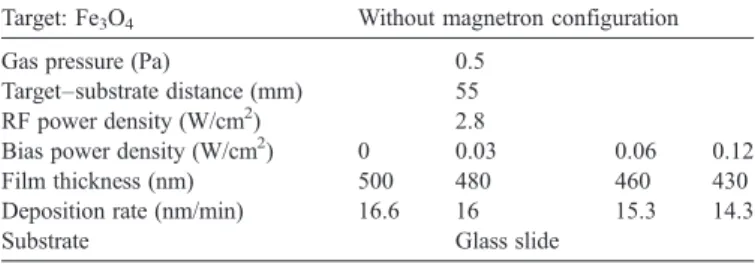
SCR650 equipped with an RF generator (13.56 MHz), and a pumping system composed of a mechanical pump coupled with a turbo molecular pump. A residual vacuum of 5 × 10− 5Pa was reached in the sputtering chamber before introducing the deposition gas. The films were deposited on glass slides for all studies. The distance between the target and the substrates was 55 mm and the power density applied to the magnetite target was 2.8 W/cm2. Different RF bias power densities from 0 to 0.12 W/cm2were also applied to the substrate. The gas used in this study was argon and the working pressure was kept at a value of 0.5 Pa. The conditions of deposition are summarized in
Table 1.
Film thicknesses were measured using a Dektak 3030ST profilometer. Structural characterizations of the films were performed by glancing incidence X-ray diffraction (XRD) on a Siemens D5000 diffractometer. Morphology and microstructure of the as-deposited samples were examined by atomic force microscopy (AFM), performed on a Veeco D3000 system. The resistivity was determined on the as-deposited and annealed samples with a QuadPro four-point probe device from Signatone equipped with a Keithley SMU 237. A selected thin-film sample was also examined by57Fe Mössbauer spectroscopy at room temperature (RT). Mössbauer spectra (MS) in transmission geometry and with two different velocity increments per channel, i.e., ∼0.045 mm/s and ∼0.015 mm/s, respectively, were recorded with a 57Co (Rh) source using a conventional time-mode spectrometer with a constant-acceleration drive and a triangular-reference signal. Accumulation of the data was performed in 1024 channels until a background of at least 106 counts per channel was reached. The spectrometer was cali-brated by collecting at RT the MS of a standardα-Fe foil and the isomer-shift values quoted hereafter are with reference to this standard. The absorbers consisted of a stack of four thin glass substrates (0.1 mm), with on each side a film of thickness 300 nm. The spectra were analysed assuming symmetrical components with Lorentzian line shapes.
3. Results and discussion
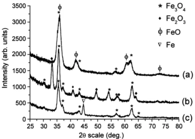
Iron oxide thin films were deposited with variable bias polarization applied during film growth. The conditions of preparation are reported in the Table 1. The thickness of the coating was not drastically affected by the substrate polariza-tion. When the RF polarization applied to the substrate varied from 0 to 0.12 W/cm2, the thickness decreased from 500 nm to 430 nm. Fig. 1shows X-ray diffraction patterns of the biased and nonbiased thin films. When no bias was applied to the growing film, the XRD pattern of the obtained product showed a pure Fe3O4iron oxide with a well-defined spinel structure
(Fig. 1a). When the substrate was polarized, a loss of oxygen in
the growing film might be induced by the strong bombardment by high-energy incident Ar+ cations. Fig. 1 reveals that the applied bias polarization gradually leads to the formation of a reduced phase Fe1–xO. A mixture of Fe3O4with Fe1–xO was
deposited when the substrate was polarized with 0.03 W/cm2, while a pure wustite phase according to XRD was obtained by increasing the bias power density up to 0.06 W/cm2. Finally, for the highest polarization that we applied to the substrate (0.12 W/ cm2), α-Fe mixed with Fe1–xO iron oxide was formed.
Temperature during the deposition process was not probed in situ, but the glass substrate did not melt which proves that temperature did not exceed 500 °C. Normally wustite is not formed at such low temperature. The oxygen stoichiometry of the iron oxide depends on temperature and on oxygen partial pressure. For example in the literature it is claimed that bulk FeO can be prepared from a hematite and iron mixture in evacuated and sealed vitreous silica tubes at 1273 K[17,18].
According to the XRD patterns it is clear that the stoichi-ometry of the thin film can be controlled by simply adjusting the bias power. The polarization of the substrate acts as a key parameter to move into the phase diagram of Fe–O.
Fig. 2shows the electrical resistivity of“as-deposited” thin
films versus the applied RF bias power density. The evolution of the resistivity proceeds along three tendencies. First, the resistivity decreases from 0.045Ωcm to 0.035 Ωcm when bias power density increases from zero to 0.03 W/cm2. XRD has shown that for 0.03 W/cm2 bias power density a significant Table 1
Sputtering parameters
Target: Fe3O4 Without magnetron configuration
Gas pressure (Pa) 0.5
Target–substrate distance (mm) 55
RF power density (W/cm2) 2.8
Bias power density (W/cm2) 0 0.03 0.06 0.12
Film thickness (nm) 500 480 460 430
Deposition rate (nm/min) 16.6 16 15.3 14.3
Substrate Glass slide
Fig. 1. X-ray diffraction patterns for thin films deposited with different bias power density, (a) 0 W/cm2, (b) 0.03 W/cm2, (c) 0.06 W/cm2, and (d) 0.12 W/cm2.
amount of Fe1–xO phase precipitated within Fe3O4. This feature
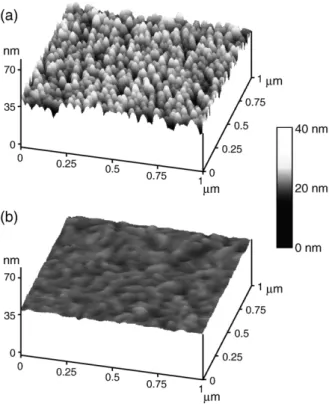
would normally lead to an increase of the RT resistivity due to the contribution of the wustite[19]being lower than magnetite. It is therefore suggested that the decrease of the resistivity for the lowest value of bias power density is related to the densification of the thin film due to the Ar+bombardment. It is indeed well known that bias sputtering can densify as well as planarize the growing film. The decrease of the resistivity as a result of this densification would then over-compensate the increase due to the precipitation of wustite in the magnetite matrix. The AFM images of 300 nm thin film deposited without any bias and with 0.02 W/cm2are presented in theFig. 3a and b, respectively. The
densification can be clearly observed. The average roughness of non-biased film is close to 2.9 nm, whereas it drastically lowers to a value of 0.6 nm when the substrate is exposed to 0.02 W/cm2 bias power density during the deposition process. The steep increase of resistivity in the second part of the curve can be attributed to the strong increase of wustite proportion for higher bias density. According to the X-ray diffraction pattern re-produced in theFig. 1, the reduction of the spinel ferrite into wustite phase is nearly complete at 0.06 W/cm2. Stress and implantation of inert gas in the deposited films may also contribute in the increase of resistivity. Finally, when bias power density increase up to 0.06 W/cm2, a new slight lowering in resistivity is observed again. The phenomena can be related to the appearance of metallicα-Fe with a much weaker resistivity than the involved oxide phases.
A room-temperature Mössbauer spectrum for a sample deposited with the same sputtering conditions as sample (c) of
Fig. 1(0.06 W/cm2bias power density) was initially acquired in
the source-velocity range ± 11 mm/s (Fig. 4a). It is clearly com-posed of a major central absorption and a very broad sextet. Fitting this spectrum with a Lorentzian-shaped sextet and two unconstraint quadrupole doublets to phenomenologically ac-count for the central absorption, revealed that approximately Fig. 3. AFM images (1 × 1μm2) of 300 nm thin films deposited (a) without any
bias and (b) with 0.02 W/cm2bias power density.
Fig. 4. Mössbauer spectrum measured at room temperature of a 500 nm thin film deposited with 0.06 W/cm2 bias power density recorded in the velocity
range (a) ± 11 mm/s, and (b) ± 4 mm/s. Fig. 2. Electrical resistivity of“as-deposited” thin films versus the applied RF
20% of the Fe species is responsible for the magnetic component. Although XRD measurement had showed only one crystalline phase, Mössbauer spectroscopy brings to the fore that this sample is not pure and composed for more than one phase. The nature of the Fe phase giving rise to this latter component could not be assessed from the obtained fit results. In a next stage, a spectrum for the same absorber was recorded in the velocity range ± 4 mm/s to obtain a higher resolution of the central component. This spectrum, corrected for the signal of the middle lines due to the magnetic Fe phase(s), is repro-duced inFig. 4b. The line shape closely resembles that obtained for a wustite powder with composition Fe0.918O[20].
Various models for the numerical interpretation of the MS of non-stoichiometric wustite powders have been reported in the earlier literature. Most of these models use a superposition of four spectral components, comprising singlets and doublets to fit the spectra and generally the respective authors attempt to relate these different components to different valence states and/ or different vacancy configurations in the near-neighbour shells of the probe Fe species. A survey of these models [21], however, has learned that the fit and the interpretation of the results of the fits vary considerably from one report to the other. The solid lines inFig. 4represent the four spectral components (one singlet, three quadrupole doublets) resolved from the experimental line shape for the present wustite phase, and the superposition of these four components that forms the total envelope. The fit was based on the approach of Wilkinson et al., i.e., the parameters values reported by these authors were used
as initial values for the iteration process. It is obvious that the reproduction of the observed spectrum by the adjusted one is adequate. Numerical data of the fit are summarized inTable 2. They are all fairly similar to the parameter values reported by Wilkinson et al. However, it was experienced in the course of this work that other combinations of singlet and doublet lines lead to fits that are equally well reproducing the observed line shape, i.e., with no significant difference between the respective goodness-of-fit values, but with parameter values for some of the components that are considerably deviating from those obtained by Wilkinson et al.
Fig. 5shows X-ray diffractions patterns of 500 nm thin film
deposited with a bias power density of 0.04 W/cm2. Because of the intermediate bias density situated in the second segment of
theFig. 2, the as deposited sample contains a majority of wustite
phase with a small amount of magnetite. This sample was annealed at 400 °C during 2 h under air atmosphere on the one hand and under primary vacuum on the other hand. The XRD pattern of the sample annealed under vacuum (Fig. 5c) underline the crystallisation into magnetite and α-Fe. The formation of these two phases corresponds to the thermal decomposition[22]
Table 2
Isomer shiftδ versus α-Fe at room temperature, quadrupole splitting ΔEQand
fractional area S of the four components fitted to the Mössbauer spectrum of the wustite thin film deposited with bias power density of 0.06 W/cm2
Component δ (mm/s) ΔEQ(mm/s) S
Singlet 0.58 – 0.14
Doublet 1 1.08 0.59 0.41
Doublet 2 0.82 0.91 0.31
Doublet 3 0.76 1.57 0.14
Fig. 5. XRD patterns of 500 nm thin films deposited with 0.04 W/cm2bias
power density. (a) As deposited, (b, c) annealed at 400 °C under air atmosphere and under vacuum respectively.
Fig. 6. Evolution of the electrical resistivity of thin film (0.04 W/cm2bias power
density) annealed at different temperatures under air atmosphere.
Fig. 7. XRD patterns of thin film (0.04 W/cm2bias power density) annealed at
of the wustite phase which is metastable at low temperature. When the sample is annealed at 400 °C under air atmosphere, the XRD pattern shows the oxidation of the thin film into a mixture of magnetite and hematite. This controlled oxidation was cou-pled to the measurement of electrical properties.
Fig. 6shows the resistivity of a thin film prepared with a bias
power density of 0.04 W/cm2 versus annealing temperature under air atmosphere. The treatment consisted of heating the sample at a rate of 50 °C per hour until the temperature required, a dwell at this temperature for 2 h, and a cooling at the same rate. After each treatment, the resistivity and the XRD measurements were carried out (Figs. 6 and 7). Up to a temperature of 200 °C, the resistivity of the film is stable and close to 0.075Ωcm. XRD patterns show for these temperatures no structural modification of the thin film. When the temperature has increased above 200 °C, a gradual decrease in resistivity from 0.070Ωcm at 220 °C to 0.015Ωcm at 350 °C is observed. According to the XRD runs for the films annealed in this range of temperature, this lowering of the resistivity is attributed to the oxidation of the wustite phase into spinel phase. The diffraction peak at θ∼41.8°, which is characteristic of wustite, indeed has dis-appeared when the temperature was increased. At the same time, diffraction peaks of magnetite raised. Above 350 °C, a steep increase of the resistivity is observed and the thin film becomes insulating above 380 °C. The observed change in resistivity is related to the oxidation of magnetite to maghemite andα-Fe2O3.
The XRD measurement shows clearly the formation of hematite with a characteristic peak atθ∼33.2°.
4. Conclusion
Bias sputtering is generally used to improve the microstruc-ture of thin films elaborated by sputtering. In this paper we showed that such a process, which can be controlled very easily, can also lead to reducing conditions during deposition of Fe-oxide thin film. This metastable wustite thin film was obtained for intermediate applied RF bias power. This metastable oxide could be decomposed into a mixture of Fe and Fe3O4at 400 °C
under primary vacuum or oxidized into magnetite by a thermal annealing under air. The electrical properties were found to be strongly dependent on the proportion of Fe3O4, Fe1–xO and Fe
in the thin film. The resistivity of the film was then modified by the bias power value as well as by post-deposition annealing.
Sputtering thus appears not only to be a simple physical way for thin film preparation, but also can act as a chemical reactor in which reactions of oxidation (commonly used reactive sputter-ing with Ar–O2gas mixture) and reduction (bias sputtering from
oxide target) can take place. This promising process allows right now the elaboration of out-of-equilibrium oxides or compounds (oxide–oxide, metal–oxide) at moderate temperature.
References
[1] L. Pan, G. Zhang, C. Fan, H. Qiu, F. Wang, Y. Zhang, Thin Solid Films 473 (2004) 63.
[2] Y. Mei, Z.J. Zhou, H.L. Luo, J. Appl. Phys. 61 (1987) 4388. [3] Y.K. Kim, M. Oliveria, J. Appl. Phys. 75 (1994) 431.
[4] S. Capdeville, P. Alphonse, C. Bonningue, L. Presmanes, P. Tailhades, J. Appl. Phys. 96 (2004) 6142.
[5] C. Despax, P. Tailhades, C. Baubet, C. Villette, A. Rousset, Thin Solid Films 293 (1997) 22.
[6] B.X. Gu, Appl. Phys. Lett. 82 (2003) 3707.
[7] Y. Hoshi, E. Suzuki, H. Shimizu, Electrochim. Acta 44 (1999) 3945. [8] S.-P. Ju, C.-I. Weng, J.-G. Chang, C.-C. Hwang, J. Appl. Phys. 89 (2001) 7825. [9] T.J. Vink, W. Walrave, J.L.C. Daams, A.G. Dirks, M.A.J. Somers, K.J.A.
van den Aker, J. Appl. Phys. 74 (1993) 988.
[10] S. Ben Amor, B. Rogier, G. Baud, M. Jacquet, M. Nardin, Mater. Sci. Eng., B, Solid-State Mater. Adv. Technol. 57 (1998) 28.
[11] E. Mugnier, I. Pasquet, A. Barnabe, L. Presmanes, C. Bonningue, P. Tailhades, Thin Solid Films 493 (2005) 49.
[12] S. Capdeville, PhD thesis, University Paul Sabatier, Toulouse, 2005. [13] D.V. Dimitrov, K. Unruh, G.C. Hadjipanayis, V. Papaefthymiou, A.
Simopoulos, J. Appl. Phys. 87 (2000) 7022.
[14] D.V. Dimitrov, K. Unruh, G.C. Hadjipanayis, V. Papaefthymiou, A. Simopoulos, Phys. Rev., B Condens. Matter 59 (1999) 14499.
[15] K. Joong Kim, D.W. Moon, S.K. Lee, K.H. Jung, Thin Solid Films 360 (2000) 118.
[16] Y. Peng, C. Park, D.E. Laughlin, J. Appl. Phys. 93 (2003) 7957. [17] H. Fjellvag, F. Gronvold, S. Stolen, B. Hauback, J. Solid State Chem. 124
(1996) 52.
[18] S. Stloen, R. Glocker, F. Gronvold, T. Atake, S. Izumisawa, Am. Mineral. 81 (1996) 973.
[19] Jung-Chul Park, Don Kim, Choong-Sub Lee, D.-K. Kim, Bull. Korean Chem. Soc. 20 (1999) 1005.
[20] C. Wilkinson, A.K. Cheetham, G.J. Long, P.D. Battle, D.A.O. Hope, Inorg. Chem. 23 (1984) 3136.
[21] G.J. Long, F. Grandjean, Advances in Solid-State Chemistry, vol. 2, JAI Press Ltd, 1991, p. 187.