Towards Spatially Varying Gloss Reproduction for 3D Printing
MICHAL PIOVARČI,
Università della Svizzera italiana, SwitzerlandMICHAEL FOSHEY,
Massachusetts Institute of TechnologyVAHID BABAEI,
Max Planck Institute for Informatics, GermanySZYMON RUSINKIEWICZ,
Princeton UniversityWOJCIECH MATUSIK,
Massachusetts Institute of TechnologyPIOTR DIDYK,
Università della Svizzera italiana, SwitzerlandDirect Printout Ours Direct Printout Ours Direct Printout Ours
+
+
+
Diffuse Color Spatially-Varying Gloss Diffuse Color Spatially-Varying Gloss Diffuse Color Spatially-Varying Gloss
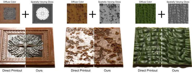
Fig. 1. The input to our system is a diffuse color and spatially-varying gloss. We first reproduce the color using commercial ink-jet printers (left halves). Next, as a post-processing step we use our custom printer to jet varnishes that match the input reflectance (right halves).
3D printing technology is a powerful tool for manufacturing complex shapes with high-quality textures. Gloss, next to color and shape, is one of the most salient visual aspects of an object. Unfortunately, printing a wide range of spatially-varying gloss properties using state-of-the-art 3D printers is challenging as it relies on geometrical modifications to achieve the desired appearance. A common post-processing step is to apply off-the-shelf var-nishes that modify the final gloss. The main difficulty in automating this process lies in the physical properties of the varnishes which owe their ap-pearance to a high concentration of large particles and as such, they cannot be easily deposited with current 3D color printers. As a result, fine-grained control of gloss properties using today’s 3D printing technologies is limited in terms of both spatial resolution and the range of achievable gloss. We address the above limitations and propose new printing hardware based on piezo-actuated needle valves capable of jetting highly viscous varnishes. Based on the new hardware setup, we present the complete pipeline for controlling the gloss of a given 2.5 D object, from printer calibration, through material selection, to the manufacturing of models with spatially-varying
Authors’ addresses: Michal Piovarči, Università della Svizzera italiana, Switzerland; Michael Foshey, Massachusetts Institute of Technology; Vahid Babaei, Max Planck Insti-tute for Informatics, Germany; Szymon Rusinkiewicz, Princeton University; Wojciech Matusik, Massachusetts Institute of Technology; Piotr Didyk, Università della Svizzera italiana, Switzerland.
© 2020 Association for Computing Machinery.
This is the author’s version of the work. It is posted here for your personal use. Not for redistribution. The definitive Version of Record was published in ACM Transactions on Graphics, https://doi.org/10.1145/3414685.3417850.
reflectance. Furthermore, we discuss the potential integration with current 3D printing technology. Apart from being a viable solution for 3D printing, our method offers an additional and essential benefit of separating color and gloss fabrication which makes the process more flexible and enables high-quality color and gloss reproduction.
Additional Key Words and Phrases: appearance reproduction, spatially-varying reflectance manufacturing, gloss printing
ACM Reference Format:
Michal Piovarči, Michael Foshey, Vahid Babaei, Szymon Rusinkiewicz, Wo-jciech Matusik, and Piotr Didyk. 2020. Towards Spatially Varying Gloss Reproduction for 3D Printing. ACM Trans. Graph. 39, 6, Article 1 (Decem-ber 2020), 13 pages. https://doi.org/10.1145/3414685.3417850
1 INTRODUCTION
Reproducing objects’ appearance is essential for their visual appeal. Recent advances in multi-material 3D printing allow us to create intricate geometrical shapes with faithful color [Sumin et al. 2019] and translucency [Urban et al. 2019] reproduction. The method of choice for fabrication is ink-jet 3D printing [Sitthi-Amorn et al. 2015; Stratasys 2016], which allows for deposition of colored materials with high spatial resolution. Going beyond color and translucency, however, another crucial component of an object’s appearance is gloss. When carefully chosen, it can convey objects’ functional
properties, enhance perceived value, or create intricate patterns that can improve the visual appeal of objects.
Despite the significant visual influence and potential of carefully edited gloss, we rarely observe 3D-printed parts with spatially-varying gloss properties. Current state-of-the-art 3D printers, such as [Stratasys 2016], and their software offer minimal choice. Natu-rally, printed objects have a glossy finish. If a matte finish is desired, it is created by covering the object with support material that, upon removal, introduces roughness. Irrespectively of the chosen option, the final finish of the object’s surface further depends on the printed geometry.
One of the main challenges in fabricating spatially-varying gloss properties lies in the printing process itself. This limitation is directly linked to the hardware design. The ink-jet printheads used in 3D printing have tiny nozzles, typically around 20 microns in diameter, to enable high-resolution printing. Consequently, the deposition of highly viscous materials with larger particle size is challenging and hampers the robustness of the printing process. On the other hand, a wide range of reflectance properties is usually achieved by different concentrations of reflective or absorbant particles, which increase the viscosity of the materials significantly [Tipsotnaiyana et al. 2013]. As a result, the same nozzles that are required for achieving high-resolution prints are not suitable for printing a wide range of gloss. Various alternative manufacturing techniques with a wider gamut of printable gloss were proposed [Matusik et al. 2009; Pereira et al. 2017] to alleviate this issue. However, due to the difficulty of integration with the high-resolution color 3D printing process, there is still no well-established workflow for full appearance fabrication. The only available solution currently allowing for modifying gloss using commercial ink-jet printers is to change the surface roughness by introducing a surface geometry [Rouiller et al. 2013; Elkhuizen et al. 2019]. However, the range of gloss that can be produced by these techniques is limited not only by the properties of 3D printable materials but also by the printing resolution.
To address the current limitation in gloss reproduction, we
pro-pose a novel printing system based on PICO Pµlse® 1technology.
The printer is capable of depositing materials with very high viscos-ity and relatively large particle sizes. This gives us the opportunviscos-ity to control the glossiness of a surface by using off-the-shelf varnishes. We develop a pipeline to support the hardware with a full work-flow for manufacturing objects with fine-grained spatially-varying gloss. For optimal printability of varnishes with such a wide range of properties, we develop a calibration procedure that fine-tunes varnish-specific jetting parameters. We use our setup to jet and characterize a large set of varnishes including varnishes based on mineral-spirits, water, and oil. We characterize our varnishes by performing dense measurements of reflectance and fitting them to analytical BRDF models. Based on this characterization, we per-form varnish selection to maximize the gloss gamut. We analyze the quality of the samples and show that mixing varnishes affects not only the reflectance but also the quality of the resulting halftone pattern due to on-surface spatial mixing before fully curing. Conse-quently, we propose a data-driven, simplex-based prediction model 1
https://www.nordson.com/en/divisions/efd/products/jet-dispensers/pico-pulse-valve
for computing the aggregate gloss of a halftoned mixture. Its addi-tional feature is the capability of accounting for the visual quality of the generated halftone pattern. The model allows us to create sur-faces with controllable and spatially-varying gloss properties. We demonstrate the capabilities of the entire pipeline by manufacturing several 2.5 D objects with spatially-varying gloss.
The main contribution of this paper is the complete system for gloss reproduction using varnishes with a wide range of viscosities and particle sizes. We discuss all the building blocks required for such a system and show their practical implementations. Our sys-tem and the produced results demonstrate the feasibility of using varnishes for fine control of gloss properties of objects produced using 3D printing technology.
2 RELATED WORK
Fine control of objects’ appearance is the desired functionality of both display devices [Hullin et al. 2011] and fabrication processes [Hullin et al. 2013]. Recent developments in 3D printing and com-putational fabrication have enabled the fabrication of objects with prescribed color, reflectance, and translucency. Still, many limita-tions persist. In this section, we provide an overview of recent techniques for appearance fabrication with a focus on reflectance and gloss properties.
2.1 Reflectance Fabrication
General techniques tackling the problem of appearance try to repro-duce BRDF of a given surface accurately. One class of methods try to achieve this goal by modifying the microgeometry of the surface. The idea follows the microfacets theory [Cook and Torrance 1982], where a surface is assumed to be a composition of tiny reflecting planes. By controlling their normal distributions, different BRDFs can be achieved. Several techniques realize this idea [Weyrich et al. 2009; Rouiller et al. 2013; Piovarči et al. 2017]. Unfortunately, the most prominent limitation is the scale at which the BRDF properties can be modified and varied. An interesting approach was proposed by Levin et al. [2013]. Using a high-precision fabrication process realizing features at 2 − 3 µm, they demonstrated a reproduction of resolution spatially varying BRDF properties. Despite the high-quality results, the technique requires special fabrication facilities, and therefore, is not suitable for combining with 3D printing.
More similar to our approach is the work of Matusik et al. [2009]. Instead of modifying the local geometry, they proposed to use a broad set of inks that span a wide range of different reflectance prop-erties. Their work presents a complete system for printing digital mixtures of inks to achieve desired, spatially-varying 2D surface appearance. Mixing different inks on top of the object’s surface can be combined with surface geometry optimization [Malzbender et al. 2012; Lan et al. 2013]. At each spatial location, the desired BRDF is approximated with a height-field coated by dithered inks. The coupled optimization enables the generation of anisotropic samples and widens the range of available reflectance properties. The main drawback of these methods comes from the coupling between color and gloss fabrication. The appearance reproduction has to be for-mulated as a joint optimization, which leads to a large set of base inks, and therefore, complicates the hardware design. Additionally,
since materials required for reproducing matte appearance contain larger particles and are more viscous, they cannot be deposited at very high resolutions. While not a severe limitation for gloss re-production, where common objects manifest relatively low spatial variation in gloss properties, the capability of depositing materials at high resolutions is critical for high-quality color reproduction. In contrast, our method decouples the manufacturing of color and gloss by depositing varnishes on top of a colored surface. The color can be produced using a commercial ink-jet printer at a resolution of 600 DPI or higher. We can then modify the gloss at a lower resolution, i.e., 79 DPI using our hardware.
Reflectance variation can be also achieved by modifying the ing parameters of the available materials. In the context of 2D print-ing, plotting with glossy varnishes has been a subject of investi-gation. Such a system was presented by Baar et al. [2014]. They used a 2D plotting system for multi-pass printing. By varying the order of inks, drying time, and varnish coverage, they were able to introduce a roughness to the surface, which resulted in different gloss levels. The idea can be abstracted to stereolitography where the surface roughness can be achieved by using sub-voxel growth of the printing resin [Luongo et al. 2019]. Unfortunately, achiev-ing matte finish usachiev-ing such techniques with a glossy varnish is challenging [Samadzadegan et al. 2015]. Within the same body of work Elkhuizen et al. [2019] proposed to print multiple layers of UV-curable transparent material on top of glossy surface finish. The geometry created during this process introduces roughness to the surface, which results in a more matte appearance. They demon-strate capabilities of achieving reflectance properties ranging from 85 to 4 gloss units when measured with a glossimeter at 60-degrees angle. Although the method pushes the hardware capabilities to its limits, the authors note that for a full gloss reproduction of paintings an even more matte finish is required. Comparing to this work, our technique enables the reproduction of a large range of surface fin-ishes with continuous variation from highly matte (0.9 gloss units at 60-degrees) to highly glossy (87 gloss units at 60-degrees) by depositing only a single uniform layer of material. We achieve this by proposing a system that is capable of precise deposition of matte varnishes.
2.2 Color Reproduction
Color is the primary appearance property of an object. The state-of-the-art color 3D printing solutions rely on UV curable ink-jet printers [Sitthi-Amorn et al. 2015]. Similar to 2D printers, they also mix several base materials, usually CMYKW, to achieve full-color. There is, however, a much broader choice in terms of materials and mixing strategies. The most common techniques perform halftoning of semi-opaque printing materials [Brunton et al. 2015]. Due to significant scattering properties, special strategies were proposed to compensate for the effect [Elek et al. 2017; Sumin et al. 2019]. Color printing is also possible using only transparent materials that are stacked to produce the desired color [Babaei et al. 2017]. Recently, such a technique was also proposed for spectral color reproduction [Shi et al. 2019]. Besides ink-jet printers, color can be produced using different technologies such as paper lamination, powder-binder, or fused filament fabrication, but the quality does not match that of
ink-jet printing. Color of an object can be also modified in a post-processing step where the ink is transfered onto the object surface through a thin water soluble film [Panozzo et al. 2015; Zhang et al. 2015] or a thermoformed plastic sheet [Schüller et al. 2016].
2.3 Translucency Reproduction
Apart from color and reflectance properties, translucency is another factor influencing the appearance of objects. Early works try to optimize the material distributions withing the printing volume to match the subsurface scattering properties [Hašan et al. 2010; Dong et al. 2010]. For homogeneous silicon objects, Papas et al. [2013] determine a mixture of pigments for a given color and translucency reproduction. Most recent work extends a color printing pipeline to translucency by incorporating transparent material [Brunton et al. 2018]. By reinterpreting the alpha channel from additive blending to subtractive mixing the translucency of the material can be encoded in conventional RGBA textures [Urban et al. 2019]. Our work does not address color or translucency printing but assumes that the substrate of the objects contains color information produced by one of the existing techniques. We solely focus on adding a layer of a material to alter the gloss of the object.
3 HARDWARE APPARATUS
To modify the reflectance properties of the surface we seek to deposit varnishes with high spatial accuracy. Conventional inkjet printers are not capable of jetting varnish materials due to their high vis-cosity and large particle sizes. In order to print such challenging materials, we designed a hardware setup based on piezo-actuated needle valves, (Figure 2 top). The jetting head consists of a pres-surized varnish reservoir, the valve body, a piezo actuator, a nozzle of variable diameter (50-300 microns), and a spring-loaded needle valve (Figure 2 bottom left).
One activation cycle of the printing head is depicted in Figure 2 bottom right. To dispense the varnish, the needle valve is opened by the piezoelectric actuator. The valve remains open for a set duration, during which the varnish can freely flow from the nozzle. Afterward, the valve quickly closes. The back pressure on the printing material and force of the closing needle sever a portion of printing material from the print head and project it onto the printing surface. The shape and size of the formed droplets depend on the material proper-ties of the printing material and the amount of energy transferred to the droplet during the jetting process. The energy transferred to the droplet is a non-linear combination of the pressure in the varnish chamber, the time to open and close the valve, and the stroke power of shutting down the needle valve. This relatively simple jetting process coupled with a larger nozzle diameter offers a powerful combination capable of processing a much wider variety of materi-als than inkjet-based printers at the cost of producing larger droplet size.
Our apparatus combines three jet-valve dispensers (PICO Pµlse®
from Nordson EFD, Providence, RI, USA) with a Cartesian robot (Hiwin Mikrosystems, Taichung, Taiwan), a gantry, and a controller. The Cartesian robot is used to move and locate the dispensers in Z and the sample in X and Y . The dispensers are used to deposit
different varnishes. The movement of the Cartesian robot and the timing of the dispensers is coordinated by the controller.
Pressure Piez oac tua tor M ov emen t Open Valve Nozzle Valve Stroke Opening Duration Jet-Valve Body Varnish Reservoir Spring Needle Valve Close Duration t Close Valve
Fig. 2. Varnish printing apparatus (right) consists of needle jetting valves (left). To jet with the valve, the needle rises allow pressurized material to flow. By quickly shutting the valve the material is jetted onto the substrate.
4 VARNISH JETTING
In our experiments, we use of-the-shelf varnishes available in art stores. The varnishes are based on various solvents (water, mineral spirits, oil) and contain various amounts and sizes of particles to produce gloss, matte, or satin finish. The different mechanical and chemical composition of each varnish affect the behavior of droplets during jetting. At the resolution of our jetting processes, even small changes between material batches lead to a decrease in printing quality. As a result, the parameters have to be fine-tuned for each varnish at printing time to achieve consistent droplet quality. In this section, we describe the effect of printing parameters on the resulting droplet shape. Based on this, we propose a varnish cali-bration scheme. Next, we investigate the effect of droplet spacing on the uniformity of the surface coverage. Finally, we present a set of varnishes that can be consistently applied using our hardware setup.
4.1 Effects of Printing Parameters on Droplet Shape
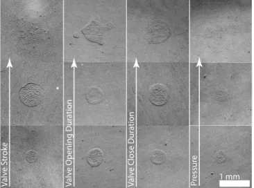
The printing parameters have a direct but non-linear influence on the shape of the printed droplet. To better understand this relation-ship we performed an experiment. We manually optimized parame-ters for a varnish to be able to jet the material. Next, we modified different parameters in isolation to investigate their effect on droplet shape. To compare the shape and geometry of the droplets we use Gelsight scans [Yuan et al. 2017] (Figure 3).
By visual analysis of the results, we can observe that the valve stroke has the highest impact on energy introduced into the droplet. Excessively high pressure results in a forceful surface impact, causes the droplet to splash into the surrounding area. The valve open and close time affect how much of the varnish is allowed to escape the valve and accumulate at the nozzle. The accumulation has a direct influence on the dot size. Pushing the intervals too far results in the spreading of the varnish on the printing nozzle due to surface tension; this results in non-circular droplets. The pressure affects both the amount of varnish that escapes the nozzle during the opening and how much force is introduced into the droplet. This results in a combined effect, of changing both droplet size and shape.
Valv e S tr oke Valv e Opening D ur ation Valv e Close D ur ation Pr essur e 1 mm Fig. 3. Gelsight captures of droplets created by varying the jetting parame-ters: valve stroke, valve open duration, valve close duration, and air pressure.
To achieve consistent droplets, we perform a parameter sweep before printing to calibrate each of our varnishes. Each varnish is prepared based on manufacturers data-sheets. In particular, we mix the golden varnishes in a volume ratio of 1 : 1 with their corresponding solvents. We start from a known working state which allows us to jet the material through the nozzle. Next, we perform a parameter sweep on each of our printing parameters: time the valve is opened, the time it takes the valve to close, how much the valve opens, and the air pressure of the varnish. Using this procedure, we calibrated a set of varnishes. We present the results of the calibration in Figure 4. The varnishes’ droplets are captured using both Gelsight (top) and an optical microscope (bottom). The optical microscope was set up with a blue LED to increase the visual
contrast. Overall shape of our droplets can be well approximated with circular patterns. Most of our varnishes could print reliably at 450-micron resolution. The exceptions are Golden matte heavy gel, Golden gloss extender mixture; where due to the extreme viscosity the printing resolution dropped to >1000 microns.
1 mm
Fig. 4. Gelsight (top) and optical (bottom) scans of varnish droplets for a selection of off-the-shelf varnishes. From left to right, 1:1 ratio of Golden MSA gloss varnish and Golden MSA solvent, 1:1 ratio of Golden MSA satin varnish and Golden MSA solvent, 1:1 ratio of Golden MSA matte varnish and Golden MSA solvent, Schmincke 611 matte varnish, Schmincke 610 gloss varnish, Amsterdam 115 Matte Varnish, 1:1 ratio of Golden matte heavy gel and Golden gloss extender.
4.2 Effect of Varnish Spacing
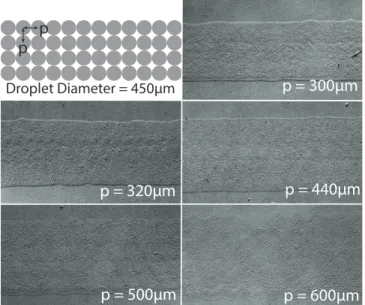
The reflectance of an object depends not only on the material but also on the microstructure of the geometry. In our printing apparatus, the microgeometry is affected not only by the jetting parameters but also by the spacing between printed varnish droplets. In our setting, we do not wish to affect the glossiness through geometry variation. We rather rely on our varnishes which have reported
specular gloss2ranging from very matte (0.9 gloss units measured
at 60-degrees) to high gloss (87 gloss units measured at 60-degrees). To investigate the effect of droplet spacing, we conduct the fol-lowing experiment. We deposit matte varnish with optimized pa-rameters using progressively smaller spacing between the dots and observe the resulting surface roughness (Figure 5). We can note that in the selected range the surface roughness does not deviate significantly due to spacing. On the other hand, the thickness of the applied film is correlated with the change in spacing. We attribute this behavior to the relatively long time (∼30 minutes) it takes for our varnishes to cure after printing. Varnishes in the liquid state are still allowed to flow and form a uniform film on the surface. In order to maintain a uniform coverage, we opted for the spacing of 320 microns which corresponds to tiling the inscribed squares of our varnishes.
4.3 Optimized Jetable Varnishes
Using our hardware apparatus we optimized a set of printable var-nishes capable of consistently jetting at 450-micron resolution (Fig-ure 6). The varnishes were applied on a transparency sheet. The translucency and high degree of smoothness of the transparency sheet guarantee that it does not have an effect on the varnish ap-pearance. With our system, we can successfully jet varnishes with a wide range of viscosities, and more interestingly, handle matte varnishes with particles. This capability allows us to achieve broad coverage of reflectance from very glossy to matte.
2https://www.goldenpaints.com/technicalinfo/technicalinfo_polvar
p
p
p = 300µm
p = 320µm
p = 440µm
p = 500µm
p = 600µm
Droplet Diameter = 450µm
Fig. 5. Effect of varying spacing. In the observed range increasing the spac-ing leads to thinnspac-ing of the film created by the deposited varnish.
Golden Matte Golden Satin Golden Gloss Schmincke Matte Schmincke Gloss
Fig. 6. Photos of our printed varnishes on a cylindrical setup with a line light source.
5 VARNISH SELECTION
The set of varnishes printable on our hardware covers a large range of visual gloss. To quantify the exact reflectance properties we mea-sure the varnishes on a custom-built setup. Next, we approximate the BRDF of varnishes with a low-parameter analytical model, which allows us to represent them in a low-dimensional space. We use this space to visualize the gamut covered by our varnishes and perform varnish selection. 5.1 Measurement Setup Normal View Light Surface θ θ V L Off-the shelf varnishes are designed to
provide optimal surface properties from all viewing directions. Our setup does not introduce significant anisotropy thanks to the spatial mixing that occurs at the boundary of deposited varnishes. Consequently, we assume that our var-nishes have isotropic reflectance
prop-erties. Such an assumption significantly simplifies the hardware required to capture the reflectance since the four-dimensional space reduces to three dimensions. We base our setup on a design pro-posed by Ngan et al. [2005]. Our setup (Figure 7) consists of a black cylinder to which the measurement sample is attached and a series of light sources located at 15, 30, 46, and 60 degrees. We use a matte
black cylinder to eliminate the influence of the measuring setup on the recovered reflectance. Under the assumption of isotropic uni-form reflectance we can capture a representative dense reflectance measurement from a single shot of each light source (Figure 7 right). The reflectance is plotted as a function of the signed difference be-tween the angle of the view direction with the surface normal and
the angle of light direction with the surface normal:∆θ = θV− θL.
Measurement Sample
Camera Point Lights Control Box
Fig. 7. Our measurement setup and sample capture of matte and satin varnish.
5.2 BRDF Model Fitting
To perform a selection of our varnishes we seek a low-dimensional embedding in which we can compare the reflectance. Good candi-dates for such embedding are analytical reflectance models. We con-sider fitting multiple models into our data: Ward isotropic model [Ward 1992], Cook-Torrance model [Cook and Torrance 1982] with Back-mann distribution [Cook and Torrance 1982], and Cook-Torrance model with GGX distribution [Trowbridge and Reitz 1975; Walter et al. 2007] and their multi-lobe variants [Lafortune et al. 1997]. We fit the model to our data by minimizing:
min
m,F0
|D − M(d, m, F0)|, (1)
where M is the analytical model; the analytical model has input
roughness m ∈ Rl, and Fresnel factor F0∈ Rl (or intensity in case
of Ward model); l is the number of lobes that we are fitting, d is the diffuse component estimated as the 5th percentile of intensi-ties captured in our measurement, and D are our measured values. We minimize Equation 1 using L-BFGS optimization [Nocedal and Wright 2006]. Our fitting attempts to approximate the data as closely as possible and does not impose constraints on physically correct reflectance.
An interesting feature of our fitting is that, unlike previous work [Ngan et al. 2005], it does not need additional weights to properly approximate the measured lobe. This is thanks to our hardware setup. By measuring samples on a cylinder we achieve denser sam-pling in the regions of mirror reflection and, therefore, additional reweighting is unnecessary.
We analyzed the data by comparing fitting errors and found that the Cook-Torrance model with GGX distribution best approximates our measurements. We also verified that a single-lobe model is sufficient to capture the appearance of our samples and a multi-lobe model does not significantly improve our results. Figure 8 shows the final fits to three of our varnishes and their corresponding renderings using the Mitsuba renderer [Jakob 2010].
0 0.1 0.2 -0.1
-0.2 -0.2 -0.1 0 0.1 0.2 -0.2 -0.1 0 0.1 0.2
Luminance
Delta Theta Delta Theta Delta Theta
0 20 40 60 80 100 120 140 160 0 0.1 0.2 0.3 0.4 0.5 0.6 0.7 0.8 0.91 0 0.02 0.04 0.06 0.08 0.10 0.12 0.14 0.16
Golden Gloss Golden Satin Golden Matte
Rendering
Measurement Fitted Model
Fig. 8. Fitted raw measurements of our varnishes (top) and corresponding rendering with the fitted model parameters (bottom).
5.3 Reflectance Gamut
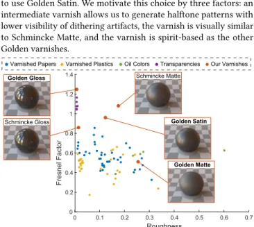
Fitting a Cook-Torrance model allows us to plot our varnishes in a two-dimensional space formed by roughness and Fresnel factor. Due to the non-physical nature of our fitting process roughness and Fresnel factor are not orthogonal parameters in the analytical model. Therefore, we cannot simply quantify our gamut by a convex hull of our varnishes in the parameter space. Instead, we visually inspect the varnishes and select those that maximize the perceived gloss.
Our hardware apparatus can print simultaneously with three varnishes. We wish to select these varnishes such that they span the largest possible gamut of reflectance. We opt for Golden Matte and Golden Gloss varnishes as they represent our most diffuse and most specular sample respectively. For the last varnish, we decided to use Golden Satin. We motivate this choice by three factors: an intermediate varnish allows us to generate halftone patterns with lower visibility of dithering artifacts, the varnish is visually similar to Schmincke Matte, and the varnish is spirit-based as the other Golden varnishes. 0 0.1 0.2 0.3 0.4 0.5 0.6 0.7 Roughness 0 0.2 0.4 0.6 0.8 1 1.2 1.4 Fresnel Factor
Varnished Papers Varnished Plastics Oil Colors Transparencies Our Varnishes
Golden Gloss
Golden Satin
Golden Matte Schmincke Gloss
Schmincke Matte
Fig. 9. The reflectance gamut achievable by our varnishes (orange). The gamut contains various hand-made samples for comparison: varnished pa-per (blue), varnished plastics (yellow), oil colors (green), and transparencies (purple). The varnishes we selected for printing are in bold.
To estimate the gamut of achievable gloss we assume a single lobe model as it holds well for the base varnishes. However, during halftoning the surface is covered with up to three varnish primaries. These varnishes form individual droplets that manifest in the mea-surements as a mixture of three separate lobes. As a result, the phenomenological model is only a rough predictor of the gloss achievable by our setup and we rely on raw measurements for re-flectance predictions.
6 GLOSS REPRODUCTION
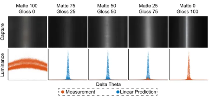
To reproduce the desired reflectance with a limited set of primary varnishes we can use a halftoning algorithm. For each spatial loca-tion, the algorithm selects the primary closest to the target. This produces an error which is compensated for by propagating to neighboring locations. The algorithm operates under the assump-tion that the deposited materials combine linearly. However, since our varnishes are not cured at deposition time they can mix in a liquid state and manifest non-linear mixing behavior. Therefore, we need to verify the linearity assumption of varnish halftones. We prepared three halftoning patterns linearly interpolating from matte to gloss in uniform steps, and printed them on our setup (Figure 10 top). We measured the applied varnishes and compare the physical measurement with prediction based on linear mixing (Figure 10 bottom).
Luminance
Delta Theta
Measurement Linear Prediction
Capture
Matte 100
Gloss 0 Matte 75Gloss 25 Gloss 50Matte 50 Gloss 75Matte 25 Gloss 100Matte 0
Fig. 10. Test of linearity of varnish halftoning. We start by generating halftone patterns and applying them on a substrate. The samples are then measured and compared with linear prediction.
We can observe that the patterns of halftoned gloss are mixing during printing. As a result, the 50/50 pattern looks almost as a single material. This mixing affects the visual properties and violates the linearity assumption which means we cannot rely on the linear mixing to produce correct results.
6.1 Simplex-Interpolation for Halftone Reflectance Prediction
When observing the interpolated samples we can see that while the linearity assumption does not hold the change in varnish properties smoothly varies from matte to glossy. We leverage this observation to formulate a simplex-interpolation model for the prediction of the reflectance of halftone samples. Due to varnish dithering the final appearance can be a combination of multiple phenomenological effects. To not impose any assumption on the predicted data we directly use the measurements. The input to the model is a mixing
ratio and a data set of previously observed mixing ratios with as-sociated measurements. The output is a prediction of reflectance measurement.
A halftone screen can be treated as a spatial approximation of a given mixture of varnish primaries P. The mixture is parameterized
by the mixing coefficients αiwhere i ∈ P andÍ
iαi= 1. Using this
definition a set of N varnishes defines a standard N −1 simplex. With a linear halftoning model we could predict the reflectance of various mixtures by using the barycentric coordinates of varnishes in our base set P. However, due to nonlinear mixing such interpolation would not hold. To address this issue we propose a more intensive data-driven model. We manufacture and print a set of interpolated varnishes to better approximate the non-linear mixing (Figure 11 left). We used the following mixing ratios: 75/25/0, 50/50/0, 50/25/25, 33/33/33 and their permutations. Due to the non-linear mixing of multiple varnishes, we can not rely on reflectance models. Instead, we represent the reflectance as quantized raw measurements. We parameterize the measurements in the angular domain as the
dif-ference between the view and light direction. The difdif-ference∆θ is
then quantized with a resolution of 0.1-degree change. To predict new samples we perform a hyper-tessellation of the measured data points (Figure 11 left). Then to predict a new unobserved mixture we first find its enclosing sub-simplex and then use the barycen-tric coordinates within the sub-simplex (Figure 11 left) to predict a reflectance measurement (Figure 11 right).
Gloss Matte Satin *
λ1
+λ2
+λ3
* λ1 λ2 λ3Fig. 11. A two-dimensional simplex created to predict the reflectance of gloss halftones. To predict a new sample we locate the enclosing simplex and use barycentric coordinates to interpolated our measurements.
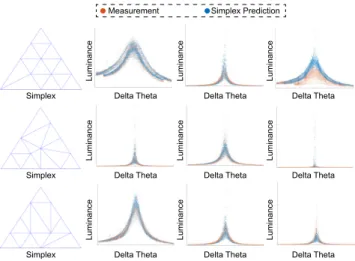
We evaluate our model using a cross-validation scheme. We re-peatedly leave out three varnishes and rebuild our model (Figure 12 left). Next, we predict the reflectance of the missing varnishes (Fig-ure 12 right). We can observe the model has an overall good perfor-mance. The largest discrepancy from the prediction occurs when dealing with a glossy material. This is likely due to the highest non-linearity of our function when mixing the glossy varnish since a small amount of different varnish already produces an observable difference in gloss.
6.2 Predicting Halftone Pattern Quality
Due to the large size of our varnish dots, the halftoning pattern can be observed by naked eye from a sufficiently close distance. How-ever, the physical mixing of varnishes masks the halftone pattern and improves the quality of the observed gloss. To take advantage of this property and incorporate it into our halftoning algorithm we propose a heuristic model based on observation of the varnish behavior.
Simplex Delta Theta Delta Theta Delta Theta
Luminance
Luminance
Luminance
Measurement Simplex Prediction
Simplex Delta Theta Delta Theta Delta Theta
Luminance
Luminance
Luminance
Simplex Delta Theta Delta Theta Delta Theta
Luminance
Luminance
Luminance
Fig. 12. Cross-validation of our simplex-based reflectance prediction. Leav-ing out multiple samples, creatLeav-ing a new tesselation, and predictLeav-ing the missing samples.
The input to our heuristic model is a desired mixing ratio. The output is a single number representing the quality of the halftone pattern where a lower number represents a surface with higher quality. To define the heuristic we observed the spatial mixing of our varnishes. The spatial mixing causes a smooth material transition between two varnish droplets. Additionally, a droplet always mixes only in its one-ring neighborhood. To model the spatial blurring of our varnishes we use Gaussian filters with a standard deviation of 0.5 and kernel support of 3 × 3 which represents the droplets smoothly mixing with the surrounding droplets. The blurring is applied onto halftone screens corresponding to 4×8 cm patches used for our measurements. This is equivalent to 158×316 droplets. Next, we compute the standard deviation of the pattern. The standard deviation estimates the visibility of the blurred halftone pattern. The visibility predictor σ can be evaluated as:
σ (α )= N Õ i r 1 M − 1 Õ (G ∗ P (αi) − αi)2, (2)
where M is the number of droplets in the dithering pattern, G is a Gaussian kernel with 3 × 3 support and standard deviation of 0.5, and P is a function that generates halftone pattern for mixture α . We can see the results of predicted and observed dithering artifacts in Figure 13.
0 0.333 0.4851 0.6592 0.7696 100-0-0 50-50-0 75-25-0 33-33-33 50-25-25
Quality
Fig. 13. Predicting dithering pattern visibility for different varnish mixtures of matte-glossy-satin.
6.3 Prescribed Reflectance Reproduction
We use our simplex model to reproduce prescribed reflectance. The input to our method is a per-pixel assignment of the desired re-flectance. The output is per-pixel mixing ratios of our base var-nishes that best match the input. At each spatial location, we solve a minimization problem searching for the optimal mixing ratio that reproduces the desired reflectance. Since our varnish combina-tions can result in similar reflectance we encourage halftone pattern uniformity by adding pattern quality as a regularizer. The final minimization problem is then:
minα Õ(RT − S(α ))2+ σ(α), (3)
where α = α1, α2, ...αN is the set of the mixing ratio of our base
varnishes, RT is target reflectance, S is our simplex predictor which
transforms mixing ratios into reflectance measurements and σ (α ) is the predictor of dithering pattern visibility for mixture α computed using Equation 2. We minimize Equation 3 with a L-BFGS method [Nocedal and Wright 2006]. After the mixing ratios are generated we use vector error diffusion with Stucki weights to dither the desired mixing ratios into our varnish primaries [Stucki 1982; Lau and Arce 2007].
The regularization term is ensuring to prefer patterns with less visible halftone screens. As an indirect consequence, this leads to a preference for mixing more similar varnishes as lower mixing ratios and mixing ratios close to 50:50 create more uniform patterns. We can observe the effect in Figure 14. The roughness map directly corresponds to the Cook-Torrance model. Lower values represent glossier materials and higher values matte materials (Figure 14 left). Our dithering pattern (Figure 14 middle) is encoded into RGB such that R corresponds to matte material, G corresponds to gloss and B corresponds to satin. For comparison we also show the dithering pattern without our visibility predictor (Figure 14 right). We can ob-serve that the visibility predictor successfully reduces the dithering noise by removing isolated varnish droplets.
Satin Varnish
Input Roughness Our Quality Optimization Without Regularization Matte Varnish Glossy Varnish
Fig. 14. Prescribed roughness for a target reflectance (left) is dithered using our simplex model with (middle) and without (right) dithering pattern visibility optimization.
7 RESULTS
We demonstrate the capabilities of our system by creating several samples with spatially-varying gloss. We fabricate flat samples of varnishes applied on transparency sheets that showcase the fine-grained spatially-varying gloss achievable using our hardware. Ad-ditionally, we chose three height-fields with associated spatially-varying BRDF that we reproduce using our system. We compare the final manufactured pieces against direct printouts from a com-mercial printer.
7.1 Flat Samples
We visualize the range of achievable reflectance by manufacturing a gradation of gloss ranging from highly matte to highly glossy in Figure 15. The transition is composed of uniform patches of gloss manufactured by dithering a predefined mixture of our base varnishes. To capture the samples, we place them perpendicularly to a display showing a checkerboard with a grid size of approximately 3 millimeters. We position the camera in the middle of each sample at a 30-degree angle to capture the reflection of the checkerboard pattern. The resulting transition demonstrates the range of gloss we can achieve with our system.
100% 0% 0% Matte Satin Gloss 75% 0% 25% Matte Satin Gloss 50% 0% 50% Matte Satin Gloss 0% 50% 50% Matte Satin Gloss 0% 25% 75% Matte Satin Gloss 0% 0% 100% Matte Satin Gloss 33% 33% 33% Matte Satin Gloss Camera Display Sample 30°
Fig. 15. A gradation of gloss formed by jetting uniform patches of various varnish mixtures. The images are captured by placing the samples against a display showing a checkerboard pattern.
To validate the capabilities of our setup in creating fine-grained spatially-varying gloss, we prepare two samples: Waterfall, and Knight (Figure 16). The input gloss on Waterfall is created by treat-ing its luminance image as a gloss map. For Knight, we edited the gloss manually. Both gloss maps are halftoned using vector error diffusion to generate the input to our printer. To capture the man-ufactured pieces we illuminate them from a 60-degree angle with an area light source and capture the photos with a camera at the specular direction (Figure 16 left). To predict the final appearance, we reconstruct the setup in the Mitsuba renderer. For reflectance parameters of the halftoned varnishes we use the fitted BRDFs ex-plained in Section 5.2. Similarly to our dithering pattern visibility predictor we simulate the spatial mixing of our varnishes by blurring the halftoned maps with a Gaussian filter of 3×3 with a standard deviation of 0.5. We can observe that this simple phenomenological model is effective at predicting the appearance of our manufactured pieces (Figure 16). The main discrepancy in the photos comes from imprecisions in the light setup used to capture the physical samples. More precisely, the lamp used for capture is not a perfect spotlight which is used for the rendering. In particular, the real lamp provides a bright spotlight with a gradual falloff towards the boundaries.
Finally, we highlight the capability of our setup to separately manufacture color and gloss. To this end, we printed two colored photos of Knight and Waterfall on a commercial inkjet printer. To demonstrate the separability we modify the reflectance by placing
Gloss Map Dithering Rendering Photo Capture
60° 60°
Fig. 16. Spatially-varying gloss is defined with two varnishes: matte (black) and glossy (white); and dithered using our device. To validate the fabrication we capture the fabricated samples with an area light source and compare with rendered predictions.
transparency sheets with spatially-varying gloss created using our setup on top of the printed photos. We capture the samples with a camera at an elevation of 40-degrees and with a light source moving azimuthally from 0 to 180 with a 40-degree elevation, as shown in Figure 18. We can observe that the final fabricated samples manifest spatially-varying gloss and high-resolution color.
7.2 Height-field Samples
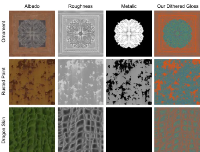
To demonstrate potential integration with current 3D printers, we use our system to apply gloss on previously-3D-printed 2.5D sam-ples. To this end, we prepare three height-fields: a door ornament, a rusted paint, and a polished leather patch. The models have associ-ated albedo, roughness, and metallic maps that encode parameters of a Cook-Torrance model with GGX distribution. The roughness map modifies the microfacet distribution, and the metallic map de-termines the Fresnel term. We use these maps to obtain parameters of spatially-varying BRDF, which is later inputted to our model for generating a halftoning pattern. The inputs and the corresponding halftoning patterns are presented in Figure 17.
Metalic Roughness Albedo Rusted Paint Ornament Dragon Skin
Our Dithered Gloss
Fig. 17. Albedo, roughness, and metallic textures for our objects with their corresponding generated halftone patterns.
Color Gloss Color + Gloss Color Gloss Color + Gloss -1 EV -1 EV -1 EV -1 EV -1 EV -1 EV -1 EV -1 EV -1 EV -1 EV -1 EV -1 EV -1 EV -1 EV -1 EV -1 EV -1 EV -1 EV 40° 40° 40° 40° 40° 40° 0 EV 0 EV 0 EV 0 EV 0 EV 0 EV 0 EV 0 EV 0 EV 0 EV 0 EV 0 EV 0 EV 0 EV 0 EV 0 EV 0 EV 0 EV
Fig. 18. Appearance manufacturing with separate fabrication of color (ink-jet printer) and gloss (our device). The final combined appearance manifests both high-resolution color and spatially-varying gloss. Photos are captured at two exposure values (+0, -1) with a still camera and a moving light source. For a full visualization please see the supplementary video.
We print the colored models using Stratasys ObjetJ750 with a matte finish (Figure 19, top rows). Then, we use our device to modify the gloss of the printouts (Figure 19, bottom rows). We align the printed samples with the jetting head by placing them into the cor-ner of the print bed which is calibrated with respect to the nozzles. To capture the samples, we placed a camera at an elevation of 40-degrees and rotated the light source around the sample at a constant elevation angle (Figure 19 top). Figure 19 shows captures from three light source positions at azimuth directions of 0, 45, and 90 degrees. To visualize the spatially-varying gloss, we select two regions and plot the 95th percentile of luminance captured by the camera (Fig-ure 19 right). It can be observed that even though the initial samples were printed in the printer’s matte mode, they exhibit significant specularity seen as peaks in the plots. The luminance profiles for our samples significantly differ. More importantly, in contrast to direct printouts, our system produces samples with a measurable variation between different locations on the samples. Even though the perceived effect is affected by the underlying geometry [Ho et al. 2008], we can observe visible variation in spatially-varying gloss properties. Another interesting outcome is that thanks to our capa-bility of depositing highly viscous matte varnishes, we can achieve significantly more matte finish than the one available on the color printer. This is visualized by almost flat profiles for some locations on our samples. Luminance Phi Luminance Phi Luminance Phi Dir ec t P rin t O urs O urs O urs Luminance Phi Luminance Phi Luminance Phi Dir ec t P rin t Dir ec t P rin t ϕ 40° 40° 40° 40° 40° 40° ϕ ϕ
Fig. 19. Manufactured height-fields without varnish (top) and with halftoned varnish using our system (bottom). Photos are captured with a still camera and moving light source. We plot the luminance of two loca-tions as the light rotates around to showcase the gloss variation achieved by our system. For the full capture please see the supplementary video.
8 LIMITATIONS AND FUTURE WORK
While this paper presents a complete system for applying varnishes on 3D printed objects, there are several areas which should be further investigated before the capabilities of such a system are fully exploited.
In our experiments, we use varnishes with isotropic reflectance. A potential direction of future work is to enhance the varnishes with particles that can produce the anisotropic appearance, though this would also require a method for aligning these particles [Pereira et al. 2017]. Such alteration opens up questions on how to efficiently capture, model, and predict the appearance of anisotropic varnishes. Another limitation of off-the-shelf varnishes is that while they strive to be color neutral, often yellowing or bluing of the underlying substrate can happen. To this end, an interesting direction of future work is to estimate how the varnishes affect the spectral colors and compensate for any undesired color shifts. Additionally, our system assumes that the varnishes are deposited on top of a colored substrate. As a result, the highlights created by our printer are always white. A potential avenue for future work is to investigate how to alter the color of the glossy highlight.
Our varnishes were measured on transparency sheets. While this procedure is useful for characterizing varnish properties, the final reflectance of the surface is a combination of the varnish and the underlying structure, in particular, microgeometry [de la Rie et al. 2010]. Any imperfections in the surface finish have an effect on the final appearance. It is possible to minimize such effects by using a self-correcting hardware setup [Sitthi-Amorn et al. 2015]. However, a more viable solution is to include the hardware impre-cision into the gloss modeling and halftoning algorithm to enable high-precision gloss editing on current hardware solutions.
As we demonstrated in Figure 20, when applying our varnishes on tilted surfaces, they stick to the substrate. Unfortunately, we observed that the appearance of the surface changes slowly as the slope increases. We attribute this effect to the staircase artifacts introduced by the 3D printer as well as a different mixing behavior of varnishes on inclined surfaces. While the former can be overcome by sandpapering the surface [Elek et al. 2017; Sumin et al. 2019], handling both requires extending our model such that it compensate for the influence of the slant on the final appearance. This leads to an interesting observation that, in order to print a complex 3D object with uniform gloss, the system should vary the varnish mixtures according to the underlying geometry.
0° 5° 10° 15° 20° 25° 35° 40° 45° 50° 55°
α = α β β
Fig. 20. Differently slanted 3D printed surfaces covered with the same coverage of Golden gloss varnish, captured at specular configuration. The angles below the pictures indicate the deviation of the surface from the 3D printer’s tray. The appearance start to show significant deviations from the flat surface at approximately 20◦.
The proposed printing hardware enables separation between color and gloss manufacturing. This is advantageous from the fabri-cation point of view as fewer materials are necessary to achieve faith-ful reproductions. However, the joint color and gloss appearance management remains a coupled and challenging problem [Wills et al. 2009]. In this context, an interesting question is how to leverage gloss metamerism i.e., perceiving lobes of different shapes as being equivalent, for appearance reproduction. Here, the main challenge is that gloss lobes with a similar width and height can be difficult to distinguish at a quick glance, but it is possible to see the difference under carefully controlled conditions. Hence, true metamerism of gloss is a function of how carefully one looks. Quantifying this has been attempted by works developing a BRDF similarity metric [Fores et al. 2012; Pereira and Rusinkiewicz 2012; Sun et al. 2017], but to our knowledge, no standardized solution exists yet. As a result, future work for understanding the physical and perceptual coupling between color and gloss is critical in achieving high-quality reproductions.
Our model for predicting the appearance of different mixtures of varnishes inherits the general limitations of data-driven approaches. While we demonstrate that a relatively sparse sampling of different mixing ratios leads to a good prediction, due to the non-linearity of the modeled function, better prediction can be achieved by careful selection of the sampling nodes [Warburton 2006]. Besides improv-ing the model accuracy, the samplimprov-ing strategy can also accelerate the interpolation with larger number of primary varnishes [Babaei and Hersch 2016].
The dithering pattern visibility predictor assigns a general score to a pattern irrespective of the appearance of its materials. The relatively simple predictor helps improving the pattern quality by removing isolated droplets and regularizing the dithered patterns. An interesting direction of future work is incorporating the re-flectance of the dithered varnishes into the prediction. This way the generated halftones could prefer more similarly looking materials that can lead to smoother transitions.
Since our varnish deposition system uses only a single nozzle it is slower than commercial inkjet printers at depositing a single layer of material. More specifically, covering a 100 × 50 millimeters rectangle takes approximately 30 minutes on our setup. This process can be significantly optimized by enhancing the hardware setup. However, printing a medium-sized object on a 3D printer requires thousands of layers. In contrast, our prototype varnish application is only a single layer and as such it does not introduce a significant bottleneck into the manufacturing process.
Finally, a single deposition pass of varnishes can handle only 3D objects that are height-fields. Therefore, modifying the gloss of an arbitrary 3D printed object requires multiple passes during which the object is placed at a different orientation. The process requires an accurate alignment [Sitthi-Amorn et al. 2015], or ideally, an automated system. Alternatively, the object can be printed in multiple parts, each of them being a height-field [Herholz et al. 2015]. While this may be considered a significant limitation, in fact, there is no other viable solution to this problem. Current color 3D printing devices generate appearance, which differs depending on the supporting material placement and the local slope of the surface. With printers such as ObjetJ750 [Stratasys 2016], it is not possible to
affect the appearance at the bottom of the object which is attached to the print bed. Considering these limitations, we believe that our deposition system is a viable solution for physical gloss modification with a clear, albeit challenging, path for fabrication of arbitrary 3D printed objects.
9 CONCLUSION
Despite steady progress in 3D printing technology, full appearance reproduction is still a challenging task due to the difficulties in de-positing a wide range of materials, lack of established appearance fabrication processes, and limitations on surface finish imposed by hardware designs. In this work, we took a step towards addressing these limitations, enabling further development of appearance fab-rication using 3D printing technology. To this end, we presented a novel hardware apparatus capable of jetting highly viscous materi-als, which enables reliable deposition of a wide range of varnishes. We demonstrated the required steps for building a system for achiev-ing high-quality, spatially-varyachiev-ing gloss of 3D printed samples. We presented a method for selecting printing materials and calibrating their deposition. To address complex spatial on-surface material mixing, we proposed a data-driven model for predicting the ap-pearance. Furthermore, we take into account the influence of the halftoning pattern to improve the achieved finish quality. Finally, we demonstrated the system’s performance and expressiveness by manufacturing several examples with spatially-varying gloss. While each of these steps can be further improved, we believe that the pre-sented workflow serves as a complete set of basic building blocks of a varnish-based appearance fabrication process that can guide future improvements and integration with existing 3D printing systems.
ACKNOWLEDGMENTS
We would like to thank Sebastian Cucerca for his help with mea-suring the varnish samples, Gretchen M Eggers for her help with calibrating the jetting nozzles, and Bernd Bickel for his prompt help with printing the colored heightfields. This work is graciously supported by the following grant agencies: ERC Starting Grant (PERDY-804226), NSF (grants CHS-1617236, 1815070, and IIS-1815585).
REFERENCES
Teun Baar, Sepideh Samadzadegan, Hans Brettel, Philipp Urban, and Maria V Ortiz Segovia. 2014. Printing gloss effects in a 2.5 D system. In Measuring, Modeling, and Reproducing Material Appearance, Vol. 9018. International Society for Optics and Photonics, 90180M.
Vahid Babaei and Roger D Hersch. 2016.N -Ink Printer Characterization With Barycen-tric Subdivision. IEEE Transactions on Image Processing 25, 7 (2016), 3023–3031. Vahid Babaei, Kiril Vidimče, Michael Foshey, Alexandre Kaspar, Piotr Didyk, and
Wojciech Matusik. 2017. Color contoning for 3D printing. ACM Transactions on Graphics (TOG) 36, 4 (2017), 124.
Alan Brunton, Can Ates Arikan, Tejas Madan Tanksale, and Philipp Urban. 2018. 3D printing spatially varying color and translucency. ACM Transactions on Graphics (TOG) 37, 4 (2018), 157.
Alan Brunton, Can Ates Arikan, and Philipp Urban. 2015. Pushing the limits of 3D color printing: Error diffusion with translucent materials. ACM Transactions on Graphics (TOG) 35, 1 (2015), 4.
Robert L Cook and Kenneth E Torrance. 1982. A reflectance model for computer graphics. ACM Transactions on Graphics (TOG) 1, 1 (1982), 7–24.
E. René de la Rie, John K. Delaney, Kathryn M. Morales, Christopher A. Maines, and Li-Piin Sung. 2010. Modification of Surface Roughness by Various Varnishes and Effect on Light Reflection. Studies in Conservation 55, 2 (2010), 134–143. https: //doi.org/10.1179/sic.2010.55.2.134 arXiv:https://doi.org/10.1179/sic.2010.55.2.134
Yue Dong, Jiaping Wang, Fabio Pellacini, Xin Tong, and Baining Guo. 2010. Fabricating spatially-varying subsurface scattering. ACM Transactions on Graphics (TOG) 29, 4 (2010), 62.
Oskar Elek, Denis Sumin, Ran Zhang, Tim Weyrich, Karol Myszkowski, Bernd Bickel, Alexander Wilkie, and Jaroslav Křivánek. 2017. Scattering-aware texture reproduc-tion for 3D printing. ACM Transacreproduc-tions on Graphics (TOG) 36, 6 (2017), 241. Willemijn Elkhuizen, Tessa Essers, Yu Song, Jo Geraedts, Clemens Weijkamp, Joris Dik,
and Sylvia Pont. 2019. Gloss, Color, and Topography Scanning for Reproducing a Painting’s Appearance Using 3D Printing. Journal on Computing and Cultural Heritage (JOCCH) 12, 4 (2019), 1–22.
Adria Fores, James Ferwerda, and Jinwei Gu. 2012. Toward a perceptually based metric for BRDF modeling. In Color and imaging conference, Vol. 2012. Society for Imaging Science and Technology, 142–148.
Miloš Hašan, Martin Fuchs, Wojciech Matusik, Hanspeter Pfister, and Szymon Rusinkiewicz. 2010. Physical reproduction of materials with specified subsurface scattering. In ACM Transactions on Graphics (TOG), Vol. 29. ACM, 61.
Philipp Herholz, Wojciech Matusik, and Marc Alexa. 2015. Approximating Free-form Geometry with Height Fields for Manufacturing. Computer Graphics Forum 34, 2 (2015), 239–251.
Yun-Xian Ho, Michael S. Landy, and Laurence T. Maloney. 2008. Con-joint Measurement of Gloss and Surface Texture. Psychological Sci-ence 19, 2 (2008), 196–204. https://doi.org/10.1111/j.1467-9280.2008.02067.x arXiv:https://doi.org/10.1111/j.1467-9280.2008.02067.x PMID: 18271869. Matthias B. Hullin, Ivo Ihrke, Wolfgang Heidrich, Tim Weyrich, Gerwin Damberg, and
Martin Fuchs. 2013. State of the Art in Computational Fabrication and Display of Material Appearance. In Eurographics Annual Conference (STAR). Girona, Spain. https://hal.inria.fr/hal-00809477
Matthias B. Hullin, Hendrik P. A. Lensch, Ramesh Raskar, Hans-Peter Seidel, and Ivo Ihrke. 2011. Dynamic Display of BRDFs. In Computer Graphics Forum (Proc. EUROGRAPHICS), Oliver Deussen and Min Chen (Eds.). Eurographics, Blackwell, Llandudno, UK, 475–483.
Wenzel Jakob. 2010. Mitsuba renderer. http://www.mitsuba-renderer.org.
Eric P. F. Lafortune, Sing-Choong Foo, Kenneth E. Torrance, and Donald P. Greenberg. 1997. Non-Linear Approximation of Reflectance Functions. In Proceedings of the 24th Annual Conference on Computer Graphics and Interactive Techniques (SIGGRAPH ’97). ACM Press/Addison-Wesley Publishing Co., USA, 117–126. https://doi.org/10. 1145/258734.258801
Yanxiang Lan, Yue Dong, Fabio Pellacini, and Xin Tong. 2013. Bi-scale appearance fabrication. ACM Trans. Graph. 32, 4 (2013), 145–1.
Daniel L. Lau and Gonzalo R. Arce. 2007. Modern Digital Halftoning, Second Edition. CRC Press, Inc., USA.
Anat Levin, Daniel Glasner, Ying Xiong, Frédo Durand, William Freeman, Wojciech Matusik, and Todd Zickler. 2013. Fabricating BRDFs at high spatial resolution using wave optics. ACM Transactions on Graphics (TOG) 32, 4 (2013), 144.
A Luongo, V Falster, MB Doest, MM Ribo, ER Eiriksson, DB Pedersen, and JR Frisvad. 2019. Microstructure Control in 3D Printing with Digital Light Processing. In Computer Graphics Forum. Wiley Online Library.
Tom Malzbender, Ramin Samadani, Steven Scher, Adam Crume, Douglas Dunn, and James Davis. 2012. Printing reflectance functions. ACM Transactions on Graphics (TOG) 31, 3 (2012), 20.
Wojciech Matusik, Boris Ajdin, Jinwei Gu, Jason Lawrence, Hendrik P. A. Lensch, Fabio Pellacini, and Szymon Rusinkiewicz. 2009. Printing Spatially-Varying Reflectance. ACM Trans. Graph. 28, 5 (2009), 1–9.
Addy Ngan, Frédo Durand, and Wojciech Matusik. 2005. Experimental Analysis of BRDF Models. In Proceedings of the Sixteenth Eurographics Conference on Rendering Techniques (EGSR ’05). Eurographics Association, Goslar, DEU, 117–126. Jorge Nocedal and Stephen Wright. 2006. Numerical optimization. Springer New York. Daniele Panozzo, Olga Diamanti, Sylvain Paris, Marco Tarini, Evgeni Sorkine, and Olga Sorkine-Hornung. 2015. Texture Mapping Real-World Objects with Hydrographics. Computer Graphics Forum 34, 5 (2015), 65–75. https://doi.org/10.1111/cgf.12697 Marios Papas, Christian Regg, Wojciech Jarosz, Bernd Bickel, Philip Jackson, Wojciech
Matusik, Steve Marschner, and Markus Gross. 2013. Fabricating translucent materials using continuous pigment mixtures. ACM Transactions on Graphics (TOG) 32, 4 (2013), 146.
Thiago Pereira, Carolina L. A. Paes Leme, Steve Marschner, and Szymon Rusinkiewicz. 2017. Printing Anisotropic Appearance with Magnetic Flakes. ACM Trans. Graph. 36, 4, Article 123 (July 2017), 10 pages. https://doi.org/10.1145/3072959.3073701 Thiago Pereira and Szymon Rusinkiewicz. 2012. Gamut mapping spatially varying
reflectance with an improved BRDF similarity metric. In Computer graphics forum, Vol. 31. Wiley Online Library, 1557–1566.
Michal Piovarči, Michael Wessely, Michał Jagielski, Marc Alexa, Wojciech Matusik, and Piotr Didyk. 2017. Directional screens. In Proceedings of the 1st Annual ACM Symposium on Computational Fabrication. ACM, 1.
Olivier Rouiller, Bernd Bickel, Jan Kautz, Wojciech Matusik, and Marc Alexa. 2013. 3D-printing spatially varying BRDFs. IEEE computer graphics and applications 33, 6 (2013), 48–57.
Sepideh Samadzadegan, Teun Baar, Philipp Urban, Maria V Ortiz Segovia, and Jana Blahová. 2015. Controlling colour-printed gloss by varnish-halftones. In Measuring, Modeling, and Reproducing Material Appearance 2015, Vol. 9398. International Society for Optics and Photonics, 93980V.
Christian Schüller, Daniele Panozzo, Anselm Grundhöfer, Henning Zimmer, Evgeni Sorkine, and Olga Sorkine-Hornung. 2016. Computational Thermoforming. ACM Trans. Graph. 35, 4, Article 43 (July 2016), 9 pages. https://doi.org/10.1145/2897824. 2925914
Liang Shi, Vahid Babaei, Changil Kim, Michael Foshey, Yuanming Hu, Pitchaya Sitthi-Amorn, Szymon Rusinkiewicz, and Wojciech Matusik. 2019. Deep multispectral painting reproduction via multi-layer, custom-ink printing. ACM Transactions on Graphics (TOG) 37, 6 (2019), 271.
Pitchaya Sitthi-Amorn, Javier E Ramos, Yuwang Wangy, Joyce Kwan, Justin Lan, Wen-shou Wang, and Wojciech Matusik. 2015. MultiFab: a machine vision assisted platform for multi-material 3D printing. ACM Transactions on Graphics (TOG) 34, 4 (2015), 129.
Stratasys. 2016. Stratasys J750 the ultimate full-color multi-material 3D printer. http://www.stratasys.com/3d-printers/production-series/stratasys-j750. [Online; Accessed 15-08-2017].
P. Stucki. 1982. A Multiple-error Correction Computation Algorithm for Bi-level Image Hardcopy Reproduction. R. Oldenbourg. https://books.google.ch/books?id=iaT_ GwAACAAJ
Denis Sumin, Tobias Rittig, Vahid Babaei, Thomas Nindel, Alexander Wilkie, Pi-otr Didyk, Bernd Bickel, J Křivánek, Karol Myszkowski, and Tim Weyrich. 2019. Geometry-Aware Scattering Compensation for 3D Printing. ACM Transactions on Graphics 38 (2019).
Tiancheng Sun, Ana Serrano, Diego Gutierrez, and Belen Masia. 2017. Attribute-preserving gamut mapping of measured BRDFs. In Computer graphics forum, Vol. 36. Wiley Online Library, 47–54.
Nitus Tipsotnaiyana, Lerpong Jarupan, and Chiravoot Pechyen. 2013. Printing Qual-ities on Inkjet-Printed Paper from Varnish Coating Agent with Rice Husk Silica Particles. In Advanced Materials Engineering and Technology (Advanced Materials Research), Vol. 626. Trans Tech Publications Ltd, 691–695. https://doi.org/10.4028/ www.scientific.net/AMR.626.691
TS Trowbridge and Karl P Reitz. 1975. Average irregularity representation of a rough surface for ray reflection. JOSA 65, 5 (1975), 531–536.
Philipp Urban, Tejas Madan Tanksale, Alan Brunton, Bui Minh Vu, and Shigeki Nakauchi. 2019. Redefining a in rgba: Towards a standard for graphical 3d printing. ACM Transactions on Graphics (TOG) 38, 3 (2019), 1–14.
Bruce Walter, Stephen R. Marschner, Hongsong Li, and Kenneth E. Torrance. 2007. Microfacet Models for Refraction through Rough Surfaces. In Proceedings of the 18th Eurographics Conference on Rendering Techniques (EGSR’07). Eurographics Association, Goslar, DEU, 195–206.
Tim Warburton. 2006. An explicit construction of interpolation nodes on the simplex. Journal of engineering mathematics 56, 3 (2006), 247–262.
Gregory J. Ward. 1992. Measuring and Modeling Anisotropic Reflection. SIGGRAPH Comput. Graph. 26, 2 (July 1992), 265–272. https://doi.org/10.1145/142920.134078 Tim Weyrich, Pieter Peers, Wojciech Matusik, and Szymon Rusinkiewicz. 2009.
Fabri-cating microgeometry for custom surface reflectance. ACM Transactions on Graphics (TOG) 28, 3 (2009), 32.
Josh Wills, Sameer Agarwal, David Kriegman, and Serge Belongie. 2009. Toward a perceptual space for gloss. ACM Transactions on Graphics 28, 4 (2009), 1–15. Wenzhen Yuan, Siyuan Dong, and Edward H. Adelson. 2017. GelSight: High-Resolution
Robot Tactile Sensors for Estimating Geometry and Force. Sensors 17, 12 (2017). https://doi.org/10.3390/s17122762
Yizhong Zhang, Chunji Yin, Changxi Zheng, and Kun Zhou. 2015. Computational Hydrographic Printing. ACM Trans. Graph. 34, 4, Article 131 (July 2015), 11 pages. https://doi.org/10.1145/2766932