HAL Id: hal-02864733
https://hal.archives-ouvertes.fr/hal-02864733
Submitted on 11 Jun 2020
HAL is a multi-disciplinary open access
archive for the deposit and dissemination of
sci-entific research documents, whether they are
pub-lished or not. The documents may come from
teaching and research institutions in France or
abroad, or from public or private research centers.
L’archive ouverte pluridisciplinaire HAL, est
destinée au dépôt et à la diffusion de documents
scientifiques de niveau recherche, publiés ou non,
émanant des établissements d’enseignement et de
recherche français ou étrangers, des laboratoires
publics ou privés.
Satellite and terrestrial multi-connectivity for 5G:
making spectrum sharing possible
Nicolas Cassiau, Gosan Noh, Stephan Jaeckel, Leszek Raschkowski,
Jean-Michel Houssin, Laurent Combelles, Marjorie Thary, Junhyeong Kim,
Jean-Baptiste Doré, Marc Laugeois
To cite this version:
Nicolas Cassiau, Gosan Noh, Stephan Jaeckel, Leszek Raschkowski, Jean-Michel Houssin, et al..
Satel-lite and terrestrial multi-connectivity for 5G: making spectrum sharing possible. IEEE Wireless
Com-munications and Networking Conference (WCNC 2020), May 2020, Séoul, South Korea. �hal-02864733�
Satellite and terrestrial multi-connectivity for
5G: making spectrum sharing possible
Nicolas Cassiau*, Gosan Noh°, Stephan Jaeckel†, Leszek Raschkowski†, Jean-Michel Houssin§,
Laurent Combelles§, Marjorie Thary§, Junhyeong Kim°, Jean-Baptiste Doré*, Marc Laugeois*
* CEA-Leti, MINATEC Campus, Grenoble, France° Electronics and Telecommunications Research Institute, Gajeong-dong, South Korea
§ Thales Alenia Space, Toulouse, France
† Fraunhofer Institute for Telecommunications, Heinrich Hertz Institute, Berlin, Germany
Abstract
This paper reports the first results of the 5G-ALLSTAR project [1] aiming at providing solutions and enablers for spectrum sharing in a 5G cellular and satellite multi-connectivity context. First, we present an exhaustive study of the frequency bands eligible for these systems in the short and medium term. A ray-tracing based and a geometry-based stochastic channel models developed in the project are then described. These models can be used to simulate systems involving terrestrial and non-terrestrial networks. We then describe three different ways investigated in the project for managing interference: signal processing (hardware implementation of a 5G New Radio compatible physical layer), beamforming (steering and switching beams in order to avoid the interference while preserving the spectral efficiency) and radio resource management (tool designed for joint optimization of satellite and terrestrial resource sharing).
I. INTRODUCTION
The integration of Non-Terrestrial Networks (NTN) into 5G is now well underway. More and more researchers are taking an interest in this subject, as evidenced by publications that deal with the impacts on the network architecture [2] as well as with the adaptation of the physical layer [3]; standardization of NTN into 5G is also on track [4]. The 5G-ALLSTAR project [1] started in mid-2018 and brings together researchers and industrialists from Europe and South Korea; a workpackage of this project aims at studying solutions and enablers for spectrum sharing between satellite and terrestrial networks, and to demonstrate their feasibility. In this perspective, many and different avenues of study are being explored: software and hardware developments, simulation-based and analytical findings or link-level and system-level studies. In this paper, we present some of the results of this workpackage, obtained during the first year of the project. The first work was the identification of the frequency bands for 5G via satellite that could be simultaneously used by both terrestrial and non-terrestrial 5G systems; they are presented in section II. In 5G-ALLSTAR, we developed our own channel models that allow joint terrestrial and non terrestrial simulations, see section III. Section IV is devoted to the description of solutions for the management of interference. We are pursuing leads in three different areas: waveform design, beamforming and system level management of the resource. Finally, the studies that we will carry out in the rest of the project are summarized in the last section, V.
II. IDENTIFICATION OF FREQUENCY BANDS
In the following sections, potential frequency ranges are identified for the implementation of the NTN segment of 5G. In each case, incumbent uses are discussed as well as the existing regulatory conditions, which in certain cases may require changes to accommodate 5G NTN.
A. L-band
This Time Division Duplex band ranges from 1427 to 1518 MHz. Its use could mainly be foreseen for mobile supplemental downlink (SDL). Power Flux Density (PFD) limits in the 1452 – 1492 MHz sub-band resulted from the World Radiocommunication Conference 2019 (WRC-19), and addresses mobile communications compatibility conditions with S-DAB (Satellite Digital Audio Broadcasting). Currently, according to the International Telecommunication Union (ITU), this sub-band is allocated to S-DAB for the whole world, except North America. The PFD limits provide an indication of the levels required to protect terrestrial 5G in one country from satellite emissions, while satellites complement the terrestrial SDL in an adjacent country (see ITU RR Resolution 761 rev. WRC-19).
B. S-band
The Mobile Satellite Service (MSS) S-band is harmonized globally at ITU level in the range 1980 – 2010 MHz for uplink and 2170 – 2200 MHz for downlink transmission. In ITU Region 2 (Americas), the bands 2010 – 2025 MHz for the uplink and 2160 – 2170 MHz for the downlink are additionally allocated to MSS. In Europe and North America (United States (US) and Canada) the regulatory framework allows a complementary terrestrial component to satellite systems. In addition, the band is also allocated to terrestrial mobile services. Hence, an administration may decide to authorize either satellite or terrestrial services on its territory, or a combination of both.
The coexistence of satellite and terrestrial mobile services in adjacent countries has been addressed by WRC-19 specifically in this MSS S-band. Two cases of interference shall be considered: (i) Satellite reception interfered by ground User Equipment (UEs) and base stations (gNBs in 5G) and (ii) Ground UEs and gNBs interfered by the satellite-transmitted signals.
ITU studies tend to show that, under certain deployment assumptions, in most parts of the world, satellite reception should not be impaired by UE transmissions. On the contrary, base station transmissions might reveal themselves incompatible with satellite reception in the same frequency band, unless mitigation measures are considered in the concerned areas (certain sub-bands in Americas region). WRC-19 provided guidelines PFD values to protect Ground UEs and gNBs (see Annex to ITU RR Resolution 212 rev. WRC-19). These interference scenarios shall thus be further studied with finer network deployment assumptions in a 5G system context. Building on consolidated results, the conclusions could then be extrapolated to any frequency band within the 1 to 3 GHz range and especially terrestrial mobile frequency bands, where Mobile Network Operators (MNOs) could operate a satellite layer in their licensed bands, provided a compatibility can be confirmed and adequate protection to co-frequency neighbours is guaranteed. In addition, as part of the S-band range, the band 2483.5 – 2500 MHz may offer opportunities for combined satellite and terrestrial use, which shall be analysed.
C. C-band
The communications C-band was the first frequency band that was allocated for commercial telecommunications via satellites. The satellite communications portion of the C-band is highly associated with television receive-only satellite reception systems with typical C-band dishes diameters ranging from 2.5 to 3.5 meters. Satellite telecommunication networks are also implemented in C-band for corporate and government infrastructure networks. Slight variations in the identification assignments of C-band frequencies for International Mobile Telecommunications (IMT) have been approved for use in various parts of the world, depending on their locations in the three ITU radio regions.
The IMT take up within the 3.3 to 4.2 GHz frequency range is continuously increasing. The 3.4 – 3.6 GHz band is now almost globally available and a large number of countries in all regions of the world are taking actions in order to reach 200 – 400 MHz of continuous bandwidth in C-band. C-band is the largest continuous bandwidth eligible for 5G below 6 GHz, but ITU currently sets some limits in PFD for satellite systems in order to protect terrestrial services. These limitations are too stringent to allow efficient 5G satellite services, but could be potentially exceeded in some countries under adequate agreements. Nonetheless, isolation of the neighbouring countries without the same agreements may be beyond the satellite’s antenna isolation capability, and may require that the current PFD limitations be relaxed for a long-term use of this frequency range for satellite 5G. For this, a WRC decision would be needed. On top of this, the use of C-band for 5G satellite systems will be restricted to areas where no C-band Geosynchronous Orbit System is operating, as their protection cannot be guaranteed with respect to the Equivalent PFD limitation currently set by the ITU.
The 3.7 – 4.2 GHz band has been exclusively used for Fixed-Satellite Service (FSS) and Fixed Service (FS) in the US. The link for the FSS is directed from the space to the Earth. The FS is used for point-to-point fixed microwave links. The US Federal Communications Commission (FCC) proposes to allocate part of the 3.7 – 4.2 GHz band to the mobile broadband services in addition to the conventional FSS and FS. In this situation, co-channel interference as well as adjacent channel interference can occur which may prevent the coexistence of the FSS/FS and mobile service in the same geographic area, leading to a partitioning of the band between mobile broadband 5G services, and incumbent services. The prospective long-term use of C band by 5G NTN will depend on NTN capability to support the TDD operations of the 5G/NR in this band, as well as of the remaining operations of incumbent terrestrial and satellite services.
D. FACS band
In Korea, the 22 – 23.6 GHz band was designated as a Flexible Access Common Spectrum (FACS) band. In this band, any wireless service is possible while keeping the coexistence rules (maximum transmit power = 100 mW, maximum power spectral density = 6 dBm/MHz, maximum antenna gain = 16 dBi). The 5G-ALLSTAR project currently considers employing the FACS band for the terrestrial network. There is no identified deployment scenario related to the satellite communication. However, since there is no strict regulation on the use of the FACS band, this band is subject to sharing between different wireless services such as terrestrial and non-terrestrial networks at least for analysis and simulation of spectrum sharing.
E. Ka-band
Currently, the Ka-band (17.7-20.2 GHz space-to-Earth and 27.5-30 GHz Earth-to-sapce) is widely used by satellite networks operators (SNOs) to offer broadband services to their customers. These bands are not only interesting because the available technology is now very mature and cost effective, but also because these spectrum parts are still less congested than the more traditional satellite C- and Ku-bands, while allowing the use of smaller dishes at ground terminal level. The 24.25 – 27.5 GHz band is the major Ka-band part targeted for 5G in its millimeter wave (mmW) frequency range above 6 GHz, and WRC-19 has decided to identify this range for IMT on a global basis, in addition to bands in the 40, 50 and 70 GHz ranges.
The 28 GHz band is one of the main target bands for the mmW (FR2) operation of the 5G NR specification. Accordingly, some national authorities completed spectrum auctions on the 28 GHz band for the mobile broadband services: In June 2018, Korea finished 28 GHz spectrum auctions for terrestrial 5G services. Spectrums with equal bandwidth of 800 MHz were allocated to three major telecom operators: KT (26.5 – 27.3 GHz), LG U+ (27.3 – 28.1 GHz), and SKT (28.1 – 28.9 GHz).
In January 2019, the United States concluded the 5G 28 GHz spectrum auction. The auction was conducted by the FCC for two 425 MHz bands (27.500 – 27.925 GHz and 27.925 – 28.350 GHz) by geographic county.
With adequate coordination, the following FSS frequency bands could be foreseen for a common use of both MNOs and SNOs, even if no 3GPP specifications are considering these bands for the time being: 17.7 – 20.2 GHz for the downlink and 29.5 – 30 GHz for the uplink.
III. CHANNEL MODELLING
The study of the performance of joint terrestrial/satellite systems is a recent field of research for the scientific community. To simulate such systems, researchers need channel models that are able to simulate both, satellites and terrestrial networks at the same time. The 5G-ALLSTAR project has done pioneering work in this area by developing two such models. One model utilizes Ray-Tracing (RT) and thus allows simulating specific environments, while the other uses a geometry-based stochastic model approach that is typically used for system-level simulations of terrestrial networks.
A. Ray-Tracing based model approach
The characteristics of mmW propagation can be modelled and analysed using a ray-tracing simulator, which can calculate all possible rays between the transmitter and receiver according to the ray optics modelling [5]. Based on the given 3D geometric model and antenna patterns, the amplitude and phase of each ray can be approximated, providing specific channel profiles.
In the 5G-ALLSTAR project, the CloudRT simulator [6] is used as ray-tracing engine. Several additional featured are added to the ray tracing platform to characterize both the terrestrial and non-terrestrial propagation environments, including excess propagation effects and satellite antenna models.
In addition to the typical propagation parameters like path loss (PL), root-mean-square delay spread, Rician K-factor, and angular spreads of arrival / departure in azimuth / elevation, non-terrestrial link-specific propagation effects such as atmospheric gases, rain/clouds/fog, tropospheric scintillation, clear-air effects, focusing/defocusing, wave-front incoherence, etc. are incorporated into the ray-tracing simulator.
For the satellite modelling, geostationary Earth orbit (GEO) satellite is assumed with antenna radiation patterns provided by ITU-R [7]. Both stationary and mobile UEs are considered in an urban and a highway environment. Further details on the implementation of the RT-based channel model can be found in [8] and [9].
B. Geometry-based stochastic model approach
The development of Quadriga has started eight years ago, in 2011. From the beginning, it was designed to be open source, so that a large community of researchers can take advantage of
it. Since then Quadriga was further extended with various features from 3GPP models like the ones specified in TR 36.873 v12.7, TR 38.901 v15.0, and TR 37.885 v15.0.
In 5G-ALLSTAR, Quadriga functionalities are extended to NTN. The model is based, but not limited to features from 3GPP TR 38.811 v15.1. It encompasses the following features: Applicable frequency range for the satellite model is 2 to 40
GHz.
Applicable frequency range for the terrestrial model is 0.5 to 100 GHz.
Simultaneous multi-frequency simulations including base stations and satellites.
Simulation of satellite trajectories for full constellations based on ITU-R S.1503.
A detailed description of the Quadriga channel model can be found in [9] and [10]. The model can be used to conduct interference analysis studies. Development done during the project will be included in version 2.4 of Quadriga, and made available to the research community.
IV. MANAGEMENT OF INTERFERENCE
A. Waveform design
Contrary to 4G Long Term Evolution, 5G NR allows for any filtering technique at the transmitter side, as long as it is transparent for the receiver [11]. This feature of the standard makes room for innovative waveform designs. We therefore propose the use of Block Filtered-Orthogonal Frequency Division Multiplexing (BF-OFDM) as described in [12]. The advantages, in the context of spectrum sharing between satellite and cellular systems are:
High out-of-band rejections: each sub-band of BF-OFDM benefits from a filtering stage; therefore, the spectrum leakage in adjacent bands is very low. This feature is all the more crucial when a cellular band is allocated next to a satellite band, due to the higher received power of the former one.
Ability to create spectrum holes: BF-OFDM has been designed so that entire sub-bands can be dynamically set to zero. This paves the way for RRM algorithms, dynamically allocating sub-bands to cellular and satellite systems in the same bandwidth.
Inherent support of multiple services: different services (i.e. numerologies in the 5G terminology) can be set in different sub-bands, with a unique filtering stage.
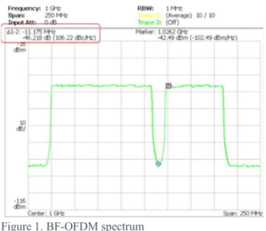
For more theoretical considerations and software simulation results about BF-OFDM, the reader is referred to [12]. In the 5G-ALLSTAR project, we aim at providing a Proof of Concept (PoC) implementation of this waveform for high data rate. The transceiver is therefore being designed in High Description Language (HDL), based on an architecture optimized for high rates (i.e. parallel design). The HDL design is implemented in the Field Programmable Gate Arrays (FPGA) of a Xilinx RF-SoC and tests are run including RF conversion. At this stage of
the project a full narrow band transmitter-receiver has been implemented (with a simple Forward Error Coding scheme), proving the feasibility of the concept of this waveform. We have also implemented the large band transmitter (200 MHz bandwidth) and we are currently working on the implementation of the large band receiver. Figure 1 shows a snapshot of the spectrum analyser at the output of the transmitter. 46 dB rejection for a band gap of 22.35 MHz could be demonstrated, as can been seen in the figure.
Figure 1. BF-OFDM spectrum
The question of the implementation of a physical layer compatible with 3GPP NR release 15 at the satellite transmitter has been raised in [3]. In this study, typical satellite implementation constraints (power amplifier response, Carrier and Sampling Frequency Offsets, output analog filtering and phase noise) were modelled and realistic channel models were used. The results demonstrate that provided that the channel does not experience long shadowing periods, a waveform such as BF-OFDM can fulfil the satellite communication requirements.
B. Beamforming-based interference avoidance
Both cellular and satellite links employ high frequency bands such as mmW bands at 22 GHz and 28 GHz or Ka-band (17.3 – 20.2 GHz, 27.0 – 30.0 GHz). In these frequency bands, narrow beams are typically used by beamforming techniques using highly directional antennas. For example, horn, slotted waveguide array, and microstrip patch array antennas are used for cellular links, and dish antennas are used for satellite links. Considering realistic antenna models, we are developing beamforming techniques by properly steering and switching the beams in order to avoid interference without sacrificing the spectrum usage.
If a UE has directional antennas with beam selection and switching capabilities, this can be used for avoiding interference between different systems such as terrestrial and non-terrestrial systems. Figure 2 shows the concept of beam selection at UE served by a satellite to avoid the interference towards another UE served by a roadside unit. Here the UE can
select one of multiple beams to maximize the signal quality while suppressing the effect of interference.
Figure 2. Beam selection for interference avoidance
In a cellular environment, beam selection has been used to find the best beam among multiple beams without considering the existence of interference. In this situation, the natural solution is to select the beam with the highest received power [13]. The received beam power can be measured using the synchronization signal block or channel state information (CSI) reference signal, both of which can support a beam sweeping operation in the time domain [14]. In other words, the beam selection is the procedure of finding beam 𝑖∗ having the maximum path loss-scaled channel power gain from the transmitter beam to the receiver beam, as given by
𝑖∗= arg max 𝑙 𝑔
where 𝑙 is the distance between the transmitter and receiver, 𝛼 is the path loss exponent, and 𝑔 is the channel power gain between the transmitter and the receiver.
The above beam selection scheme only considers the received signal power level without any consideration of interference. Here, the problem is that even though it selects the beam with higher received power, its received signal quality can be deteriorated if strong interference is also received from that beam. One solution to avoid this false-selection due to interference is to select the beam considering both the received signal power and the interference power. The interference-avoiding beam selection can be done as follows :
𝑖∗= arg max (𝑙 𝑔 (𝑟⁄ ℎ ))
where 𝑟 is the distance between the interferer and receiver and ℎ is the interference channel power gain. The interference power can be measured by the interference measurement procedure using interference measurement resources [14].
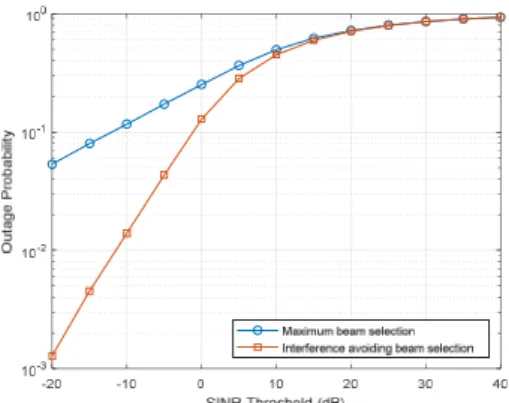
As a means of evaluating the above beam selection techniques, outage probability is employed. Outage probability is defined as the probability that the signal-to-interference-and-noise ratio (SINR) is less than a predefined threshold.
The performance evaluation is provided via simulation. The following simulation parameters are assumed: 𝑃 = 0.1 W, α = 3, and SNR = 20 dB. The antenna gain is 10 dBi and the K-factor is 9.24 dB. The outage probability is depicted as a function of the SINR threshold in Figure 3. It is observed that the interference avoiding beam selection scheme significantly reduces the outage probability as compared to the conventional maximum beam selection technique, especially in the low SINR threshold region.
Figure 3. Outage probability vs. SINR threshold
C. Radio Resource Management
5G-ALLSTAR is developing a system-level simulator that allows the simulation of interference scenarios between multiple radio access technologies (cellular and satellite) sharing the same spectrum, in C-band and millimeter bands, at a RRM level. RRM algorithms are being designed for mitigating the interference while maximizing the overall throughput and the user Quality of Service. Optimal implementation approaches in the 5G system of the joint cellular/satellite RRM is studied.
The architecture of the satellite Radio Access Network (RAN) based NR access and the terrestrial NG-RAN, for this study, is based on coordinated gNBs. The satellite gNB is split into a Centralized Unit (CU), located at the satellite gateway, and a Distributed Unit (DU) on board the satellite, connected via the F1 interface. Only one satellite is modelled. The gNB-CU and the gNBs exchange RRM related signalization across Xn interfaces. A RRM is implemented in each cellular RAN, either satellite or terrestrial. The satellite RRM is coordinated with the other RRM, in the terrestrial RAN. In order to speed up the coordination between RRMs, a centralized RRM, hosted by a master gNB takes the decision to select the schemes that the other RRM should apply, hosted by secondary gNBs. The roles of master gNB and secondary gNB can be endorsed either by on satellite gNB-CU or terrestrial gNB. An overview of the simulator is given in Figure 4. The simulator is Network Simulator 3 (NS-3) based: NS-3 is an open source platform that provides 4G / 5G RANs and 4G Core Network modules, with their source. NS-3 modules are continuously extended by adding new features, provided and tested by a wide community of developers.
In the first period of the project the priority has been given to adapt the NS-3 RAN module for frequencyies below 6 GHz to satellite link constraints. This requires the development of new NS-3 models and the adaptation of other existing ones. New models developed in 5G-ALLSTAR are for examples: longer propagation delays for satellite links, antenna models, satellite PL, satellite user link budget, NS-3 interference model adaptation per Physical Resource Block basis (satellite segment against terrestrial segments and vice versa), satellite / terrestrial
multi-connectivity for UE. Another achievement of the first year was the review and the selection of the RRM joint schemes to be implemented in the simulator. The chosen criteria were the complexity, the applicability to the space segment and the implementation constraints on the NS-3 platform. Two Full Frequency Reuse schemes were selected as reference scenarios; one with a unique band for cellular and satellite users and the other with different bands for cellular and satellite users. V. NEXT STEPS
In the next periods of the project, we will continue developing algorithms and techniques for interference management: (i) the HDL design of the full BF-OFDM large band receiver and its FPGA implementation will be completed. The transmitter and the receiver will be connected to a channel emulator and will be inserted in the cellular / satellite multi-connectivity PoC of the project. (ii) A further means to mitigate interference in the co-channel interference environment between terrestrial and non-terrestrial systems will be provided by employing interference alignment techniques. Using the CSI, interference alignment achieves a virtually interference-free transmission by aligning the interference in a specific signal space orthogonal to the desired signal, further described in [15] and [16]. However, most existing works on interference analysis have been limited to terrestrial applications. Considering the high impact of the interference between the terrestrial and non-terrestrial systems, a new interference alignment technique will be studied for mitigating the interference either in the downlink or uplink direction during the next phase of the 5G-ALLSTAR project. (iii) The RRM coordination schemes will be further studied, considering different scenarios, with respect to UE density, end-to-end traffic load conditions, satellite positions (elevation angles) and sky conditions. The targeted KPIs are SINR, Received Signal Strength Indicator, Reference Signals (RS) Received Power, RS Received Quality, and spectral efficiency per user link, for the physical level, data rate per user link at Internet Protocol (IP) level, cell data rate at IP level and global data rate provided by the satellite. Both directions will be considered: uplink and downlink.
VI. CONCLUSION
5G is being deployed around the world. Nevertheless, an effort remains to be made to finalize the integration of non-terrestrial networks into this standard. Through this paper, we have shown the work done by the 5G-ALLSTAR project during its first year, to prove that spectrum sharing between terrestrial and satellite systems can become a reality in the very short term. Over the next two years, comprehensive software simulations based on the tools developed as part of the project (beamforming, Radio Resource Management) will be conducted and hardware implementation of the waveform will
be completed. The results will enable us to propose optimized solutions for terrestrial / satellite spectrum sharing.
Acknowledgment
The research leading to these results has received funding from the European Union H2020 under grant n. 815323 and is supported by the Institute for Information & communications Technology Promotion (IITP) grant funded by the Korean government (MSIT) (No. 2018-0-00175, 5G AgiLe and fLexible integration of SaTellite And cellulaR).
References
[1] 5G-ALLSTAR website: https://5g-allstar.eu/
[2] https://ieeexplore.ieee.org/stamp/stamp.jsp?tp=&arnumber=8473416
[3] Cassiau, N., Maret, L., Doré, J. B., Savin, V., & Kténas, D. (2018, November). Assessment of 5G NR Physical Layer for Future Satellite Networks. In 2018 IEEE Global Conference on Signal and Information Processing (GlobalSIP) (pp. 1020-1024). IEEE.
[4] 3GPP; Technical Specification Group Radio Access Network, Study on new radio (NR) to support non terrestrial networks (release 15), 2018, 3GPP TR 38.811 V15.0.0 (2018-06)
[5] J. Nuckelt, M. Schack, and T. Krner, “Geometry-based path interpolation for rapid ray-optical modeling of vehicular channels,” in 2015 9th European Conference on Antennas and Propagation (EuCAP), April 2015, pp. 1–5
[6] http://raytracer.cloud
[7] ITU-R, “S.465-6: Reference radiation pattern of earth station antennas in the fixed-satellite service for use in coordination and interference
assessment in the frequency range from 2 to 31 GHz,” ITU Recommendations, Tech. Rep., 2010.
[8] Guan, K., He, D., Ai, B., Hrovat, A., Kim, J., Zhong, Z., & Kürner, T. (2018, December). Realistic Channel Characterization for 5G Millimeter-Wave Railway Communications. In 2018 IEEE Globecom Workshops (GC Wkshps) (pp. 1-6). IEEE.
[9] 5G-ALLSTAR Technical Report 3.1, “Spectrum usage analysis and channel model”
[10] Jaeckel, S., Raschkowski, L., Burkhardt, F., & Thiele, L. (2019, September). A Spatially Consistent Geometric D2D Small-Scale Fading Model for Multiple Frequencies. In 2019 IEEE 90th Vehicular Technology Conference (VTC2019-Fall) (pp. 1-5). IEEE.
[11] 3GPP; Technical Specification Group Radio Access Network; Study on New Radio Access Technology; Physical Layer Aspects (Release 14), 2017, 3GPP TR 38.802 V14.2.0 (2017-09)
[12] Demmer, D., Zakaria, R., Doré, J. B., Gerzaguet, R., & Le Ruyet, D. (2018, October). Filter-bank OFDM transceivers for 5G and beyond. In 2018 52nd Asilomar Conference on Signals, Systems, and Computers (pp. 1057-1061). IEEE.
[13] W. Roh et al., “Millimeter-wave beamforming as an enabling technology for 5G cellular communications: Theoretical feasibility and prototype results,” IEEE Commun. Mag., vol. 52, no. 2, pp. 106–113, Feb. 2014. [14] E. Dahlman, S. Parkvall, and J. Sköld, 5G NR: The Next Generation
Wireless Access Technology, Academic Press, 2018.
[15] V. R. Cadambe and S. A. Jafar, “Interference alignment and the degree of freedom for the K user interference channel," IEEE Trans. Inf. Theory, vol. 54, no. 8, pp. 3425-3441, Aug. 2008.
[16] C. Suh, M. Ho, and D. N. C. Tse, “Downlink interference alignment,” IEEE Trans. Commun., vol. 59, no. 9, pp. 2616-2626, Sep. 2011.