HAL Id: hal-02272866
https://hal.archives-ouvertes.fr/hal-02272866
Submitted on 28 Aug 2019HAL is a multi-disciplinary open access archive for the deposit and dissemination of sci-entific research documents, whether they are pub-lished or not. The documents may come from teaching and research institutions in France or abroad, or from public or private research centers.
L’archive ouverte pluridisciplinaire HAL, est destinée au dépôt et à la diffusion de documents scientifiques de niveau recherche, publiés ou non, émanant des établissements d’enseignement et de recherche français ou étrangers, des laboratoires publics ou privés.
experimental data and SPH simulations
Yann Michel, Jean-Marc Chevalier, Christian Durin, Christine Espinosa,
Frédéric Malaise
To cite this version:
Yann Michel, Jean-Marc Chevalier, Christian Durin, Christine Espinosa, Frédéric Malaise. Hyperve-locity impacts on thin brittle targets: experimental data and SPH simulations. HVIS 2005 - Hyper-velocity Impact Symposium, Oct 2005, Lake Tahoe, United States. pp.441-451. �hal-02272866�
an author's https://oatao.univ-toulouse.fr/2385
http://dx.doi.org/doi:10.1016/j.ijimpeng.2006.09.081
Michel, Yann and Chevalier, Jean-Marc and Durin, Christian and Espinosa, Christine and Malaise, Frédéric Hypervelocity impacts on thin brittle targets: experimental data and SPH simulations. (2006) In: HVIS 2005 -Hypervelocity Impact Symposium, 10 October 2005 - 14 October 2005 (Lake Tahoe, United States).
HYPERVELOCITY IMPACTS ON THIN BRITTLE TARGETS:
EXPERIMENTAL DATA AND SPH SIMULATIONS
Y. Michel(1, 2, 3), J-M. Chevalier(1), C. Durin(2), C. Espinosa(3), F. Malaise(1) (1)CEA-CESTA /DEV/SDET/LDDT – BP 2, F-33114 Le Barp
(2)CNES– BP 4025, 18 avenue Edouard Belin F-31055 Toulouse Cedex
(3)ENSICA - 1 Place Emile Blouin, F-31056 Toulouse Cedex 54. Contact : [email protected]
ABSTRACT
The meteoroids and debris environment play an important role in the reduction of spacecraft life time. Ejecta or secondary debris, are produced when a debris or a meteoroid impact a spacecraft surface. These ejecta can contribute to a modification of the debris environment: either locally by the occurrence of secondary impacts on the component of complex and large space structures, or at long distance by formation of small orbital debris. This double characteristic underlines the necessity to model the damages caused by an HVI as well as the material ejection caused by the impact. Brittle materials are particularly sensitive to hypervelocity impacts because they produce features larger than those observed on ductile targets and the ejected fragments total mass including ejectas and spalls is in the order of 100 times bigger than the impacting mass. The French atomic energy commission (CEA) faces to the same problem in the Laser MégaJoule project (LMJ). The various instruments used in the experiment chamber will undergo many aggressions resulting from target disassembly. Thus the lasers optics will be bombarded as hypervelocity debris and shrapnel. In this study, the authors only focus on potential impacts of debris and shrapnel on fused silica optical debris shields. These Main Debris Shields called MDS are 20mm thick fused silica plates placed in front of each lasers way out. 2 mm thick Disposable Debris Shields, DDS, located in front of the MDS might be used to stop vapour, particulate, droplets and substantially reduce very small shrapnel cratering on the main debris shields. But ejecta from the rear surface of the DDS and penetration through the DDS are likely to damage the MDS and seed new laser damage sites. The MDS lifetime is limited by the laser damage growth of those damage sites.
The main aim of this paper is to study the damaging and ejection processes that occur during hypervelocity impacts on thin brittle targets (dp = 500 microns for velocities ranging from 1 to 5 km/s). The two stage light gas gun
“MICA” available at CEA-CESTA has been used to impact thin fused silica debris shields and the impacted samples have been analysed with environmental SEM microscopy and perthometer. Experimental characterization of ejected matter has also been performed on the MICA facility: lightweight paperboards coated with adhesive and silica aerogel have been used to collect and characterize the ejected fragments including ejectas and spalls. The severe deformations occurring in any hypervelocity impact event are best described by meshless methods since they offer clear advantages for modeling large deformations and failure of solids as compared to mesh-based methods. Numerical simulation using the SPH method of Ls-Dyna and the Johnson Holmquist material model adapted for fused silica were performed at ENSICA. The results of these calculations are compared to experimental data obtained with MICA. Experimental data include the damage features in the targets (front and back spalled zone, perforation hole and cracks observed in the target) and the clouds and fragments ejected during the impact. Good agreement between numerical and experimental simulations was obtained for damage characteristics and ejection phenomena.
1. INTRODUCTION: COMMON INTERESTS OF CNES-ONERA AND CEA ON HVI INVOLVING BRITTLE TARGETS
The increasing willing of space companies to reduce spacecrafts cost has, in recent years, led to the development of satellites with longer operational lifetime. Increasing the longevity of satellites presents many constraints in terms of material degradation due to the space environment and many satellites undergo anomalies during their operating life. The meteoroids and debris environment play an important role in the reduction of spacecraft life time. Ejecta or secondary debris, are produced when a debris or a meteoroid impact a spacecraft surface. Three different ejection processes can be identified and are presented in figure 1:
9 Jetting: small and fast liquid particles ejected at grazing angles (MJetting < 1% of total ejected mass).
9 Cone: small and fast particles ejected at evolution angles depending on the impacting conditions. 9 Spall fragments: large fragments ejected at low velocities in a direction perpendicular to the target’s
surface. The spallation phenomenon primary concerns the brittle material and represents about 90% of the ejected mass (Bariteau, 2001) and is observed on both faces of non semi-infinite targets. Thin targets are particularly sensitive to spallation because the shock wave that reach the rear face of the target is strong enough to cause material failure.
Figure 1 Ejecta production mechanisms: jetting, ejecta cone and spalls
1.1. Role of brittle materials in space debris proliferation
Among many materials used on satellites, brittle materials are particularly sensitive to hypervelocity impacts because they are essential within the mission (they are used for optics or solar cells) and because they represent very large surfaces exposed to the debris and meteoroids environment. Moreover, as it has been highlighted by large solar arrays returned from the Eureca Mission and Hubble Space Telescope, hypervelocity impact on brittle materials produce features not observed on ductile targets. Low fracture toughness and high yield strength produce a range of morphologies including cracking, spallation and shatter. Impact features are typically characterised by petaloid spallation separated by radial cracks which extend to much larger volumes than the primary crater and subsequently remove most or all of the primary crater, especially for thin targets. Thus, because of both large surface exposure and large damaged volume, a great number of fragments are ejected at high velocities and brittle materials play a very important role in the potential degradation of the space environment. As it has been reported by Bariteau and Mandeville (Bariteau, Mandeville et al, 2001), the ejected volume can be 100 times higher than the impacting volume in the case of brittle targets and some spalls are much bigger than the incoming particle. Such ejected mass and volume primary concerns rear impacts and illustrates the sensitivity of brittle materials to spallation and the interest of thin targets that are the most damaging ones for both the target itself and the debris environment. This underlines the importance of understanding the damaging and ejection processes on both faces of thin brittle targets for a better comprehension of modifications of the debris environment on earth orbits.
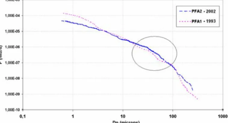
Some recent evolutions of the debris and micrometeoroids population reported by Moussi et al (Moussi et al, 2005) after analysis of Hubble solar arrays retrieved in 2002 underline the danger of this auto generation phenomenon. Figure 2 illustrates an increase in the total cumulative objects flux since 1993 which highlights an important raise of objects between 15 and 100 microns in diameter. This rise is mainly due to space debris but has to be normalised by the solar activity during the two periods. Indeed, the mean atmospheric density decreased from 1993 till 2002 so further studies are leading in order to determine if the population is only stabilised or increasing. According to the size range of these objects, it is probably due to secondary debris such as spalls. As the life time of such fragments does not exceed 10 days to a year, the secondary debris generation process needs to be much important to stabilise or increase the debris population. This observation underlines the interest to improve knowledge of the ejecta phenomenon and capabilities to model material ejection occurring during hypervelocity impacts on thin brittle targets.
Figure 2 Increase in objects cumulative fluxes observed in 1993 and 2002. The fluxes are calculated from HST solar arrays retrieved from space in 1993 and 2002 (Moussi et al, 2005).
1.2. Role of brittle materials in the Mega Joule Laser (LMJ) project
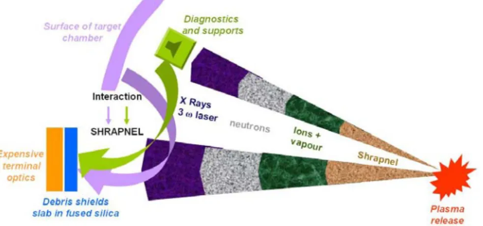
The LMJ is one of the large experimental facilities of the Simulation program designed to ensure ongoing deterrence without resorting to nuclear testing. The high-powered laser will be built at the CEA-CESTA (study centre under the Atomic Energy Commission's Military Applications Directorate) facility. Its 240 beams will focus 1.8 megajoules of energy on a target placed in a vacuum at the centre of an 11 metre diameter test chamber. The various instruments used in the experiment chamber will undergo many aggressions resulting from target disassembly. Thus the large lasers optics will be bombarded by X-rays, neutrons, ions as well as debris and shrapnel. In this study, the authors
will only focus potential impacts of debris and shrapnel on fused silica optical debris shields.
Figure 3 Aggressions underwent by LMJ experiment chamber and interactions between target and diagnostics disassembly and brittle debris shields
1.2.1. Protective optics of the LMJ experiment chamber
The Main Debris Shields called MDS are 10mm thick fused silica plates placed in front of each of the 240 lasers way out. 2 mm thick fused silica Disposable Debris Shields, DDS, located in front (eventually with incidence) of the MDS might be used to stop vapour, particulate, droplets and substantially reduce very small shrapnel cratering on the main debris shields. But ejecta from the rear surface of the DDS and penetration through the DDS are likely to damage the MDS and seed new laser damage sites. The MDS lifetime is limited by the laser damage growth of those damage sites.
As it has been presented above, CEA is concerned by damages caused by hypervelocity impacts on thick brittle targets (10 mm thick Main Debris Shields) and on thin brittle target (DDS) located in front of these MDS. As fragments generated during an LMJ shot can perforate the DDS plate and/or generate secondary fragments that may impact MDS or will simply pollute the experiment chamber, CEA is also concerned by secondary debris generation as well as CNES is concerned by spalls and ejecta ejection in the space environment.
1.2.2. CEA’s experimental facility: MICA double stage light gas gun
Nowadays experimental data on hypervelocity impact are essential to observe and understand the phenomena that occur during the impact and they allow validating numerical simulations. To lead the LMJ study, CEA-CESTA has built a two stages light gas gun called MICA able to launch 2 mm projectiles at 5 km/s (figure 4). All the MDS and the DDS presented in this article where impacted by MICA with either 500 microns steel or glass projectiles. The following part presents the results of fused silica MDS/DDS post impact analysis (CEA-CESTA).
2. ANALYSIS OF IMPACTED SAMPLES 2.1. Thick brittle targets: 1cm MDS
The first sample family concerns MDS plates impacted at CEA by MICA. MDS are 10mm thick fused silica plates. They were impacted by 500µm glass or steel projectiles at velocities ranging from 0.5 to 5 km/s. High velocity damage in MDS results in front side craters with large diameter relative to crater depth and internal flaws. These craters have circular pattern contours in outer regions; these patterns result from both internal cracks and surface spallation. A center area of heavier damage has also been observed and appears white on front-lit views (cf. figure 5). This area consists of a central pit showing the footprint of the projectile and a shattered zone at the periphery of the pit. The shattered zone is probably due to SiO2 fragmentation and compaction during the shock loading as reported by Cagnoux (1985). No
evidence of projectile residue was found on MDS samples for both glass and steel projectiles even inside the fragmented volume of the crater, it is suspected that the projectile is retro ejected during the impact. Figures 5 and 6 illustrate observations made above. In some high energy cases, rear spallation without material ejection was observed on MDS. Adding this to the large damaged area and its potential effects on laser fluence incited CEA to investigate MDS protection with thin DDS. DDS damage will be the object of part 2.2.
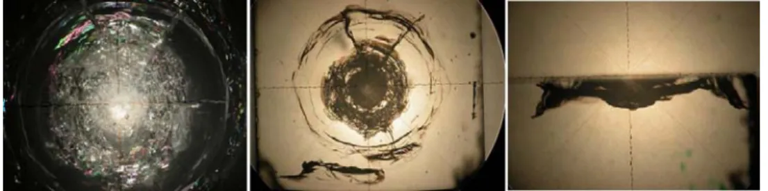
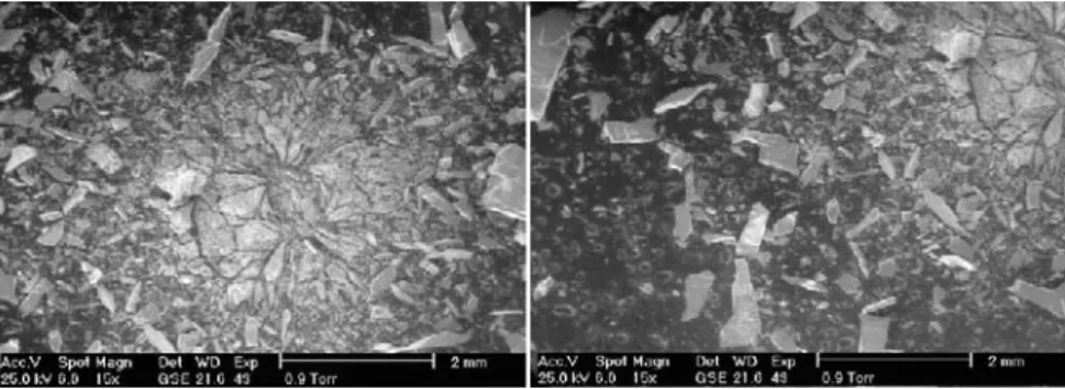
Figure 5 Damages observation caused by a HVI on a MDS at 2745 m/s. The left view is a front-lit view and shows the compaction area, the middle and right picture are back-lit view internal sample’s damages
Figure 6 SEM view of a MDS impacted at 2745 m/s by MICA. The picture shows the different damages zone: the central pit, the compacted zone and the spall zone.
2.2. Thin brittle targets: 2mm DDS
The case of thin brittle targets is particularly interesting for two main reasons. First of all, as it has been presented earlier, solar cells which behave like thin brittle targets are the constitutive elements of solar arrays and they represent at the same time very large surfaces exposed to the space environment and a source of secondary debris. The second reason is related to the quantity of ejected matter during hypervelocity impact. Spall phenomenon is indeed the main source of ejection for any brittle target; further more, as it has been observed on impacted DDS, spallation occurs at the front face and rear face of the sample even if there is no perforation (figure 8 and 10). This characteristic is particularly important for HST solar cells for which the ejected volume for rear impacts can be as much as hundred times higher than the impacting particle volume, as reported after HST-CS analysis performed at CNES and ONERA.
The case of DDS designed to be used in the LMJ experiment chamber illustrates perfectly potential problems and danger caused by thin brittle targets: the question which should be raised consists in knowing if we will not generate more fragments while trying to protect the MDS. If cost effective DDS are necessary to protect MDS, what is the best configuration in terms of incidence and distance between DDS and MDS to avoid seeding to much damage in the MDS. To answer this, a MICA shooting campaign has been started in summer 2004 to study damages caused by HVI in DDS and potential damages caused by rear face matter ejection on MDS. Many 2mm thick DDS were impacted by glass and steel projectiles (Ø=500µm) for velocities ranging from 1000m/s to 3500m/s. As for thick targets, damages consist of three main characteristics: a perforation hole (Dh ≈ 2.5mm) or a central pit, a shattered zone (also called compacted
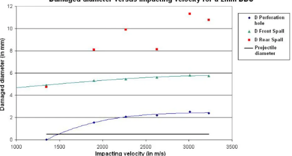
zone) and a wide spallation zone (figure 7). What was new on thin target is that these characteristics were observed for both front and rear faces (figure 8). Figure 7 illustrates the damages observed on a DDS, the shattered zone is limited to close hole’s periphery whereas the spall zone extends to a much larger surface (figure 8 and 9). In all perforating cases, as it can be seen on figure 9, the spallation zone on the rear face (DSpall Back ≈ 8-11mm) is almost twice the one observed
ranges from 1.5mm to 2.5mm and seems to stabilise around 2.5mm for velocity higher than 2.5 km/s. The front spalled diameter does seem sensitive to the impacting velocity. The situation of the rear spalled diameter is quite different because it increase with an increase velocity, the reader must notice that there is a large data dispersion due to radials cracks observed on the rear face (figure 8).
Figure 7 SEM view of a DDS impacted by MICA at 3.2 km/s. The picture shows the different damage zones: the perforation hole, the compacted zone and the spall zone
Figure 8 Two faces of the same 2mm DDS impacted at 1.9 km/s. The same damage characteristics have been observed on both faces the samples even in non perforating impacts but in most of the cases the rear spalled area extend to much larger surface than the front spalled area. The rear face damages are also characterised by numerous radials cracks
that cause a large data dispersion in diameters measurements.
Figure 9 Impact velocity effects on the main damage characteristics: the damaged diameters are huge compared to the projectile diameter (DDamage > 16 DProjectile for perforating impacts) rear spalled diameter is almost twice bigger than
the front spalled diameter for perforating impacts. The front spalled diameter does not seem very sensitive to the impacting velocity whereas the rear spalled diameter appears to increase with an increasing velocity.
3. EXPERIMENTAL CHARACTERISATION OF EJECTED MATTER
As it has been presented in introduction, the main threat for the space environment as well as for optics of the LMJ experiment chamber is the material ejection due to HVI on thick and thin brittle targets. Not many data on material ejection involving brittle targets are available in literature. ONERA/DESP has been working since the 90’s and has identified front face ejection tendencies occurring during HVI on brittle targets but few experimental tests were devoted to this phenomenon (Bariteau & Mandeville, 1999, 2001). Since 2004, CEA has concentrated part of its work with MICA launcher to characterise material ejection during HVI on 2mm DDS. Impacted sample were scanned with a perthometer to compute the ejected volume and two main collection setups were used and will be presented in this part: simple light paperboard coated with adhesive were placed in MICA chamber behind and around the DDS and aerogel
collectors were designed to collect fragments ejected at the rear face of the DDS.
3.1. Ejected masses and volumes
Four representative samples were analysed with a perthometer to determine their topographical profile after impact (figure 10 and 11) and to calculate the total volume/mass ejected during the impact. Volume or mass considerations depend on the related application: mass measurement are important for shielding and for space environment degradation because the most wanted output is the ejected kinetic energy but data on the ejected volume are particularly important for closed environment such as the LMJ experiment chamber. The results obtained for analysed DDS are gathered in table 1 and the two best representative cases are those presented in figure 10: a non perforating impact at 1.35 km/s and a perforating impact at 3.01 km/s. For the non perforating case, the total ejected mass is about 48.8 mg for a 4 mg steel projectile (MEjected/MImpacting = 12 and VEjected/VImpacting = 42) about 70% of this mass is due to rear spallation. The
perforating case is worth, the total ejected mass is about 71 mg (MEjected/MImpacting = 17.5 and VEjected/VImpacting = 62) and
about 90% of this mass is due to rear spallation. The mass distribution as well as the importance of Mass/Volume ratios are in total agreement with the main tendencies observed on HST solar cell by Moussi and Mandeville: on such cells the volume ratios can reach 100 and the most damaging impacts are rear impact (on HST-CS composite substrate) because they produce the largest features observed on the glass side of the cells. Such impacts are the most dangerous for both, the cell itself and the space environment.
Figure 10 Perthometer measurements of two DDS profile after impact of a 500 microns steel projectile: a non perforating impact at 1.35km/s (left) and a perforating 3km/s impact (right). These profiles illustrate the importance of
rear spallation phenomenon. Such results were used to calculate the ejected volume.
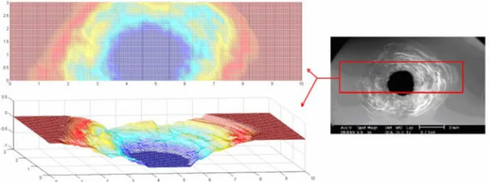
Figure 11 3D topographical profile of the front face of a 2mm DDS impacted at 2.6 km/s and its corresponding SEM view.Such results have been obtained with a Mahr perthometer available at ENSICA.
Table 1 Computed ejected masses and volumes for three impact tests at respectively 1.35, 1.9, 2.2 and 3.01 km/s (500microns steel projectiles on 2mm fused silica DDS). This table illustrates the potential danger of rear face effects when a thin target is impacted at high velocity: the ejected masses and volumes much bigger than the impacting mass and volume and at least 60% of this mass is due to rear spallation even in non perforating cases.
Projectile characteristics Projectile mass ≈ 4mg - Projectile volume ≈ 0.52 mmMaterial: steel - Dp = 500 µm, 3
Shot 08-05 07-05 04-05 06-05
Impact velocity 1350 m/s 1900 m/s 2200 m/s 3010 m/s
Front ejected mass 15.5 mg (31.7 %) 17.3 mg (38.9 %) 13.5 mg (24 %) 9 mg (12.6 %)
Rear ejected mass 33.3 mg (68.3 %) 27.2 mg (61.1 %) 42.7 mg (76 %) 62.3 mg (87.4 %)
Total ejected mass 48.8 mg 44.5 mg 56.2 mg 71.3 mg
Mass Ratio
(Ejected Mass / Impacting Mass) 12 10.9 13.8 17.5
Total ejected volume 22.1 mm3 20.2 mm3 25.5 mm3 32.4 mm3 Volume ratio
3.2. Secondary impacts and collected fragments
Knowing the total ejected mass is very important to assess the potential damages caused by rear ejection on secondary optics but complementary data on the ejected fragments and on their ejection velocity need to be collected. For this reason, light paperboard (PB) coated with adhesive have been used on MICA facility and appeared to be an excellent and cost effective fragments collector. Many paperboard plates were disposed around and behind the impacted DDS. Figure 12 is a SEM view of a PB located 25mm behind a perforated DDS at 2.6km/s.
Figure 12 Fragments collected on paperboard located behind the perforated DDS impacted by MICA
As it can be seen on the figure many large fragments were generated by the impact. Three main areas have been identified: a 3 mm in diameter central area showing spalls probably deteriorated during the secondary impact on the paperboard, a peripheral zone made of micro fragments (typical size = 10–50 µm) extends up to 5mm in diameter and a third wide zone extending up to 6.5mm from impact axis is made of long parallelepiped fragments whose typical dimensions are 1x0.1x0.1mm. Relating these different fragments category to their supposed origin and to damages observed on the corresponding DDS is not an easy task. We can nevertheless make some hypothesis: the micro fragments seem to correspond in size with those observed on DDS and may result from fragmentation of fused silica during shock loading. The long parallelepiped fragments probably originate from spallation observed on the rear face of impacted samples. In some cases, similar non-ejected fragments were observed on DDS. The origin of the central area is more difficult to identify because fragments have been probably deteriorated and no projectile residue have been found. The most supposed origin is an important central spallation occurring at the DDS rear face. Knowing the distance from the paperboard to the DDS, diameters of these areas have been used to determine the ejecta clouds geometry: central spall and micro fragments have quasi normal ejection angle (respectively 3.6° and 5.9° from the shooting axis) and parallelepiped fragments have an ejection angle lower than 15°. The reader must notice that these results are consistent with order of magnitude given by ONERA’s environmental model which expect nearly nomal ejection for spalls (Mandeville & Bariteau et al, 1999, 2001).
According to the results presented above, light paperboards appear to be interesting collection diagnostics and allow determining ejection clouds geometry. But fragmentation during secondary impact makes them limited for swift shrapnel. This observation incites the authors to investigate the use of aerogels as shrapnel collectors.
3.3. About the use of aerogels
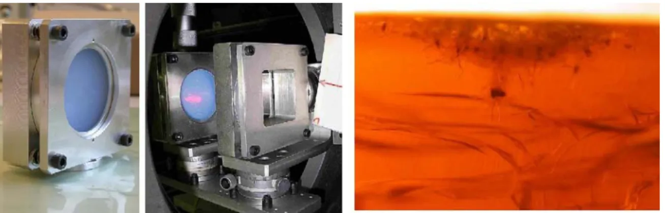
With the sight of performances of aerogels in terms of hypervelocity particles collection (cf. MEEP experiment), the use of such materials appears to be an excellent way to characterise matter ejection during HVI on brittle target. Numerous cylindrical aerogel blocks were manufactured by the french company PrimeVerre. Blocks were 20mm high and 60mm in diameter; their density was 0.1 g/cm3. Collection of front and rear ejected fragments have been planned
using aerogel, the collection setup and picture of front bored aerogel sample produced by PrimeVerre are illustrated in figure 13. At the time of this paper, only rear face collection has been performed for practical reason. These samples were sized with collected fragments and the clouds geometry computed from paperboard collection and with results of SPH numerical simulations and ONERA environmental model for ejection velocities. Two different penetration models have been used to size aerogel samples, the first one derived by Dominguez et al was used to size the penetration depth of spherical glass particles in silica aerogel (Dominguez et al, 2004) and the second one, more adapted for spalls, derived by Tobin et al was used to size the penetration depth of spalls in silica aerogel (Tobin et al, 2003). These two penetration models predict highly different penetration depths for the two types of projectile impacting the aerogel at moderate velocities (V ≈ 1 km/s). Figure 14 illustrates the predicted depth for a 50 microns projectile for velocity ranging from 0.1 to 1.5 km/s. As the sizing case determined as presented above was a 50 microns spherical projectile at 1.5 km/s the typical thickness of the blocks was 20mm. Right pictures of figure 13 illustrates the collection setup used on MICA facility, this setup allows to maintain aerogel integrity during vacuum setting and fragment collection. Left picture of figure 15 shows an aerogel block in its box as it has been integrated into MICA experiment chamber. The right picture is a back-lit view of fragments collected in the aerogel after a 3 km/s impact on a 2mm DDS. Analysing silica aerogel and localising silica fragments in it are challenging tasks. Optical observation was the main method used but many options are being studied. As it can be seen on the picture shrapnel’s depth of penetration ranges from 2 mm to 6 mm which are values less than those expected by Dominguez et al analytical models but it fits closer the simple snowplow model (Tobin et al) (figure 14). As it can be seen on figure 15, a bigger fragment has been identified and penetrated much deeper in the sample (6 mm); according to the different penetration depths between this fragments and other fragments it is suspected that it is made of steel projectile residue. Many reasons can explain the relative low
penetration depth: the ejection velocity has been overestimated by numerical simulation, either shape effects are prevalent or penetration analytical model are not adequate in these cases. To locate precisely the collected fragments, X-ray radiographies have been performed at CNES and gave encouraging results (figure 16): fused silica fragments have been located in silica aerogel using the density differences between both materials. Such a technique is necessary to compute precisely ejection velocities and will be used for 3D X-ray tomography in the following months.
According to these results, aerogel setups appeared to be new promising collection systems which could give 3D topology of the matter ejected from both faces of the target especially for very high impact velocities. As aerogel collectors have proved their ability to collect “intact” high velocity fragments, such collection setup will continue to be used on MICA facility.
Figure 13 Aerogel collection setup (right picture) and bored aerogel sample manufactured by PrimeVerre (left picture)
Figure 14 Predicted penetration depth obtained using Tobin et al and Dominguez et al models for typical 50 microns spherical ejectas and spalls. The chosen sizing case was a 50 microns spherical projectile at 1.5 km/s.
Figure 15 Aerogel collector used on MICA launcher (left and middle pictures) and collected ejecta and spalls (right) for a 3 km/s impact on a 2mm DDS
4. NUMERICAL MODELLING OF HVI ON THIN BRITTLE TARGETS WITH THE LS-DYNA SPH METHOD
Recent work realised by the authors (Michel, 2003) focused on HVI on thin ductile target and have proved the ability of the Ls-Dyna SPH method to reproduce damage mechanisms as well as matter ejection (more particularly ejection angles and velocities). After a brief presentation of the SPH method and the Johnson Holmquist material model, this section presents the simulations results of hypervelocity impacts of steel projectiles on 2mm fused silica DDS. Validation criteria as well as prediction capability of the code will be assessed.
4.1. Ls-Dyna Smooth Particle Hydrodynamics method
Smoothed Particle Hydrodynamics (SPH) method is a grid less Lagrangian technique that originated in 1977. The main advantage of the method is to bypass the requirement for a numerical grid to calculate spatial derivatives. This avoids the severe problems associated with mesh tangling and distortion which usually occur in Lagrangian analyses involving large deformation impact and explosive loading events. Grid based methods such as Lagrange and Euler assume connectivity between nodes to construct spatial derivatives. SPH uses a kernel approximation which is based on randomly distributed interpolation points with no assumptions about which points are neighbours to calculate spatial derivatives. To illustrate this consider a continuum represented by a set of interacting particles, as shown in figure 17. Each particle I interacts with all other particles J that are within a given distance (usually assumed to be 2h) from it. The distance h is called the smoothing length. The interaction is weighted by the function W(xi-xj,h) which is called the smoothing (or kernel) function. Using this principal, the value of a continuous function, or its derivative, can be estimated at any particle I based on known values at the surrounding particles J using the following kernel estimates:
j j i j i
f
x
W
x
x
h
dx
x
f
>≈
∫
−
<
(
)
(
)
(
,
)
<
∇
•
f
(
x
i)
>≈
∫
∇
•
f
(
x
j)
W
(
x
i−
x
j,
h
)
dx
j (1)where f is a function of the three dimensional position vector xi, dxj is a volume and W, the smoothing function, can be expressed as follow. θ. is an auxiliary function. The most commonly function used by the SPH community is the cubic B-spline which has some good properties of regularity.
−
=
−
h
x
x
h
h
x
x
W
(
i j,
)
1
θ
i j (2) with( )
> ≤ < − ≤ + − × = 2 0 2 1 ) 2 ( 4 1 1 4 3 2 3 1 3 3 2 y for y for y y for y y C y θ (3)where C is the constant of normalization that depends on the space dimension.
Figure 17 Neighbouring particle geometry and computational cycle for SPH methodology in Ls-Dyna
Particle approximation of function
After several steps of derivation and by converting the continous volume integrals to sums over discrete interpolation points the equations can be expressed in several forms, with commonly used symmetric formulations for the gradient being. Ls-Dyna formulation can be expressed as follow:
)
,
(
)
(
)
(
>=
∑
−
<
j j i j j j if
x
W
x
x
h
m
x
f
ρ
(4)The approximation of gradients is obtained by applying the derivation operator on the smoothing length.
) , ( ) ( ) ( >=
∑
∇• − • ∇ < j j j i j j i f x W x x h m x fρ
(5)The equations of conservation governing the evolution of mechanical variables can be expressed as follow: ij j N j j i i divv x m v x vx A x dt d )) ( ) ( ( )) ( ( ) ( 1 − = ⋅ − =
∑
= ρ ρ (6) ji j i ij N j i j j i i i i A x A x m t x x t x dt dv 2 1 2 ) ( ) ( ( )) ( ( ) ( 1 )) ( ( ρ σ ρ σ σ ρ αβ αβ αβ α − = ∂ ∂ =∑
= (7) ij i j N j j i i i i m v x v x A P x v P x dt dE )) ( ) ( ( ) ( ) ( 1 2 − − = ∇ − =∑
= ρ ρ (8) where
−
′
=
+h
x
x
h
A
ij1
d 1θ
i j , xi is the spatial coordinate of particle i. Calculation CycleThe basic steps of SPH method used in Ls-Dyna are present in figure 17. The calculation cycle is similar to that for a lagrange computation except for the steps where a kernel approximation is used. Ernel approximations are used to compute forces from spatial derivatives of stress and spatial derivatives of veloctiy are required to compute strain rates. In addition SPH requires a sort of the particles in order to locate current neighboring particles (« Neighbors search »).
4.2. Johnson Holmquist 2 material model
Johnson and Holmquist have presented two closely related constitutive models for brittle materials. The calculations presented in this study were obtained using the JH2. The model includes a representation of the intact and fractured strength, a pressure to volume relationship (equation of state) that can include bulking and a damage model that transitions the material from an intact state to a fractured state. The normalised equivalent stress for the strength is given by:
(
* *)
* * f i iD
σ
σ
σ
σ
=
−
−
(9) where HEL σ σ σ*= , HELσ
is the equivalent stress at the Hugoniot elastic limit (HEL), D is the damage (0<D<1),*
i
σ
is the normalised intact strength and *f
σ
is the normalised fractured strength. According to flyer plate impacts realised at CEG (Cagnoux, 1985), the yield stress envelope does not seem to increase much after HEL. For this reason, a maximum yield stress has been definied ( *iMax
σ
). These strengths can be written as follow:(
) (
)
* max * * * * 1 ln i N i AP T C ε σ σ = + + & ≤ (10)( ) (
)
* max * * * 1 ln f M f B P Cε
σ
σ
= + & ≤ (11) with HEL P T T*= ; HEL P P P*= and 0 * ε ε ε & && = with ε&0= s1 −1 which are respectively the normalised maximum tensile pressure, the normalised pressure and the dimensionless strain rate. The material constants are A, B, C, M, N, T and
σ
*fmax. The hydrostatic pressure before fracture is calculated using a polynomial equation of state. The bulking effect is included by adding an incremental pressure ∆P. To simulate the rupture, particles are desactivated at a pressure cut-off (P=-150MPa). This way of creating discontinuities is the most effective as it has been reported by (Mandel et al, 1996). All the results presented below use a JH2 set of parameters calibrated on shock experiment realised by Cagnoux (1985) on Pyrex glass and on data of the material model used at CEA-CESTA for fused Silica.4.3. Numerical simulations of HVI on 2mm DDS: comparison with experiments
The calculations presented in this section concern normal hypervelocity impacts involving steel projectiles on 2mm DDS at velocities ranging from 1 to 4 km/s. A 3D quarter model has been built to decrease computational time and uses two sph symmetry planes. In order to mesh the plate with an efficient way, we have divided it into two parts with different mesh densities: a total of about 210.000 particles were used for 2mm DDS. Damages (perforation hole and spalled diameters) and matter ejection have been analysed respectively to validate the method and to assess the prediction capability of the code.
4.3.1. Damages caused by impacts on 2mm DDS: Validation
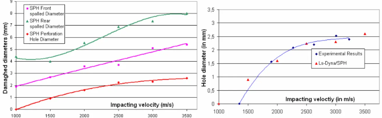
In term of qualitative results, Ls-Dyna/SPH and JH2 model provide the same damage characteristics presented in section 2 (front and rear spalls, perforation hole) are also observed in the simulation results. On a quantitative point of view, the simulations show good agreement with experiments. The effects of projectile velocity on the perforation hole are well reproduce as shown on figure 18. The velocity at the ballistic limit for a 500 µm diameter steel projectile is around 1300m/s; this value is consistent with samples analysis impacted by MICA. In term of spalled diameters, the numerical simulations seem to underestimate both spalled diameters when looking at profiles observed with the perthometer and the MEB, a very thin (e ≈ 50 microns) spalled “crown” is visible and is more important for DDS rear
faces as illustrated on figure 19. This “crown” does not represent a large volume of matter and knowing the difficulty of the SPH method for treating free boundary surfaces, a logical way for comparing experimental results and SPH simulations is to correct the spalled diameter by removing the thin spalled “crown”. Figure 20 illustrate the comparison between corrected spalled diameters and numerical simulations: good agreement was found for the rear spalled diameter whereas the front spalled diameter is still underestimated. Figure 21 is a superimposition of a perthometer profile with one obtained with the same intial conditions (V = 3 km/s), it illustrates the good agreement between SPH simulations and experimental results. The relative importance of front and rear spallation is also consistent in terms of height of the spallation zones (800µm/1200µm).
Figure 18 Damaged diameter obtained with Ls-Dyna SPH simulations (graph on the left) and comparison of perforation hole diameters obtained with numerical simulation and experiments (graph on the right) for impacts
involving 500 microns steel projectiles at velocity ranging from 1 to 3.5 km/s on 2mm DDS.
Figure 19 Illustration of the thin spalled « crown » surrounding the main spalled zone. Such observation coupled to the difficulties of the SPH method to treat free boundary surface motivated the authors to correct the measured spalled
diameters for comparing them to the numerical results
Figure 20 Comparison between measured corrected spalled diameters and numerical simulations for impacts involving 500 microns steel projectiles at velocity ranging from 1 to 3.5 km/s on 2mm DDS. The graphs underline the good agreement between SPH simulations and experimental data for rear spalled diameters but front spalled diameter are
Figure 21 Comparison of profiles obtained with Ls-Dyna and after sample analysis (black curve) showing the good accordance between both results.
4.3.2. Prediction capability of the code for matter ejection during HVI on 2mm DDS
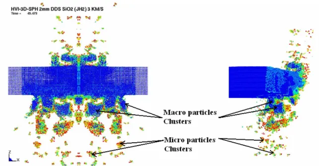
The readers must notice that the authors have extrapolated particles clusters as fragments. The clusters results from contact loss between particles mainly due to desactivation of border particles. Identifying discontinuities and rupture criteria is a challenging task with the SPH method and this is part of ongoing research activities at ENSICA/DGM. In the case of a 3km/s impact on a 2mm DDS, three types of them can be identified: ejecta, micro spalls and macro spalls. Ejecta consist of isolated and/or totally fractured particles (Ø<50µm). Their ejection velocities range from 250 to 1000 m/s for a 3km/s impact. Micro and macro spalls families consist of particles clusters of different sizes (cf. figure 22): the micro spalls are typically 400x400x100µm fragments whereas macro spalls are typically 1500x1000x60µm spalls. Their ejection velocities range respectively from 60 to 170 m/s for micro spalls and from 15 to 40 m/s for macro spalls. All these fragments are present on both faces of the DDS. In terms of clouds geometry, a conical cloud is observed on the front face during the first 10µs of the simulation then the spalls are ejected perpendicularly the main plane of the DDS: their angle of ejection from the normal of the DDS range from -5° to +5°. On the rear face of the DDS, ejecta are ejected along the normal of the DDS (α<5°) and spalls have ejection angles ranging from 5° to 15°. All these results are consistent with the analysis of the paperboard collector (cf. part 3.) and with ONERA environmental model (Bariteau, Mandeville, 2001). For a velocity range of 1 to 4 km/s, no significant effects of projectile velocity on ejection velocities have been observed.
Table 2 Predictions of the Ls-Dyna SPH simulations in terms of matter ejection for an impact at 3 km/s on a 2mm DDS Type of cluster Desactivated particles Small clusters Big clusters
Corresponding fragments Ejecta Peripheral small spalls Main spalls
Typical Size ~ 50 µm ~ 400 µm Millimetric
Velocity 250–1000 m/s 60-170 m/s 15–40m/s
Ejection Angle
(measured from the axis perpendicularly to the target) 5° [5°; 15°]
4.4. Numerical investigation of target thickness effects on damages and matter ejection: SPH simulations of HVI on 0.7, 1.1 and 2 mm DDS
The calculations presented in this part concern normal hypervelocity impacts involving steel projectiles on 0.7, 1.1 and 2mm DDS at velocities ranging from 1 to 4 km/s; no experimental data were available at this timebut the reader mst notice that they are necessary for validation. On all targets, an increasing impact velocity increases the damages seen by the different plates as it has been identified for 2mm DDS. 0.7 and 1.1mm DDS were perforated for all simulations (V>1km/s), this underlines the loss of ballistic performance by using thinner disposable debris shields. In terms of thickness effects, the perforation hole diameter ranges from 1 to 3mm and no significant differences between the 0.7, 1.1 and 2mm DDS were observed. Concerning the spalled diameters, these dimensions increase with the target thickness. For example, the front spalled diameters are respectively 3.5, 3.8 and 5.1mm for 0.7, 1.1 and 2mm DDS impacted at 3km/s, the corresponding rear spalled diameters are 4.6, 5.7 and 7.4mm. The direct consequence of such observation is the increasing ejected volume on both targets faces with an increasing DDS thickness. Figure 23 illustrates the damages seen by the different DDS impacted at 3 km/s. Ejection velocities of ejected fragments (ejecta and spalls) calculated with Ls-Dyna/SPH for DDS impacted at 3 km/s are gathered in table 3. The main effect of target thickness observed in these cases is the increasing ejecta velocity with a decreasing DDS thickness: rear ejectas reach 2.1 km/s for a 0.7mm DDS where such velocity was about 1 km/s for 2mm DDS; similar results were obtained for front ejectas with lower ejection velocity (average of 1km/s). The case of spalls is different, their ejection velocities range from 15 to 280 m/s but no significant tendency were observed in the simulations. The reader must notice that such ejection velocity might be affected by the behaviour of sph particles at the rear surface.
In conclusion, thinner DDS are less protective in terms of ballistic limit but according to numerical simulations and when looking at damages seen by the plates, hypervelocity impacts with same initial conditions generate less fragments for thinner DDS. On the other hand the mean ejecta velocity increases with a decreasing DDS thickness for ejecta on both faces of DDS. Spalls velocity did not appear to be influenced by DDS thickness. Choosing between 0.7, 1.1 and 2mm DDS for optimize protection is a challenging task and compromises between ejection velocity and ejected volume need to be made; tilting thinner DDS to increase the ballistic limit seems to be an attractive solution and many efforts will be devoted to realise incident experiments and the corresponding numerical simulations.
Figure 23 Effect of target’s thickness on damages seen by the plate: from left to right, plastic strain of 0.7, 1.1 and 2mm DDS impacted at 3 km/s by a 500 microns steel projectile.
Table 3 Comparison of ejection velocities of fragments calculated by Ls-Dyna/SPH for 0.7, 1.1 and 2mm DDS impacted at 3km/s by a 500microns steel projectile: ejecta velocity increases with a decreasing DDS thickness whereas thickness appears to have less effect on spalls velocities.
0.7 mm DDS 1.1 mm DDS 2 mm DDS
Ejecta Max: 1500 m/s Max: 1250 m/s Max: 800 m/s
Front
ejection Spalls Min: 40m/s Max: 100m/s Min: 30m/s Max: 150m/s Min: 15-50m/s Max: 80m/s
Ejecta 2100 m/s 1650 m/s 1000 m/s
Rear
5. CONCLUSIONS AND PROSPECTS
This article presents the work resulting from collaboration between three research laboratories involved in hypervelocity impacts for two different strategies. Both of concerned activities worry about material ejection during HVI on brittle targets. This collaboration leads to the construction of an important database on damages seen by brittle targets during hypervelocity impacts. The case of thin brittle targets has been highlighted as the most critical for the space environment because all damages and particularly spallation occurs on both faces of the target. Rear spallation is indeed more important than front spallation and represents more than 80% of the total ejected mass for velocities above 1.5km/s. These remarks motivated the authors to assess damages and matter ejection in simple thin SiO2 targets before considering complex multilayered structures like solar cells. Experimental techniques have been used to collect and characterise matter ejection occurring during HVI on thin brittle targets. The use of silica aerogel as laboratory collector is a very promising technique for determining ejection velocities. These collection setups allow determining types of ejected fragments and general tendencies of rear matter ejection. In this paper, the authors have also shown the capabilities of the Ls-Dyna mesh free SPH method coupled with the JH2 material model. Simulations of HVI on 2mm thin brittle plates at velocities ranging from 1 to 4 km/s give results that are in good correlation in terms of damages let in the target: perforation hole and spallation zones were reproduced with very satisfying results. In terms of matter ejection, numerical simulations appear to predict in a satisfactory way ejection velocities and corresponding fragments. Difficulties in identifying clusters of particles as fragments comfort the authors to improve material model criteria and the sph method especially for spallation and creation of discontinuities. The satisfying results obtained for 2mm DDS motivated the authors to investigate numerically thickness effects on damages and matter ejection. 0.7 and 1.1mm targets produce less fragments, spalls have ejection velocities in the order of magnitude of those calculated with 2mm DDS but their ballistic limit is lower and ejecta velocity increases with decreasing thickness. Such tendencies need to be validated by experiments.
Our future work will consist in experimentations of oblique impacts and thinner DDS (CEA-CESTA) with corresponding numerical simulations and ejecta/spalls collection. Higher velocity (6-8km/s) on DDS are also planned and fragments collection on both faces of the target using aerogel will be carry on for all these experiments. With the sight of space applications, numerical simulations of HVI on Hubble solar cells is being performed at ENSICA using JH2 material model and Ls-Dyna SPH method. These simulations will be compared with cells analysis performed by ONERA.
6. ADKNOWLEDGMENTS
The authors would like to thanks Laurent Duffours (PrimeVerre) for manufacturing aerogels collectors and for his advice during experimentations, Jean-Claude Mandeville and Aurélie Moussi (ONERA-DESP) for their advices concerning the use of brittle materials for space applications and Michel Labarrère and Daniel Boitel (ENSICA) for their help during samples analysis.
7. REFERENCES
- M. Bariteau, J.C. Mandeville, A modelling of ejecta as a space debris source, ESOC, Darmstadt, Germany, 19-21 March 2001, ESA SP-473, October 2001
- M Bariteau, Prolifération des débris orbitaux : production et évolution des particules secondaires, Thèse de l’Ecole Nationale Supérieure de l’Aéronautique et de l’Espace, 2001
- I. Bertron, J-M. Chevalier, F. Malaise et A. Barrio : Impacts hyper véloces sur la silice fondue du LMJ 5ème HDP, Saint-Malo 2003
- Dominguez G, Westphal A.J., Jones S.M., Phillips M.L.F. (2004), Energy loss and impact vratering in aerogels : theory and experiment. Icarus (in press) 2004
- J. Cagnoux, Déformation et ruine d’un verre pyrex soumis à un choc intense, these dee l’université de Poitiers, 1985. - J.L. Lacome, Smoothed particles hydrodynamics – Part I and II, Livermore Software Technology Corporation, 2001. - Mandell D.A., Wingate C.A., and Schwalbe L.A., Simulation of a ceramic impact experiment using the SPHINX SPH code, 16th International Symposium on ballistics, San Francisco, CA, 1996.
- Michel, Y. (2003), Endommagement des matériaux par HVI et leur participation à la dégradation de l’environnement spatial : analyse phénoménologique, observation et modélisation du nuage de débris secondaires. Mémoire de Recherche de DEA 2003, ONERA/ENSICA
- A. Moussi, J.C. Mandeville, Oblique HVI: implication for the analysis of material retrieved after exposure to space, To be published in HVIS 2005.
- M Rival, HVI de micrométéorites et débris orbitaux sur les satellites, Thèse de l’Ecole Nationale Supérieure de l’Aéronautique et de l’Espace, 1997
- Tobin et al (2003), Using silica aerogel to characterize hypervelocity shrapnel produced in hign power laser experiments. International journal of impact engineering, Volume 29, pp.713-721