Publisher’s version / Version de l'éditeur:
ASHRAE Transactions, 67, pp. 561-577, 1962-09-01
READ THESE TERMS AND CONDITIONS CAREFULLY BEFORE USING THIS WEBSITE. https://nrc-publications.canada.ca/eng/copyright
Vous avez des questions? Nous pouvons vous aider. Pour communiquer directement avec un auteur, consultez la
première page de la revue dans laquelle son article a été publié afin de trouver ses coordonnées. Si vous n’arrivez pas à les repérer, communiquez avec nous à [email protected].
Questions? Contact the NRC Publications Archive team at
[email protected]. If you wish to email the authors directly, please see the first page of the publication for their contact information.
NRC Publications Archive
Archives des publications du CNRC
This publication could be one of several versions: author’s original, accepted manuscript or the publisher’s version. / La version de cette publication peut être l’une des suivantes : la version prépublication de l’auteur, la version acceptée du manuscrit ou la version de l’éditeur.
Access and use of this website and the material on it are subject to the Terms and Conditions set forth at
A unique hot-box cold-room facility
Brown, W. P.; Solvason, K. R.; Wilson, A. G.
https://publications-cnrc.canada.ca/fra/droits
L’accès à ce site Web et l’utilisation de son contenu sont assujettis aux conditions présentées dans le site LISEZ CES CONDITIONS ATTENTIVEMENT AVANT D’UTILISER CE SITE WEB.
NRC Publications Record / Notice d'Archives des publications de CNRC:
https://nrc-publications.canada.ca/eng/view/object/?id=b05051f9-e886-4f0e-8248-ddeb09cc1102 https://publications-cnrc.canada.ca/fra/voir/objet/?id=b05051f9-e886-4f0e-8248-ddeb09cc1102
S e r T H l N21r 2 no.
167
c . 2 BLDGA b J d q ~ y ~ ~ ~
NATIONAL
RESEARCH
COUNCIL
CANADA
DIVISION O F BUILDING RESEARCH
A
UNIQUE
HOT
-
BOX COLD
-
ROOM FACILITY
BY
W. P. BROWN, K. R. SOLVASON AND A. G. WILSON
R E P R I N T E D WITH P E R M I S S I O N F R O M T H E
TRANSACTIONS O F THE AMERICAN SOCIETY O F HEATING. REFRIGERATING A N D AIR
-
CONDITIONING ENGINEERS. VOL. 67. 1961. P.561-
577.R E S E A R C H P A P E R NO. 167 O F T H E DIVISION OF BUILDING R E S E A R C H OTTAWA S E P T E M B E R 1962 P R I C E 25 C E N T S N R C 6 8 8 7
No. 1764
A
Unique
Hot-Box
Cold-Room Facility
W . P . BROWN K . R. SOLj'ASON A. G . WILSON
hlember ASEIR.11': hfembrr ASHRrZE
A unique guarded hot box has been designed and built recently by t h e Division of Building Research of the -National Research Council to b e used in conjunction with a large cold room (Fig. 1) for t h e measure- ment of the heat transmission co- efficients of building sections 4 ft wide and 8 ft high. A section to be tested is i n c o n ~ o r a t e d as Dart I L
of a partition which separates the cold room into two compartments. T h e smaller compartment, or warm room. tllen is heated electricallv to m a i n t a i n a n y d e s i r e d c o n s t a n t warm side temperature from 65 to 75 F. The larger compartment is refrirerated to maintain the de- c7
sired constant cold side tempera- ture from 40 t o -60 F.
T h e guarded hot b o s (Figs. 2
and 3 ) is positioned against the
warm side of the builcline section " and is heated electrically to main- tain u constant temperature. T h e W . P. Rro\vn. K . R. Solvnaon nnd A . G . Wilson are u i t h the Building Services S e c t . I)iv o f Ruildinv Heuenrch, Nr~tionnl Kesenrch Council of Cnnn<la. This pnl)er wits ~rrennred for vres- entation i ~ t the A S H K A E 68th A n ~ ~ u n l Meeting. Denver. CoIo. J u n e 26-28. 1 9 6 1 .
heat transmission coefficient is cal-
culated from the measured electri- cal i n p ~ ~ t and the temperatures.
T h e guarded hot box is similar in design to the warm b o x of t h e large-scale wall heat-flow measur- ing apparatus described in a pre- vious paper.' T h e design over- comes some of t h e limitations of other methods of detc..rrni!ling hcat
transmission coefficients.
T h e test area of t h e box is large enough to meter the heat flow into the wllole of represerita- tive sections of building walls. Also building sectiorls m t l c i ~ wider than 4 ft can 1)e installed in t h e cold r t x m nartitior? and heat flows measured a t different positions. In
this way the effect llpon heat tmns- mission coefficients of non-uniformi- ties in construction can b e studied. Building sections tested a r e esposecl o n both sides t o condi- tions closely simulating those ~ i s e d for design calculations. The scc- tion is exposed t o controlled tem- perature surroundings a s well as to air a t controlled temperature.
Air motion on the cold side is rapid and the outside surface con- ductance is realistic. The box is large enough so that the surface
conductance at the warm side of
the test wall under natural convec- tion conditions approaches that occurring in practice.
The apparatus has been used successfully for the measurement of heat transmission coefficients of several metal skinned curtain walls. Additional tests on uniformlv con- structed walls were made to assess the performance of the apparatus. Studies were made of the inside surface conductance and of errors due to heat leakage through the box walls and at the edges. The apparatus and its operation now are described, together with re- sults of the tests.
Description of cold room-Cooling
in the cold room is provided by a diffuser containing the evaporator of the refrigeration system, past which air is circulated by a blower. The air is discharged horizontally near the ceiling through the supply grille. The grille has vertical ad- justable vanes which distribute the air evenly across the room. The air returns through an opening in the front of the diffuser near the floor. In operating the cold room under given conditions, the refrig-. eration system is run continuously to provide an almost constant cool- ing effect, which is in excess of that required. Temperature control is achieved by reheating the air by electric heaters after it passes the evaporator. A resistance-element-
type
recorder and a three-action(proportional
+
reset+
rate) con-troller regulate the amount of re- heat. The air temperature varia-
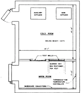
WARY ROOM
r"c"-T.1 rDI
-.. .
Fig. 1 Plan view
of cold room
COLD R W Y
C C I L I " I *,OH, - 10 r,.
I,'-,-
tion at any point in the cold room
is less than _t 0.1 F. Floor-to-ceil-
ing temperature gradients are less than 0.5 F. Air temperature can be controlled anywhere from -60
to 40 F on the cold side of a test wall.
For guarded hot box tests the warm room is heated by electric gravity baseboard convectors lo- cated along the wall opposite the test partition. The input voltage
to the convector is regulated by a
temperature controller. At t h e thermostat, air temperatures are controlled to k0.25 F. Air tem- perature gradients depend upon air circulation.
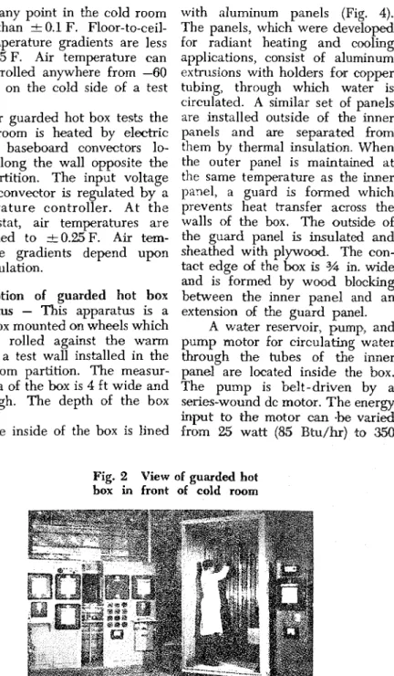
Description of guarded hot box
apparatus
-
This apparatus is alarge box mounted on wheels which can be rolled against the warm side of a test wall installed in the cold room partition. The measur- ing area of the box is 4 ft wide and 8 f t high. The depth of the box is 3 ft.
The inside of the box is lined
with aluminum panels (Fig. 4). The panels, which were developed for radiant heating and cooling applications, consist of aluminum extrusions with holders for copper tubing, through which water is circulated. A similar set of panels are installed outside of the inner panels and are separated from them by thermal insulation. When the outer panel is maintained at the same temperature as the inner
panel, a guard is formed which
prevents heat transfer across the walls of the box. The outside of
the guard panel is insulated and
sheathed with plywood. The con-
tact edge of the box is 34 in. -wide
and is formed by w d blm1cing
between the inner pznel and an extension of the guard panel.
A water reservoir, pump, and pump motor for circulating water
through the tubes of the inner
panel are located inside the box. The pump is belt-driven by a series-wound dc motor. T h e energ./
input t o the motor can
-be
variedfrom 25 watt (85 Btu/hr) to 3514
Fig. 2 View of guarded hot
watt (1200 Btu/hr) by regulating the voltage to the motor from 15 to 70 volt. The electrical input to the pump is normally sufficient to provide all of the wall transmis- sion; thus the energy i~nparted to the water by the pump serves to heat the panel ancl the energy loss from the motor and drive serves to heat the air directly.
Air heaters and water heaters are provided to supply an addi- tional 150 watt (500 Btu/hr) of energy and to vary the ratio of air heat to panel heat if so desired. T h e motor, pump, and air heaters which operate a t higher than panel temperature, are surroumtlcd by an additional set of panels through which water is circul;~tecl to pre- vent direct radiant exchange with the test wall surface.
A second reservoir and pump, located outside t h e box in the warm room, supply liquid (2/3 glycol
4-
1/3 water) t o the guard panel. The liquid is continuously cooled by
circulating part of it through a sec- tion of finned tubing mounted on the ceiling of the cold side. A hand valve regulates the flow of liquid t h o u g h the tubing. T h e reservoir contains an electric heater to con- trol the temperature of the Iiquit~.
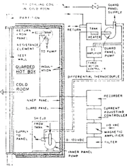
Instrumentation and control
-
The control system for the guarded hot box is shown in block form in Fig. 3. The d c input to the inner pancl pump motor and heaters is sup-pliecl by a 500-watt (100 volt and 5 amp) magnetic amplfier, the out- put pow(:r of which is regulated by a rcsistancc-element-tvne recorder J L
and current adjusting controller
The controller produces an output signal of 0 to 5 milliamp ancl by
manual switching all or part of the signal is applied to the control winding of the magnetic amplifier to regulate its output voltage from approximately 15.to 100 volt or 15 to 70 volt. This, together with re- sistance heaters which can b e con- nected in series with the pump motor, permits regulxtion of the maximum current to 5 amp and power regulation from 25 to 500
watt or 25 to 350 watt.
The rccorclcr has a 10 F span (65 to 75 F) and n sensitivity of 0.01 F o r 1)ettcr. Operating records ]lave shown that the inner panel tcrnperature is controllecl to within 0.01 F of set value.
The input voltage ancl current to the inner panel are measured 13y a millivolt recorder connected across appropriate resistors. The
Fig. 3 Schematic cross sec-
maximum recorder error, with cali- bration, is Limited to less than k 0 . 2 5 per cent of scale span so that by sizing the resistors to g h e larger than half-scale deflection this error is always less than 0.5 per cent.
A filter network on the outnut of the magnetic amplifier li&its ripple voltage to less than 0.75 volt. I t can be shown that the error due to the ac component is negligible for all power inputs. T h e total error in power measurement is less than 1 . 0 I ~ e r I cent.
A servo voltage multiplier is being procured so that input power can be recorded directly. This will
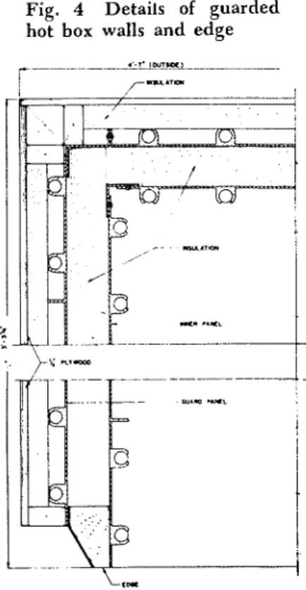
Fig. 4 Details of guarded hot box walls and edge
improve the accuracy of measure- ment and will facilitate the deter- mination of average power input. A differential thermocouple signal is a m p a e d and used to actuate a three-action controller to control guard panel temperature. The controller regulates an elec- tric heater. Heating can be sup- plied continuously on, continuously off or pulsed on-off by the con- troller. T h e sensitivity of t h e amplifier-controller arrangement is such that guard panel liquid tem- perature is controlled t o within t 0.05 F or less of inner panel liq- uid temperature a t the respective panel headers.
T h e rates of circulation are such that the temperature drops through the two panels are very small, less than 0.1 F. Also, the panel to water temperature dif- ference and the temperature varia- tion over the panel surface is less than 0.1 F. It is unlikely, there- fore, that the average temperature difference between the inner and guard panels exceeds 0.05 F.
T e m p e r a t u r e measurements are made with 30-gauge copper- constantan thermocouples and an electronic self-balancing tempera- ture indicator. With calibration of the apparatus, temperature differ- ence measurements are accurate to
t 0.2 F. This corresponds to an error of
+
0.67 per cent a t an over- all temperature difference of 30 F.Heat leakage
-
T h e r e are two sources of heat leakage in the guarded hot \,ox. Panel heat leak- age, leakage of heat between the guard a n d inner panels, is caused,by temperature differences between the two panels. Edge heat leakage is lateral heat flow at the junction of the hot box edge construction and test wall which results in an error in metered heat into the test area.
Panel heat leakage-The insul a t' ion
between the inner and guard pan-
els provides a calculated thermal
conductance of 0.18 Btu/hr/sq ft/ (F temperature difference) or a total heat flow of 19 Btu/hr/(F temperature difference). Tests were carried out on a wall of uniform
thermal conductance to determine
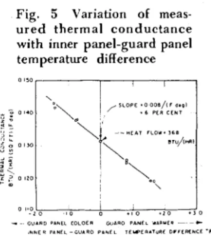
the actual panel heat leakage for a number of guard panel/inner panel temperature differences. The results are shown on Fig. 5. The variation in thermal conductance
of 6 per cent per F temperature
difference for the test wall denotes a panel heat leakage of 22 Btu/hr/ ( F temperahire difference). With the panel temperatures balanced
to i 0 . 0 5 F the actual panel heat
leakage is 1.1 Btu/hr as com-
pared with the estimated heat leak-
age of t 0.9 Btu/hr.
, r ition
Edge heat leakage-The p.1 t
framework in the cold room is constructed to nccommodate test walls 8 ft ligll with an allowance
of 1 in. for clearance a t the top
and the bottom. Movable vertical posts can be positioned for various test wall widths.
It is possible to install walls
from 4 to 13 ft in width. IVhich
width is prcfcrable depends upon thc thermal characteristics of the tcst wall and upon practic'il con- sidcrntions of wall fi1bric:ltion.
With walls having modules other
than 12, 16 or 24 in. for example,
it may b e desirable to have a test
wall wider than 4 ft and to make
tests a t more than one position, in order to determine the effect of joints or other discontinuities on the thermal coefficients.
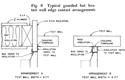
Fig. 6 shows the two edge ar-
rangements that have been used for guarded hot box tests to date. Arrangement A is used at the top a n d bottom of all test walls and a t the sides of test walls which are 4 ft wide. The test wall is sepa- rated from the surrounding parti- tion hy a l-in. thickness of rigid insulation. The wall is held in place in the partition b y compres- sion. All possiblc sources of mass transfer into or out of the box are sealed with either caulking coin- pound or tape. Arrangement B is
~ i s e d a t the vertical cdgcs of walls
wider than 4 ft. Strips of rigid in-
sulation 1 in. thick are caulked and
taped in place vertically on the test wall. In both arrangements the contact edge of the box is
Fig. 5 Variation of meas-
ured thermal conductance with inner panel-guard panel temperature difference 0 1 1 0 I - 2 [ 0 - 1 0 0 1 1 0 . 2 0 . 1 0 I I I
-
- G U A R D ' 1 U C l C O L O E I W l l O P A N E L W A l l Y T R - ~ - C I N N E R PnUEL - G V A R O ?..EL T E L P L R A T U I I E D V r l P f U C E - Fclamped against the protruding air temperature at the top edge is edge of the insulation. The box is about 2.5 F higher than that at the sealed to the edge of the insulation bottom edge, with a warm side/
with tape. cold side temperature difference of
whichever edge anangement 70 F. The air temperature gradi-
is Llsed, tile edge heat leakage ent in the warm room around the
error is a function of the average eclge of the guarded hot I)'" is
air temprature difrerence across similiar to that in the hot box.
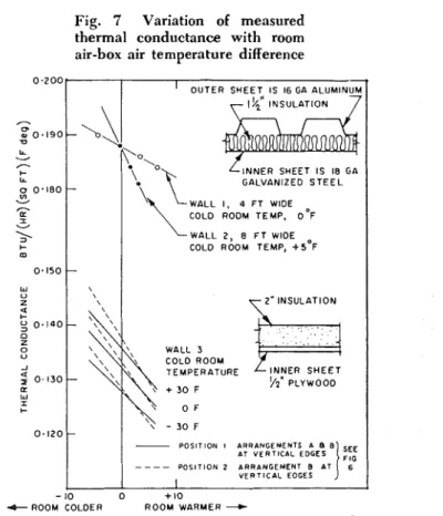
the edge. In Fig. 7 measured This is achieved despite the
thermal conductance is plotted confining effect of the hot box edge against warm room air/guarded construction hy providing gentle hot box air temperature difference forced circulation with a propellor for several test walls. The box air fan, which is directed to supple- temperature is the average air tern- ment the n;ituraI air motion in the perature 3 in. from the test w:ill warm room induced hy the 1)asc-
and the warn, room ;lir lmard convector on the wall oppo-
temperature is the average air tern- site the test specimen.
p e r a h r e surrounding the guarded ~ 1 1 test walls sl,c,w a
hot box edge, measured with thrr- measllred
mocouples. thermal conductance with air tem-
There is a vertical air tcm- perature diffcrencc between hot A
perature gradient in thc hot 1 ~ ) s box and warm room. T h e degree
dependent on the heat flow through of variation del3ends on test wall
the test wall. For walls of thermal constr~~ction and on thc ?pe of
conductance about 0.15 Btu/hr/sq edge arrangement that is used.
f t / ( F temperature difference), tlln \Valls 1 a n d 3 of Fig.
7
are almostFig. 6 Typical guarded hot box-
test wall edge contact arrangements
1 K 6 RIGID M S U I A T I O H
; :
ARRANGEMENT A TEST WALL WIDTH = 4 F T
- T E S T WALL RIGID I H S l L A T l O H CAULKING COMPOUND - I N S U L A T I O N TAPED I N S U L A T I O N ARRANGEMENT B T E S T WALL WIDTH > 4 F T
identical curtain walls. Wall 1 was 4 ft wide and edge arrangement A was used at the vertical edges. Wall 2 was 8 ft wide and edqe
arrangement R was used at the
vertical edges. The metal skin pro- vided a highly conductive heat transfer path across edge arrange-
ment B. Consequently, the lateral
heat transfer or edge heat leakage
across edge arrangement R was
greater than the lateral heat trans- fer across edge arrangement A for
a given air temperature difference.
Wall 3 of Fig. 7 is an 8- by
8-ft test wall of uniform thennal conductance. At position 1, edge arrangement A was used at one vertical edge and edge arrange-
ment B at the other. At position
2, edge arrangement B was used
at both vertical edges. The edge
heat leakage a t position 2 was
greater than the edge heat leakage a t position 1 for the same air tem- perature difference, since the re- sistance to lateral heat flow through the plywood surface in edge ar-
rangement B was less than through
the perimeter insulation in edge
Fig. 7 Variation of measured
thermal conductance with room air-box air temperature difference
0 . 2 0 0 '
I OUTER SHEET, IS 16 GA ALUMINUM
LL
-
/-.
+ LL INNER SHEET I S 18 G GALVANIZED S T E E L g 0 ' 1 8 0 - V-
I WALL 1 , 4 F T WlDECOLD ROOM TEMP, D'F
V m 0.150 W U z u 0 . 1 4 0 - 0 o U A a 0 I 3 0 W I + 0. I 2 0 -
C ROOM COLDER ROOM WARMER -+
ROOM A I R - B O X AIR T E M P E R A T U R E D I F F E R E N C E - O F - \ \ \ \ '\,\\, \ \\ \, \ ' \ \,
-
- WALL 2, 8 F T WlDECOLD ROOM TEMP, +5'F
2" INSULATION \ \ \, WALL 3 \ COLD ROOM \ + 3 0 F \ \ TEMPERATURE I/?' PLYWOOD \ O F \ \ - 3 0 F - P O S I T I O N I A R R A N G E M E N T S A 8 8 - - - - V E R T I C A L EOGES I 10 0 + 10
arrangement A. the surface temperature 5 in. from
With the warm room air tern- the edge was unaffected by the perature substantially higher than edge heat exchange. The distortion the box air temperature, the edge of the surface temperature pattern
heat leakage results in a d e c r e a x from this point to the edge at
in metered heat flow into the test equal warm room and hot box area and vice versa. It would be temperatures was quite small, ex-
desirable if there were no lateral cept at the junction of the speci-
heat flow at the edges of the test men and perimeter insulation; edge
section with hot box and warm heat leakage resulted in a n increase
room at the same temperature. The in heat flow at the inner surface
surface temperature Pattern at the in both edge arrangements. Similar edge would then be unaffected by measurements indicated a corn-
the Presence of the box and con- parable increase in heat flow at the
ditions would be ideal for measur- top edge and perhaps a small de-
ing a correct value of thermal con- crease in heat flow at the b t t o m
ductance. edge with equal average warm
Fig, room and hot box air temperatures.
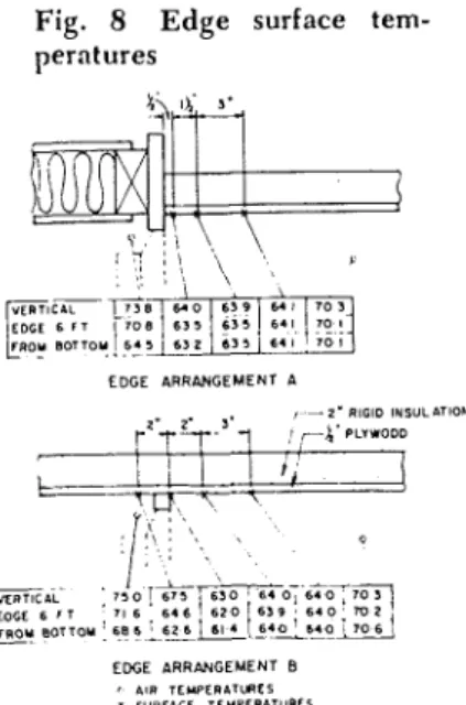
tures measured a t the vertical edges To assess the error due to edge
of wall 3 with different warm room heat leakage a relaxation calcula-
air temperatures for both edge ar- tion2 was carried out for a homo-
rangements A and B. A t
geneous wall with edge arrange-
values of hot box/wam room air merit A. section studied is
temperature difference to F, shown in Fig. 9 a,ong with the
t e m p ~ r a t u r e distribution obtained. The calculation has been made for
Fig. 8 Edge surface tern- equal air temperature in warm
perntures room and hot box and equal sur-
face conductances. This latter as- sumption can be shown to be rea- sonably valid for the air and sur- face temperature conditions shown
for edge arrangement B in Fig. 8
and therefore also for edge ar- rangement A. I t has also been assumed that the surface of the
EDGE A R R ~ N G E M E N T A edge insulation in contact with the
r - z . R I G I D IHSULIlTlOH
r2-T% 3J'7 , pLywoDD hot ~ H ) X is at hot box temperature.
I I
t
-
I x 1 ,i
There is distortion of the iso-therms a t the edge of the specimen primarily as a result of two factors.
EAL 7 3 0 ~*-4-07 6 f o T ~ First, the temperature gradient in
LOGE 6 r T 71 6 6 4 6 1 6 1 0 6 3 9 6 4 0 X I 2
bu
BOTTOY 6 8 6_
6 2 6 6 l 41
6 4 0 ! 5.0; 1 0 61
the adjacent construction is differ-E W E A R R ~ G E M E N T B ent from that in the specimen
r r \ l n TLYPERATLRES
thermal resistance of the former. Consequently, all p i n t s through the depth of the specimen tend to h e at a slightly higher temperature at the edge than at similar loca- tions removed from the edge with a resulting tendency for lateral heat flow into the test section. Counteracting this is the effect of the projection of the edge insula- tion on the warm side which tends to lower temneratures at the ad- jacent inner s'urface of the speci-
men. T h e net effect is a small in-
crease in metered heat flow from the hot box into the test area of the spe~imen.
The increased heat flow at the ctlge of the specimen for arrange-
~ n e n t A, as determined from the
assumed inside surface conduct- ance and the calculated surface
temptratures in Fig. 9 represents
0.3 per cent of the total heat flow
into the test area. p n the other hand, the heat floy from the hot
11ox into the edge,insulation is 2.7
per cent of the tfial heat flow into the test area. The calculation thus
indicates that with the hot box
and the warm room air tempera- tures balanced, the error in meas- ured thermal conductance due to
edge heat leakage is
+
3 per cent.This is confirmed by the calculated value of thermal conductance f m the test wall, based on measured
values of conductivity for the insu-
lation and published values of thermal conductance for plywood,
which is 3 to 4 per cent lower than
the value obtained in the guarded hot
h x .
N o rel'isation calculation has heen made of the eclge heat leak- age error for edge arrangcment 13. T h e isotherm pattern, which can
he visualized hy reference to that
for arrangement A in Fig. 9, will be affected only by the l-in. square strip of edge insulation and will be symmetrical about it. The dis- tortion of the isotherms at the inner surface of the specimen ad- jacent to the edge will be similar
to that in Fig. 9 but slightly more
pronounced, since there will not be the counteracting effect of the
thicker edge construction. Thus. < 2
for thin walls at least, the error due to edge heat leakage with warm room and hot box air temperatures 1,alanced is likely to b e slightly greater. This is confirmed by the
results in Fig. 7, which for wall 3
shows slightly higher values of thermal conductance at balance
with arrangement
-
B at both verti-cal edges.
The error due to edge heat leakage can he minimized by rv- ducing the projection of the edge insulation from the inner surface of thc test specimen. Ideally, this shoultl approximate the inside sur- face cvnductance of the spPcimen,
which would
be
achieved withabout 54 -in. thickness. T h e project-
ing insulation acts as a gxsket to
overcome irregularities in t h e c 7
planencss of the wall specimen.
T h c l-in. proj(>ction w a chosen to
facilitate. s c ; i l i n ~ 0 of the box with
t a m . Altcmative methtds of seal-
ing the 1)ox to the spt~imc,n \vhich
will permit ;i smaller projection of
the edge insulation arc being con-
sidcrtd. This is c ~ s r x ~ t c ~ d to rcducc
errors diic to edge licat Icakagc. to negligi1,le proportions ;it cclual hot
hos and warm room air tcn11x.r:l- I
turcs. Flirthcr invc.stigations of
trlgcb brat Icakagc arc plannctl
rt.l;itive to tllc cffcvt of diffvrcnt
surface conductances a n d air tem- peratures with various wall con- structions and edge arrangements.
It is thought that the resistance "
paper analog might be adapted for this study. I t will b e recognized that edge heat leakage is equally a problem with the traditional guarded hot box."
WARM SURFACE HEAT
EXCHANGE
H e a t t r a n s f e r c h a r a c t e r i s t i c s of wall c o n s t r u c t i o n s usually a r e specified 01.
compared on the basis of t h e thermal t r a n s m i t t a n c e coefficients o r U values, which include t h e s u r f a c e conduct- ances. S i n c e the s u r f a c e conductance is a function of s u r r o u n d i n g condi- tions, i t i s necessary t o u s e s t a n d a r d values. I n the A S H R A E G U I D E in- s i d e s u r f a c e conductances a r e based on natul,al convection, w i t h a i r ant1 s u r r o u n d i n g s a t t h e s a m e tempera- ture. I n t h e traditional guarded hot box, forced convection is proritieti, so t h a t t h e inside s u r f a c e conductances a r e u s u a l l y much h i g h e r than those f o r n a t u r a l convection. I t is neces- s a r y , t h e r e f o r e , t o base t h e thermal conductance of t h e wall o n measured s u r f a c e tem[!eratures a n d t o compute t h e U v a l u e , in corpora tin^ the stantl- a r d inside surface conductance.
T h e inside surface t e m p e r a t u r e dis- tribution a n d t h e r e f o r e t h e t h e r m a l conductance of n o n - u n i f o r m walls i s affected by the inside s u r f a c e conduct- ance. T h u s the t h e r m a l conductance obtained w i t h forced convection on t h e inside m a y differ s o m e w h a t from t h a t f o r n a t u r a l convection. F u r t h r r m o r e . i t i s s o m e t i m e s dificult to establish a n a p p r o p r i a t e a v e r a g e surface-to-sur- f a c e t e m p e r a t u r e difference by direct m e a s u r e m e n t f o r t h e determin;ition of t h e r m a l conductance of non-unifomm walls because of t h e variations in s u r - f a c e t e m p e r a t u r e .
I t is therefore d e s i r a t ~ l e in h e a t flow m e a s u r e m e n t s t o provide surfrtccl conductances closely a p p r o x i m a t i n s s t a n d a r d \.slues used f o r c;~lculatinr:
U values a n d to k n o w t h e surf;ice h e a t c s c h a n g e characteristics of the al)- p a r a t u s ~ ~ r e c i s c ~ l y , in o r d e r to facili- t a t e t h c tieteimination of t h e r m a l conduckinc.e.
The total h e a t exchange between a
t e s t wall surface and the guarded hot box is t h e sum of the convection ex- change between the surface a n d the box a i r and the radiation exchange between the surface and t h e box inner panel surface.
qt = qr
f
qc (1)In a grey enclosure, such a s the guarded hot box, the radiation ex- change' is:
qr F,,
,
(Tt - T x 4 ) (2)F o r one source (guarded hot box) and one sink surface (test wall) and no interconnecting surfaces, it can be shown t h a t
1
The radiation component can also be accounted f o r by the following:
q r = h r (t,-t,)
where ( 4 )
guarded hot box tests, the error in using equation (6) is less than 0.05 per cent.
The h e a t transfer between the a i r in the guarded hot box and test wall surface i s by natural convection. T h e convective movements are brought about solely by differences of density caused b y differences of temperature. Natural convection can be expressed in dimensionless terms by relating the Nusselt, Grashof and Prandtl numbers a s follows'
Nu = x (Gr P r ) '
T h e constants x and y a r e evaluated from experimental d a t a . The equa- tion can be applied to all tests in t h e guarded hot box provided t h a t t h e
(T: - T W 4 ) geometry of the system remains t h e
h , = F , , o (5) same and (Gr P r ) lies within t h e
(TP-Tw) range of conditions used in the orig- inal evaluation of the constants.
Equation ( 5 ) can be approximated by The bulk temperature of the fluid,
the following: well a w a y from t h e surface, is used in
h, = 4 F,, a (T,)' t h e determination of t h e temperature
(6) difference (t.
-
t,). T h e values ofF o r the range of conditions in the the physical constants C,, p, k, and P
Fig. 10 H e a t exchange i n guarded hot box by natural convection
I
: I l l ! ;rr 4 1 8 F T WALL
a r e taken a t the arithmetic mean tem- perature of surface and bulk fluid. The height of t h e wall surface is taken a s the characteristic linear dimension, L.
Because the temperature range in the guarded hot box tests i s small, the physical properties of a i r may .be regarded a s constants. Equation (7 j can therefore be simplified to:
h. = x' (t. - t,-)" (8) where
The heat flow r a t e due to convec- tion is:
q c = h, (t. - t,,) (10) The total heat flow rate f r o m equa- tions ( I ) , (4) and (10) is
Combining h, and h, to form the usual surface conductance f~ and defining a n equivalent temperature t ~ , equation
(11) becomes:
q1 = f , (tl - t , ) (12) The equivalent temperature, tl, is t h e temperature of a i r and panel surface which would produce the same total heat flow r a t e a s t, and t, and is cal- culated f r o m equations (11) and (12)'.
hr t,
+
hc t,t l = ( 1 3 )
hr
+
h,F o r a test on a wall of uniform con- ductance where it is possible to meas-
ure the average surface tempel-ature, t,., accurately, q, can be readily cal- culated from equation ( 2 ) . knowing the emissivities and interchange fac- tor. Since q, is accurately measured, q, and hence I?, can be determined from equations ( 1 ) and (10). A num- ber of values of h, can be obtained from tests a t a number of different total heat flow rates. The dimen- sionless groups from equation ( 7 ) can then be evaluated f o r each of the tests and the constants x and y de- termined by correlation.
The following three series of tests were carried out with the guarded hot
box to evaluate t h e convection con- stants:
1. Tests a t different total heat flow rates on a uniform 4- b y 8-ft wall painted flat white (e, = e, = 0.87) 2. Tests a t different total heat flow
rates on same wall a s above but covered with aluminum foil (e, = 0.87, e, = 0.05)
3. Tests a t different total heat flow rates on a uniform 8- b y 8-ft wall painted flat white (e, = e, = 0.87) The total hemispherical emissivities quoted w e r e estimated f r o m the meas- ured-otal normal emissivities. F o r this purpose the total hemispherical emissivity was taken a s 0.95 and 1.15 of the total normal emissivity for non- conductive and conductive surfaces, re- spectively'. The over-all interchange factors w e r e calculated f r o m equation (3). F o r all tests A, = 32 sq f t , A, = 137 sq f t for series 1 and 2 a n d 153 sq f t f o r series 3. T h e change i n box surface area w a s due t o extensive modifications carried o u t between series 2 a n d 3 tests. Average a i r a n d surface temperatures w e r e measured with thermocouples. The temperature of the inner panel circu!ating fluid was taken a s the average tempera- t u r e of t h e inner surface of the guard-
ed hot box. All a i r properties were
taken f r o m reference 8.
The t e s t results a r e shown plotttd i n Fig. 10. Curves f r o m Fishenden and Saunders also a r e given. There is substantial disagreement betweer: the results f o r the high a n d low emis- sivity surfaces. F o r t!lis reason t?le results f o r each were correlated sepa- rately by t h e method of l e a s t squares. The analysis indicated t h a t convec- tion to t h e test wall surfaces may be represented by t h e following equa- tions:
F o r e,
=
e, = 0.87 F o r e, = 0.05, e,-
0.87Nu = 0.42 (Gr Pr)'.= (15) Considering air properties as belng constant t h e equations c a n be simpli- fied to t h e form of equation (8) as
follows:
F o r e, = e, = 0.87
The difference in the r a t e of convec- tion heat exchange for t h e high and low emissivity surfaces can be ex- plained by reference to t h e various heat exchanges taking place in the
guarded hot box, shown in Fig. 11.
A summation of the h e a t exchanges gives:
hence
Test results show t h a t t h e panel sur- face t o a i r temperature difference
(t, - t.) is quite small. Furthermore,
a t equal a i r to wall surface tempera-
ture difference ( t - t,), the differ-
ence between (b - t ) f o r t h e high
and low emissivity wall surface is negligible. I t can be seen from equa- tion (19), therefore, t h a t the differ- ence in the convection exchange, q,, a t equal values of (Gr P r ) f o r t h e high and low emissivity wall surfaces is
due to differences in the motor loss ql.
Since t h e motor loss increases with increasing total heat input, q, In- creases proportionately. The increased radiation exchange to t h e high emis- sivity surface requires a larger total heat input. The convection heat rate, q,, is therefore larger f o r the high emissivity surface.
The equation to be used f o r t h e cal- culation of t h e convective component of the surface conductance therefore depends upon test wall emissivity. The two equations determined here correspond to t h e extremes of surface emissivity likely to be encountered in guarded hot box tests.
The convection equations compare
favorably with the recommended
equation f o r turbulent flow on vertical free plates (curve A Fig. 10). This is expected since turbulence is known to set in a t ( G r P r ) about 10' although a t values of 1 0 9 0 10" it is still fully developed only a t the upper p a r t s of the surface. I t is thought t h a t the over-all effect of the boundaries is to reduce the convection h e a t transfer below t h a t expected on a f r e e plate of the same dimensions. This is offset, however, by t h e presence of the pump motor, which increases t h e convection heat transfer by increasing circula- tion.
Equations ( 6 ) , (16) and (17) are
used in calculating surface contluct- ances f o r guarded hot box tests.
Where t h e wall surface emissivity falls between values f o r which t h e convection equations a r e valid, t h e surface can usually be painted t o provide a n emissivity approximately
equal to 0.87. These equations c a n
also be used to determine an average surface temperature f o r non-uniform walls from which a wall thermal con-
ductance can be calculated. Rear-
ranging equation (11) gives
from which t, can be obtained b y trial and error.
The surface conductances provided in the hot box tests compare favor- ably with those recommended by t h e
ASHRAE G U I D E D f o r purposes of
computation. F o r a surface of emis-
sivity 0.90 and temperature 70 F fat-
ing surroundings having a n emissivity of 0.90 and a t t h e same temperature
a s the ambient air, the GUIDE recom-
mends a combined surface conduct- ance of 1.46 based on a surface-air
temperature difference of 10 F. F o r
t h e s a m e conditions t h e surface con- ductance with t h e guarded hot box is 1.45.
Fig. 11 H e a t exchange in
guarded hot box
TEST WALL
COLD SURFACE HEAT transmittance coefficient for such
EXCHANGE walls is therefore between
+
0.2,Forced convection is provided in the per cent and
+
5.8 per cent. Alter-cold room by a i r movement inducetl native of sealing the box
by the diffuser fans. Each f a n motor
h a s three s p e d settings and the total to the wall specimen which will
a i r discharge r a t e can be varied fronl largely eliminate edge heat leak-
2800 to 11,400 cfm in six steps. The
discharge r a t e decreases slightly with error are being considered.
f r o s t build-up on t h e evaporator coils. T h e total percentage error will de-
Tests on smooth-surface uniform crease as the temperature difference
walls with emissivity equal t o 0.9
have shown t h a t outside surface con- between hot and
ductance, f,, varies between 3 a n d 4 increases or as the thermal con-
with the main diffuser f a n operating ductance of the wall increases.
a t high speed.
The variation in surface conduct- The error in measuring ther-
ance with h e a t flow, temperature level mal conductance depends on the
and wall emissivity is r a t h e r small reliability with which an appro-
since the heat transfer is mainly by
forced convection. Calculations f o r a P i a t e average surface temperature
typical wall show that t h e radiant can be measured or estimated.
component of t h e surface h e a t ex- Operation indicates that heat trans-
change may vary from 0.4 to 0.75 f o r
a wall of 0.9 emissivity and from 0.1 m i ~ ~ i 0 n coefficients Can be repro-
t o 0.2 f o r a wall of 0.25 emissivity a s duced within 1.0 per cent.
t h e cold room temperature varies from The temperature of the inside
- 4 0 to 40 F.
surface of the hot box is under
CONCLUSION
It has been shown that heat flo\v
through any 4- by 8-ft section of
test walls up to 12, ft in length can
b e metered reliably with the guarded hot-box cold -room ar- rangement described in this paper. The total error in determination of thermal transmittance coefficients depends upon test conditions and on wall thermal conductance. For
a wall of U value 0.1 Btu/hr/sq ft/
F at a temperature difference of
30 F the total of panel heat leak- age, control a n d measurement
errors, if additive, is
+
2.8 per cent.The edge heat leakage error de-
pends upon wall construction and edge arrangement. For thin wall sections with the edge configura- tion used to date it is about + D per cent.
The error in measured thermal
direct control. This makes it pos- sible to operate the box under con- ditions of natural convection with- out excessive vertical air tempera- ture gradients and to exercise some control over the relationship be- tween box surface a n d air tem-
perature. With energy supplied
only to the pump motor the air temperature has been generally
within ?h F of the box surface tem-
perature in tests on typical walls. Relationships describing the radiant and convective components of the inside surface conductance, applicable to most walls, have been determined for the box. These relationships can also b e used to determine an average inside sur- face temperature for non-uniform walls from which a wall thermal conductance can b e calculated. T h e inside surface conductances provided 1)y the box a r e similar to
those that occur in practice under natural convection conditions. Real- istic outside surface conductances can b e provided in the cold room.
ACKNOWLEDGMENTS
The authors wish to thank Dr. D. G. Stephenson f o r his advice in connec- tion with the relaxation calculation. The contributions of Dr. N. B. Hutch- eon, Assistant Director of t h e Div of Building Research, in the planning of the facility a r e gratefully acknowl-
edged. This is a contribution from
the Div of Building Research, Na- tional Research Council, Canada, and i s published with the approval of the Director of the Div.
NOMENCLATURE
A = area of a surface, sq f t
A,,, inside surface of guarded hot box
.4,, surface of test wall
C
=
thermal conductance, Btu per( h r ) ( s q f t ) ( F temp diff) C,= specific heat of a i r a t con-
s t a n t pressure, Btu p e r (Ib) ( F )
e = total hemispherical emissiv-
ity of a surface, dimension- less e,, inside surface of guarded hot box
e , ~ , surface of test wall
f = combined surface film con-
ductance, Btu p e r ( h r ) (sq f t ) ( F temp diff)
f , , warm surface; f,, cold surface
F., = over-all interchange factor
f o r radiation from test wall to guarded hot box, dimen- sionless
g = local acceleration of gravity,
f t per (sec')
Gr = Grashof number, /3 g p' L'
(t.
-
t,)/p2, dimensionlessh = surface conductance, B t u per
( h r ) ( s q f t ) ( F temp diff) h... convection; h,, radiation
k = thermal conductivity of air,
I3tu per ( h r ) (sq f t ) ( F pcr f t of thickness)
K = thermal conductivity, Btu p e r
( h r ) (sq Tt) ( F per in. of thickness)
L = characteristic linear dimen-
sion for convection, f t
Nu = Nusselt number, h, L/k, di-
mensionless
P r = Prandtl number, p C,/k, di-
mensionless
q = heat flow rate, Btu per ( h r )
(sq f t )
q,, convection heat exchange between box air and t e s t wall surface
q',, convection h e a t exchange between box inner panel surface and box a i r
q ~ , convection heat exchange
between box motor a n d box a i r
q,, radiation h e a t exchange between box inner panel surface and test wall s u r - face
q,, total heat exchange be- tween box and test wall, also equal t o total heat input to box
T = absolute temperature, X
(deg)
T., average a i r temperature in guarded hot box T,, average temperature of
inner panel surface of guarded hot box
T,, average temperature of test wall surface
T,, mean temperature be-
tween inner panel surface and test wall surface
t
-
temperature, F (deg)t., average a i r temperature in guarded hot box t , , temperature equivalent tu
t, and t.
t,., average a i r temperature in cold room
t,, average temperature of inner panel surface of guarded hot box
t., , average temperature of
test wall surface
U = thermal transmittance, Btu
per ( h r ) (sq f t ) ( F tern11 diff)
Greek L e t t e r s p
-
coefficient of t h e r m a l e x p a n - sion of a i r , l/T, p e r R a = Stefan-Boltzmann c o n s t a n t 0.1712 X 10.' B t u p e r ( h r ) ( s q f t ) ( R ) ' p = d y n a m i c viscosity of a i r , Ib p e r ( h r ) ( f t ) p = m a s s d e n s i t y of a i r , s l u g s p e r ( f t ) ' BIBLIOGRAPHY' L t ~ r p e - S c x l e Wall Heat-Flow M e a s u r i n g AD- ptlmtus. I(. R. Solvason. ( A S H H A E T r a n s a c - tions. Val. 65. 1969. p. 5.11-560).
Relaxation Methods, D. Allan. (McGra\v-Hill, New York. 1954).
' Method of T e s t for T h e r m a l Conductance ant1 T r a n s n i i t t a n c ~ nf Built-url S e c t i o n s 1.y Means oE t h e Guarded H o t Box. ASTM Designation C236-
K A T
' H e a t Transmission. W. H . McAdams. (Mc- Graw-Hill. N e w York. 1 9 5 4 . 1,. 7 2 ) .
6 H e a t T r a n s f e r , M. ?ishenden and 0. A. Saunders. (Oxford U n ~ v e r s i t y P r e s s . London, 1950, D. 8 9 ) .
' Method of T e s t f o r N o r m a l T o t a l E m i t t a n c e >f S u r f a c e s of Materials 0.01 in. or less i n rhickness a t Approximately Room T e r n ~ ~ r i ~ t u r e . ASTM Designation C415-59T.
' M e a s u r e m e n t of A n g u l a r Emissivity, A . U m u r , G. V. Parrnelee a n d L. F. S c h u t r u m ( A S H A E T r a n s a c t i o n s . Val. 61. 1955, D. 111).
8 Tables of T h e r m a l P r o n e r t i e s of (;aspa (Na- tional B u r e a u of S t a n d a r d s , C ~ r ~ u l a r 561; 1955). O A S H R A E GUIDE. 1960, D. 108.