Publisher’s version / Version de l'éditeur:
Vous avez des questions? Nous pouvons vous aider. Pour communiquer directement avec un auteur, consultez la
première page de la revue dans laquelle son article a été publié afin de trouver ses coordonnées. Si vous n’arrivez pas à les repérer, communiquez avec nous à [email protected].
Questions? Contact the NRC Publications Archive team at
[email protected]. If you wish to email the authors directly, please see the first page of the publication for their contact information.
https://publications-cnrc.canada.ca/fra/droits
L’accès à ce site Web et l’utilisation de son contenu sont assujettis aux conditions présentées dans le site
LISEZ CES CONDITIONS ATTENTIVEMENT AVANT D’UTILISER CE SITE WEB.
Report (National Research Council of Canada. Division of Building Research); no. DBR-R-77, 1955-12-01
READ THESE TERMS AND CONDITIONS CAREFULLY BEFORE USING THIS WEBSITE.
https://nrc-publications.canada.ca/eng/copyright
NRC Publications Archive Record / Notice des Archives des publications du CNRC :
https://nrc-publications.canada.ca/eng/view/object/?id=d8b6be11-a4c7-4501-9a26-e84a06bbb988 https://publications-cnrc.canada.ca/fra/voir/objet/?id=d8b6be11-a4c7-4501-9a26-e84a06bbb988
Access and use of this website and the material on it are subject to the Terms and Conditions set forth at
Structural Testing of Two W-Trusses
DIVISION OF BUILDING RESEARCH
STRUCTURAL TESTING OF TWO W-TRUSSES by
D.B. Dorey
(A 」ッセッー・イ。エゥカ・ project with the Forest Products
Laboratories, Department of Northern Affairs and National Resources, Ottawa)
Report No.
77
of the
Division of Building Research
Ottawa DC(;c:iliJer QYUセ
Development of economies in house design and construction is a continuing responsibility of the Division of Building Research. In such studies the Division has been considering
critically each of the principal components of the standard house with a view to improvement in design and economy.
This has led to an investigation of roof design in which the Division has followed the lead of American research
workers in considering the possible use of prefabricated trusses for house roofs in place of the conventional built-in roof design.
This report describes the first experimental work carried out by the Division in this field, utilizing a design
developed in the United States, but subject to the more severe loadings which have to be anticipated in Canada.
The work described is only a beginning, but it did give useful information and provided good experience in experi-mental techniques which can be applied in further work in this field which has already been started. The research work herein described has opened up several useful avenues of
inquiry, the first results of which the Division hopes to be able to publish in
1956.
In all its work in which wood is involved as a material, the Division has the ーャ・。ウセゥセ and privilege of working closely with the Forest Products Laboratory of the Department of
Northern Affairs and National Resources of which Colonel J.H. Jenkins is Chief. Although the Division of Building Research accepts full responsibility for the work herein described, it was carried out in close consultation with the Forest Products Laboratories, and it is for this reason that this liaison is indicated on its title page.
The author, D.B. Dorey, is an Assistant Research Officer and was a member of the Building Design Section (W.R. Schriever, Head) when the work described herein was done. Mr. Dorey is now Officer in Charge of the Atlantic Regional Station of the Division at Halifax.
R.F. Legget Director. Ottawa
Home builders in Canada are always on the alert for new developments which will facilitate their activities and
improve the quality of their finished products. Among more recent developments, the trussed roof is receiving consider-able attention as an alternative to the conventional rafter systems. This attention is largely due to the advantages which trusses offer to a builder when the economics of his operations justify the following:
(i)
(ii)
(iii)
Precutting and pre-assembling of house components at a convenient location (a) when shop facilities are available and (b) when there is a shortage of skilled workmen to do on-site cutting and framing; Speed of erection, such as (a) when seasonal weather hampers continuous work or (b) when specialized
crews move from house to house doing one operation; Clear spans fur flexible interior layout.
Trussed roof 」セョウエイオ」エゥッョ for dwellings in Canada has been influenced ァイセ。エャケ by the work of research organizations in the United States. Notable among these organizations has been the Small Homes Council of the University of Illinois. The Small Homes Council has pUblished several working sheets of data on house trusses which can be readily used by home builders to mention only one example of the useful information that has been made available. A review has been made of this information to assist in similar work at the Building Research Centre. In, this work the more severe loading conditions
imposed by the Canadian climate are taken into account. 2. DESIGN OF TVlO W-TRUSSES
To acquaint home builders attending the Conference on Building Research
(1953),
and also those attending Open House activities(1954),
with the features of house truss design, a full-scale model of an end section of a house was erected in the large project area of the Building Research Centre.This model consisted of two 8-foot sections for side walls, end wall, and three w-trusses having a 6 in 12 slope. The trusses were designed according to the recommendations
of the
1953
edition of the National Building Code of Canada. Two trusses were of identical construction; the third truss differed from the first two in the construction of the lowerchord members. The upper chords were fabricated from 2- by 8-inch stock and the remaining members were made from 2- by 4-inch, except for the third truss which had a lower chord made from 2- by 6-inch stock. All the stock used was air-dried No.1 Eastern Spruce. Joints in all three trusses were made by 2!-inch split ring connectors and! inch diameter bolts. The details of the two identical trusses which will be dealt with later are shown in Fig. 1.
It was found that, although it would be desirable to use 2- by 6-inch material with a lap joint at the uppermost panel point, 2- by 6-inch stock would be overstressed in the upper chords. The size of the upper chords, therefore, had to be increased, and since lumber is uEually manufactured in even widths, a 2- by 8-inch nominal section was selected. This obviated a departure from the design used by the Small Homes Council because of the limited strength of a lapped joint at the top panel point. To overcome this difficulty, and to improve the strength of the top joint sufficiently, the 2-by 8-inch upper chord members were given a common rafter cut and were butted together. It was also found necessary to change the design of the lower chords because of the increase in the design loadings over those used by the Small Homes Council. Imposed forces in rhe lower chords required the use of two nominal 2- by 4-inch members to connect the heel joints to third points of the lower chords,
When the useful purpose uf the display house model was at an end, it was disassembled and the two identical trusses were retained for structural testing.
3.
TESTING OF W-TRUSSES (a) Purpose of TestSince this test was the first of this type to be carried out by the Division, it was important to learn as much as
possible about the necessary testing technique. The objectives of the test were therefore as follows:
(i)
(ii)
To study the performance of two W-trusses designed according to the National Building Code (1953), when subjected to loads up to failure; and
To study a proposed method of testing as a means of testing similar house components in the large project area.
(b) Preparing Test Assembly
As opposed to testing each truss separately, the two trusses were mounted side by side on supports having the approximate lateral stability of one-storey house walls. The spacing on the supports was set at the design spacing of 24 inches on centres. The upper chords were joined together with 4-foot lengths of sheathing boards to provide the
required tributary roof area for loading and also to simulate the working conditions of trusses in a house roof as nearly as possible. Furring strips were nailed to the lower chords in a manner duplicating the furring arrangement in the
ceiling of a house. To prevent sidesway and possible over-turning of the test assembly when loaded, a stabilizing framework was anchored to the floor beams of the project laboratory.
Each panel point of both trusses was assigned a reference letter and a system of wires and pulleys was installed to
record vertical and horizontal movements at the panel points on W-truss No. II. A deflection board was securely anchored to the floor of the project laboratory and each deflection wire was appropriately referenced and tensioned by a standard reference weight. Figure 2 shows the test assembly with the ceiling load and the eqUivalent dead load of the shingles in place on the trusses.
(c) Method of Loading and of Recording Deflections Standard 1-, 10-, and 20-lb. lead-filled bags were uniformly distributed on the tributary roof area and on the furring strips of the lower chords to simulate one times the design load plus dead load. Since the number of lead-filled bags was limited, loads in excess of one times the design live load for symmetrical loading were superimposed by applying pea-sized crushed stone. The crushed stone was confined to the tributary roof area by specially constructed bulkheads.
Figure 2a shows the test assembly with the bulkheads in position. Deflections, both horizontal and vertical, were measured at each panel point on W-truss No. II by a system of wires running over small pulleys. Dial gauges were also used to read deflections on the lower chords of each truss but were removed when twice the design live load was reached. The system of wires and pUlleys provided a continuous record of the deformed shape of W-truss No. II; the dial gauges provided a record of the initial deflections in the lower chords and served as a check on the wire and pulley system. In addition to the mechanical methods used for measuring deflections, the Photogrammetry Section of the Division of Physics measured
deformltions by a photogrammetric method. The latter method is エィセ subject of a separate report.
(d) Testing Procedure
The sequence followed in applying the loads was as outlined in Tahle I. The ceiling load of 10 lb. per square foot and the ,dditional dead load of 210 lb. per square (10 by 10 feet) for asphalt shingles were applied to the trusses. This loading remained in place for the duration of all
loading phases. Deflection readings were taken each day for twenty days before any live loads were added. This period was allowed in order to give sufficient time for the trusses
to "bed down" at the joints and supports. Since the records show a pattern of uniform deflections on the lower chords for the 20-day period, only those deflections taken at five-day intervals are given in Table II.
At the end of the 20-day period of the first loading phase, the N.B.C. design snow loading of
50.8
lb. per square foot of the horizontally projected roof area was applied inincrements of one-half the design live load and was allowed to remain on the trusses for a period of seven days. The lead-filled bags were applied manually and simultaneously to both roof slopes from a platform erected beside the test asseffibly. Deflection records were made from both the dial gauge readings and the deflection board. The dial gauge readings have been reduced in Table III to show the net deflections at the lower chord panel points with respect to the end panel points. Figure
3
shows the trusses loadedwith the design live load plus dead loading and ceiling load. When the seven days for the second loading phase had elapsed, the design live load was removed and twenty-four hours were allowed for the trusses to recover before further loading proceeded. The net deflections and the residual settlements at the supports are alsolgiven in Table III for immediately after the removal of the design live load and 24 hours later. Moisture content readings for the truss members taken daily showed that the moisture in the wood remained at approximately
7
per cent.For the third loading phase, the design live load was re-applied and allowed to remain for a period of 24 hours. This loading phase was designed to serve as a check on the ability of the trusses to give repeated deflection readings for the same magnitude of loading. After 24 hours, the load was removed and an additional 24 hours were allowed for
recovery of deflections. The deflections for the period under load and after the recovery period are given in Table IV.
The fourth and fifth loading phases were designed to produce the effect of a bUild-up of snow on one slope while the opposite slope remained bare. To approximate this
arbitrary loading condition,
1.33
times the design live load (snow load) was applied, first to one slope with no live load on the opposite slope and then to the other for the reverse condition. For each of these loading phases, the loads were left in place for 24 hours and a minimum of 24 hours was allowed for recovery of deflections. The deflectionsresulting from these unsymmetrical loading phases are given in Table V for the sustained loading period and for the
recovery period. The moisture content of the members in the trusses remained at apprOXimately
7
per cent.Since the available supply of lead-filled bags was limited, and not sufficient to carry the test to failure, the test assembly had to be altered to accommodate crushed stone before the sixth loading phase could be carried out. Sideboards and bulkheads were made up and mounted parallel with the roof slopes on the stabiliZing framework in such a way as to form a bin around the tributary roof area. The approximate capacity of this bin in terms of crushed stone was equivalent to four times the design live load plus dead
load. The total depth of the sideboards and bulkheads to give this capacity was 28 inches,
4
inches of which extended below the roof sheathing boards to allow for deflections whichwould take place under loading. Clearance to the extent of
t
inch was allowed around the edges of the roof sheathing boards so that the trusses could deflect when loaded without being restrained by the surrounding framework. Adjustable tie rods were put through the sideboards to prevent them from spreading under the outward thrust of the crushed stone. All joints in the framework were secured and crossbeams were put through under the upper chords of the trusses and bolted to the stabiliZing framework in order to prevent abrupt and complete collapse of the assembly. A space of approximately4
inches was allowed between the upper chords of the trusses and the crossbeams ror the trusses to deflect before failure.To transfer the crushed stone from the stockpile on the floor セヲ the project area to the tributary area of the trusses, a special bucket was designed which could be dumped from the floor with a small rope while suspended from the overhead
crane. The capacity of this bucket was approximately two
cubic feet of pea-sized crushed stone. To maintain an accurate record of the material being placed on the trusses, a set of platform scales was provided for weighing of each bucketful of crushed stone.
During the sixth and final loading phase a minimum of five men were reqUired. Two men were required to fill and weigh the bucket, one to operate the overhead crane, one to
dump the bucket, and one to spread the crushed stone uniformly on the tributary roof area.
The crushed stone was applied to the test assembly in increments of one-half the design live load until failure occurred. Deflections were recorded at the end of each loading increment and regular inspections were made of the two trusses. When four times design live load was reached, the supply of crushed stone was exhausted. Loading was
continued therefore by using the lead-filled bags which were placed on top of the crushed stone.
When the superimposed load reached a value equivalent to five times the design live load or a total of
254
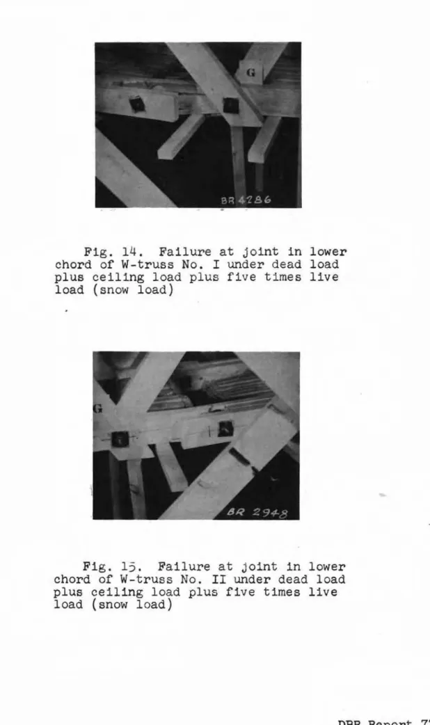
lb. persquare foot of horizontally projected roof area, failure occurred very suddenly in the lower chords of both trusses simultaneously near the panel point "G" (Figs.
1
and14-17).
Complete collapse was prevented by the upper chords of the trusses coming to rest on the crossbeams. Additional supports were installed as a precautionary measure against localfailures in weakened joints and end supports. By preventing complete collapse of the test assembly at failure of
24,443
lb., it was possible to obtain detailed photographic records of the points of most interest, namely, the joints near panel point"G" and the supports where spreading in the direction of the span occurred. The deformed shapes of W-truss No. II for each increment of live load as plotted from the deflection board records are shown in Figs.
4
to13.
4.
DISCUSSION OF RESULTSAlthough a period of twenty days was allowed for the joints in the trusses to bed down in the first loading phase, the changes in deflection during this period were small, as shown in Table II.
Under dead load plus ceiling load plU$ design live load, the largest net deflection at the end of the seven days of
sustained loading occurred at the point "F" (see Table III) on the lower chord of W-truss No. I. At this point the maximum value reached was
O.24n
inch. This value isapproximately one-third of the allowable deflection for a plastered ceiling. The recovery of deflection at this point,
24
hours after the removal of the live load was, however, only48.7
per cent. Similar values for the net deflections and recovelies were obtained for the remaining three points on the trusses.By comparing the deflections for the sixth and seventh days in Table III with the deflections in Table V for the initial readings and the readings after 24 hours, it can be seen that there was no significant change in the trend
indicated in Table III when the live load was re-applied for the third loading phase.
Under a symmetrical loading, the largest net deflection occurred again at point "F" on the lower chord of W-truss No. I, when 1.33 times the live load was applied to the upper chords from
"e"
to "E". This maximum value was 0.267 inch (see Table V), or approximately 1/1080 of the span. The recovery of deflection at this point, 24 hours after the superimposed load was removed, was 41.9 per cent. The corresponding value for the largest net deflection on thelower chords when the same loading was applied to the opposite roof slope was 0.244 inch at point "Gil, and the recovery 24 hours after the removal of the superimposed load was 42.7 per cent.
During the test to failure, i.e. sixth loading phase, the wire and pulley deflection apparatus was used to obtain the deformed shape of W-truss No. II as the increments of one-half design live load were applied. The maximum vertical
deflection reached before failure occurred took place at point "G" (Fig. 13) and reached a value of 0.56 inch. The corres-ponding value for point "F" was 0.50 inch. Both values were below the allowable deflection for a plaster ceiling of 1/360 of the span, or 0.80 inch. The fact that greater deflections did not occur can be explained by the resistance offered to vertical deflections by the tension developed in the lower chords under superimposed loads.
It will be noted when reviewing Figs.
4
to 13 that there was a trend toward セイッァイ・ウウゥカ・ spreading at the supports assuccessive increments of loading were applied. The total outward movement in the direction of the span at point "AII
prior to failure was 1/10 of an inch and the corresponding movement at point "Ell was approximately 2/10 of an inch, thus giving a total elongation of the lower chord of 3/10 of an inch. The total deflections of the upper chords measured at right
angles to the slope at point liB" and point "D" were 0.50 inch and 0.75 inch respectively.
When the lower chords failed under dead load plus ceiling load plus five times design live load, the test assembly and loading were supported so that photographs could be taken of the points of interest. Both lower chords of the two trusses failed at almost the same instant and at the same location. Figures 14 and 15 show the failures in W-truss No. I and No. II
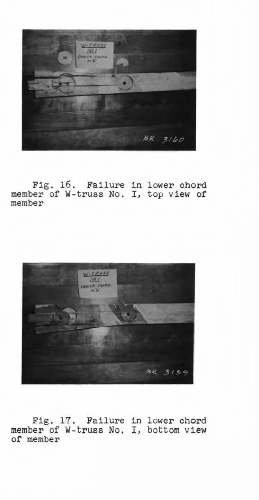
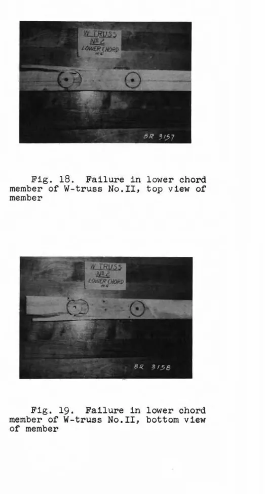
respectively. Additional features of the joint failures are shown in Figs. 16 to 19, which show the individual members that failed, after the trusses had been disassembled. Failure in each member was by shear and tension; the exact sequence of failure by these forces is difficult to determine.
5.
CONCLUSIONS (a) TrussesObservations made on the performance of the two trusses tested would not normally provide sufficient evidence upon which to base definite conclusions, but, making due allowance for the variability in wood, the general remarks which follow would apply in the over-all picture of similar components:
Firstly, because of the tensile forces induced in the lower chord members when the loads were applied, the vertical deflections of the members which normally support the ceiling in a house did not exceed the
maximum allowable deflection of 1/360 of the span for exterior plaster finish, even at incipient failure;
Secondly, the method used for fastening the joints of the trusses appears to be satisfactory, L e. there was very little イ・ャ。エゥカセ movement in the form of slippage between members until twice design load was reached;
Thirdly, since five times the design live load recommended by the National Building Code,
1953,
was reached before failure occurred, the strength of the trusses was more than adequate.(b) Testing Method
In general, the method of testing the trusses was satis-factory. It was found that the standard lead weights were very convenient for this type of loading test. The loads could be applied and removed without difficulty, and when the weights were not being used they could be neatly piled to one
side of the test assembly.
For the test to failure it was found that the pea-size crushed stone could be taken from the floor of the project area and transported by the overhead crane to the trusses without undue difficulty. Transporting of the crushed stone
by the crane, however, was slow. Moreover, considerable preparations were necessary to confine the crushed stone to the tributary roof area, and, unless the crushed stone was dampened by water before it was shovelled into the bucket
and dumped on the trusses, the dust from it was objectionable. The accuracy of the load on the trusses at any particular time was questionable because of the frictional losses between the crushed stone and the bulkheads. The exact amount of
friction developed during this test is not known; however, it is thought that the effect on the results is not appreciable.
6.
GENERAL DISCUSSIONIt may be useful to add some general thoughts on possible future work in this field.
The tests on these two trusses, which were designed
according to accepted design methods, that is, using allowable stresses, showed that an excessively high load safety factor resulted (the load safety factor being the ratio of load at failure to design load). In many structures the load safety factor exceeds the stress safety factor (the stress safety factor being the ratio of stress at failure to the allowable stress in the material). Thus the problem of the choice of an adequate load safety factor arises in the use of the test results. In other words, what mUltiple of the design load should the trusses be able to carry ?
In considering this question it seems that a comfarison of roof trusses with conventional roof constructions Joist and rafter construction) should be included in this study, as at the present time only trusses have to be designed according to accepted engineering principles. The test cf the two trusses described in this report can, therefore, be regarded as the first step only in a general investigation of the strength plovided by conventional as well as truss
construction. It is the intention of this Division to continue the work reported here with further studies aimed at the
development of an equitable basis for a balanced design in conventional and trussed roof constructions.
7. BIBLIOGRAPHY
Dalgleish, D. Timber Roof Trusses for Domestic Buildings.
Commonwealth Experimental Station, Sydney, Australia. September, 1949.
Expansion-Attic Truss. House and Home. September, 1952.
p. 110.
Hansen, Howard J. 'Design Loads for"Wooden Roof Trusses.
Agricultural and Mecbanical College of Texas.
Bulletin No. 74. Fourth Series, Vol. 13, No. 17.
December 1, 1942.
Housing and Home Finance Agency. Wood Roof Trusses for Small
Dwellings. Reprinted from HHFA Technical Bulletin
No.2 (January, 1948). United States Government
Printing Office. Technical Reprint Series No.2.
Washington, U.S.A. February, 1950.
Stern, E. George. Nailed Trussed Rafter of 24-ft. Span and
3 in 12 Pitch. Virginia Polytechnic Institute, Wood
Research Laboratory, Blacksburg, Virginia. April, 1954.
Timber Engineering Company. Design Manual for Teco Timber
Connector Construction. Teco Technical Series No.1.
Washington 6, D.C. 1943 Ed., Revised 1950.
Ulrey, Harry F. Nails Make Good Joints for Trussed Rafters.
Practical Builder. October, 1953. p. Ill.
University of Illinois. Trussed Roof-Frame for ャセ Storey
Houses. Small Homes Council. Urbana, Illinois.
University of Illinois.
"w"
Truss for 20 I-8" to 32' -8" spans. Small Homes Council. Urbana, Illinois.University of Illinois. 3/12-Slope for 20'-8" to 30'-8" spans.
LOADING SCHEDULE Loading Phase 1 2 3 4 5
Magnitude of Test Load
ceiling load plus dead load (shingles)
ceiling load plus dead load (shingles) plus design snow load
as in "211
as in
"1
11 plus1.33 x
design snow loadC to E
as in
"1"
plus1.33
x design snow loadA to C Duration of Loading 20 days
7
days24
hours24
hours24
hours Recovery Period None (load to remain to failure)24
hours24
hours24
hours24
hours6 test to failure in increments of
i
xDEFLECTIONS UNDER DEAD LOAD PLUS CEILING LOAD
(Moisture Content - Wセ and under)
W-truss No. I W-truss No. II
Settlement at Net Settlement at Net
Time Supports Deflections Supports Deflections
-A E G F A E G F Initial 0.029 0.009 0.041 0.067 0.022 0.033 0.026 0.026 After 5 days 0.035 0.015 0.047 0.072 0.024 0.038 0.029 0.030 II 10 II 0.036 0.016 0.050 0.073 0.030 0.040 0.032 0.033 11 15 II 0.036 0.016 0.051 0.074 0.030 0.040 0.035 0.036 II 20 II 0.037 0.016 0.052 0.075 0.031 0.041 0.036 0.036
DEFLECTIONS UNDER DEAD LOAD PLUS CEILING LOAD PLUS ONE TIMES LIVE LOAD
(Moisture Content = 7% and under)
W-truss No. I W-truss No. II
Settlement at Net Settlement at Net
Time Supports Deflections Supports Def'lections
-A E G F A E G F Initial 0.145 0.099 0.215 0.232 0.126 0.136 0.186 0.207 Af'ter 1 day 0.151 0.103 0.222 0.237 0.133 0.140 0.195 0.215
"
2 days 0.153 0.105 0.225 0.239 0.135 0.141 0.197 0.217"
3"
0.153 0.105 0.227 0.240 0.136 0.142 0.200 0.220"
4"
0.154 0.106 0.227 0.240 0.137 0.143 0.201 0.221"
5"
0.155 0.107 0.229 0.244 0.139 0.144 0.201 0.221 II 6"
0.156 0.107 0.231 0.245 0.139 0.144 0.202 0.222"
7 II 0.156 0.108 0.235 0.246 0.140 0.144 0.205 0.224ONE TIMES LIVE LOAD REMOVED
Immediate 0.119 0.071 0.117 0.135 0.105 0.100 0.092 0.103
After 24 hours 0.114 0.067 0.112 0.126 0.101 0.100 0.086 0.096
Recovery after 24 hours: 52.3% 48.7% 58.0% 57.6%
(Moisture Content = Wセ and under)
Time
Initial A:fter 24 hours
W-truss No. I W-truss No. II
Settlement at Net Settlement at Net
Supports De:f1ections Supports De:f1ections
A E G F A E G F
0.152 0.105 0.235 0.249 0.135 0.141 0.205 0.222
0.155 0.108 0.238 0.258 0.141 0.144 0.216 0.234
ONE TIMES LNE LOAD REMOVED
Immediate 0.120 0.072 0.127 0.140 0.105 0.099 0.099 0.111
A:fter 24 hours 0.116 0.068 0.122 0.135 0.102 0.096 0.092 0.103
Recovery a:fter 24 hours: TXNWセ TWNWセ UWNTセ 55.9%
(Moisture Content
=
Wセ and under)W-truss No. I W-truss No. II
Time Settlement atSupports DeflectionsNet
Settlement at
Supports DeflectionsNet
A E G F A E G F 0.121 0.117 UQNWセ 0.23-5 0.243 0.092 0.091 SQNVセ 0.099 0.101
DEAD LOAD PLUS 1.33 TIMES LIVE LOAD C TO E, DEAD LOAD A TO C
0.131 0.104 0.149 0.262 0.114 0.141 0.131
0.132 0.108 0.152 0.267 0.117 0.145 0.133
1.33 TIMES LIVE LOAD REMOVED C TO E
0.072 PセQQT 0.157 0.104
0.070 0.113 0.155 0.103
RUNVセ TQNYセ
Immediate 0.118
After 24 hours 0.116 Recovery after 24 hours:
Initial
A.fter 24 hours
DEAD LOAD PLUS 1.33 TIMES LIVE LOAD A TO C, DEAD LOAD C TO E Initial After 24 hours 0.153 0.088 0.155 0.089 0.240 0.173 0.136 0.118 0.204 0.244 0.173 0.139 0.119 0.212 0.153 0.156 1 .33 TIMES LIVE LOAD REMOVED A TO C
Recovery after 24 hours: Immediate After 24 hours 0.120 0.117 0.072 0.145 0.069 0.140 42.7'/J 0.134 0.106 0.133 0.103 RSNQセ 0.100 0.096 0.101 0.097 UTNRセ 0.113 0.113 RWNVセ
-lO セRjNイコBsNrN 1- Y2 " OIA. BOLT SPLICE PLATE Z"X'; X 1'-7" SPAN:24' CAMBER= -'/4"
L
4-2"2I " S.R. 2 - ",;' OIA. BOLTSt
2- Z"X 4" QMRyセG S.R..."....-1- Y2" OIA. BOLT
Z-2lo2"S.R.J
1- Y2" OIA. BOLT
セ
A G f Eセ
I
# ::1;
セ
I
km
o, 1I Z, SCALE fT. FI GURE I(Photograph: Photogrammetry Section, Division or Applied Physics, N.R.C.)
per square foot of horizontally projected roof area). Note deflection board and wire and pUlley arrangement for recording deflections.
LE.GE.ND: SCALE.. OF LE.J.JGTHS: QセUQᄋPᄋ
- BE.FOI2.f. LOADltJG
--- AFnl2 LOADtWG
c
SCALE. OF defleNctioセsF
IGUQ,E.4
Df-AD LOAD'" C·E.JLIJ.JG LOAD
... Y1
LIVE. LOAD
c
AセZNNNMMMMMMMMMセNNNNNN[[NNNNMMMMMMMMZNNNNセ」イMMMMMMMMM]]Lセ
E-A'
---G'---
F' £1FIGur.a:: 5
D.L.+
C.L.+I
S...,O\" LOADc
- - - --G1 F' AセZMMMMMMMMMMGNNNNLクNLNGMMMMMMMMMNL[NNNN⦅⦅⦅ᆬGt⦅MMMMMNNNNZZZZZZNセ f. セ セFIGUf2E.
(0V.L.
+ C.L. + 1Y2
SNO\vLOAD
A t
A セi
F IGUQE.
7
D.L.+
C.L. +'2
SI-JO\JLOAD
c
BUZMNNNNZZNNNNMMMMセNZjlNKMMMMMMMMMZャセK⦅MMMMNNNNN[Z[NNZLセeN E,.l
FIGUf2E. 8 D.L.+C.L. +
21'.2
SNOV LOADc
FIGUI2E.
9
D.L.
+C.L.
+.3SJ.JO\v' LOAD
c
FfGUI2E. 10 D.L.+C.L'" 31'2 sセo|カG LOAD
FIG U12
E-
II
D. L. + C.
L. +4
S
t-J0
\v
LOA D
c
r:JGUJ2E.
1'2D.L.+ C.L.+
411
sセo|jLOAD
c
A'--=- - -
" G I\F
MMMMMセ E.' 1""'\ - - - - " I --." MMMセ ' V _ -(;1 F1F
IGUr2E, 13 D.L.+
C.L. + 5 SNO\'LOAD
INCJPJE.NT ,:AJLUQE.
load (snow load)
Fig. 15. Failure at joint in lower chord of W-truss No. II under dead load plus ceiling load plus five times live load (snow load)
Fig.
17.
Failure in lower chord member of w-truss No. I, bottom view of memberFig. 19. Failure in lower chord member of W-truss No.II, bottom view of member