HAL Id: inria-00071469
https://hal.inria.fr/inria-00071469
Submitted on 23 May 2006
HAL is a multi-disciplinary open access
archive for the deposit and dissemination of
sci-entific research documents, whether they are
pub-L’archive ouverte pluridisciplinaire HAL, est
destinée au dépôt et à la diffusion de documents
scientifiques de niveau recherche, publiés ou non,
Networks
Guillaume Chelius, Claude Chaudet, Natalie Whitlock
To cite this version:
Guillaume Chelius, Claude Chaudet, Natalie Whitlock. Ad Hoc Mobility Notification in Wireless
Infrastructure Networks. [Research Report] RR-5113, INRIA. 2004. �inria-00071469�
a p p o r t
d e r e c h e r c h e
TH `EME 1
Ad Hoc Mobility Notification in Wireless
Infrastructure Networks
Guillaume Chelius — Claude Chaudet — Natalie Whitlock
N
◦
5113
F´evrier 2004
Networks
Guillaume Chelius , Claude Chaudet , Natalie Whitlock
Th`eme 1 — R´eseaux et syst`emes Projet Ares
Rapport de recherche n◦ 5113 — F´evrier 2004 —28pages
Abstract: Hybrid networks composed of a wireless infrastructure network providing In-ternet access to an underlying ad hoc network are more and more attractive due to their low installation cost. In these all-wireless environments, performance is a key issue as radio bandwidth is scarce. Handoffs management is particularly important as these networks are likely to be highly mobile. Mobility notification should therefore be optimized in order to limit signaling overhead while keeping a good reactivity against terminals mobility. This article presents and studies by simulation different level optimizations applied to a modified Cellular IP protocol.
hoc avec infrastructure sans fil
R´esum´e : Les r´eseaux hybrides, compos´es d’un r´eseau d’infrastructure sans-fil, fournissant connexion Internet et services `a un r´eseau ad hoc, pr´esentent un attrait ´evident ´etant donn´e leur faible coˆut d’installation. Dans ces r´eseaux totalement sans-fil, obtenir de bonnes per-formances n’est pas ais´e compte tenu de la faible bande passante offerte par le lien radio. La notification de la mobilit´e est particuli`erement importante dans ce type de r´eseaux et doit en cons´equence ˆetre optimis´ee afin de limiter le volume de trafic de contrˆole ´echang´e tout en conservant une r´eactivit´e adapt´ee face `a la mobilit´e des terminaux. Ce rapport pr´esente une ´etude par simulation de diff´erentes optimisations apport´ees au protocole Cellular IP et r´ealis´ees `a diff´erents niveaux.
Handoffs management is particularly important as these networks are likely to be highly mobile. Mobility notification should therefore be optimized in order to limit signaling over-head while keeping a good reactivity against terminals mobility. This article presents and studies by simulation different level optimizations applied to a modified Cellular IP protocol. Mots-cl´es : R´eseaux hybrides, r´eseaux sans fil, mobilit´e, handover, handoff, Cellular IP
1
Introduction
Wireless communications have to play a crucial role in computer networks. They offer open solutions to provide mobility and services where the installation of complex wired infra-structure is not possible. Several technologies are currently available. The IEEE 802.11 [14], finalized, around 1997, was one of the first standard for local wireless networks to have hard-ware implementations. In 1999, IEEE 802.11b [14] has extended the initial specifications to allow the physical layer bandwidth to reach 11 Mb/s and to support multi-rate networks. IEEE 802.11a [14] will soon be completely available. It allows transfer rate up to 54 Mb/s. In 2000, the Wireless Ethernet Compatibility Alliance (WECA1
) was created at the same time as the Wi-Fi2
certification program, ensuring interoperability between the different products.
Bluetooth [11]3
is an emerging technology which main characteristics are a short range, a low energy cost, and a low design cost. It was initially designed to replace point-to-point and point-to-multipoint connections and will probably become another important wireless network platform. Though IEEE 802.11 and Bluetooth operate on the same frequency band (2.4 GHz), these two technologies have distinct application areas and will probably reveal complimentary.
Bluetooth and IEEE 802.11 are not the only technologies for wireless networks. Some other specifications exist, such as the HomeRF [17] standard which proposes another solu-tion for wireless communicasolu-tions. The European Telecommunicasolu-tion Standards Institute (ETSI) BRoadband Access Network (BRAN) is currently working on HiperLAN/2 [25], a connection-oriented technology integrating QoS services at the MAC layer.
With the exponential growing of wireless communications, a wide range of wireless devices has been released. In the same time, the number of cellular phones has signific-antly increased. The Internet becomes pervasive and is now bound to cellular networks. In this context, the development of protocols enabling the support of wireless communica-tions must be used as an integrator. This concept is sometimes called “fourth generation networks”. Research on wireless networks has roughly been concentrating on two distinct themes. The first one aims at extending the edge of infrastructure networks by the integra-tion of a last wireless hop. The radio connectivity is provided by Base Staintegra-tions at the edge of the network. The second theme concerns infrastructure-free and auto-organized wireless networks: Mobile Ad hoc Networks (MANet [9, 12]).
The generalization of a wireless link as last IP link increases the use of IP in mobile situations. In the Internet, packets are forwarded from an IP source address to an IP destin-ation address. IP addresses have both roles of identifiers and locators. As communicdestin-ations are interrupted when either the source’s address or the destination’s addres changes, IP mobility support is not possible without the addition of new mechanisms. In order to solve this problem, Mobile IP (MIP [19]) has been introduced for the IPv4 and IPv6 protocols stacks enabling mobility while keeping a constant IP address.
1 http://www.weca.net 2 http://www.wi-fi.net 3 http://www.bluetooth.com
Mobiles connected to the Internet via a wireless medium are likely to frequently change the access point they are attached to. In this configuration, the MIP mobility management requires the exchange of several messages wasting at least several seconds. A hierarchical MIP architecture has been designed in order to reduce the signaling traffic in the Internet. For micro-mobility, Cellular IP (CIP [24]) was proposed. CIP is based on the cellular organization of 2G Cellular telephony networks and propose solutions to efficiently support fast inter-cells mobility (handoff ) and paging. In order to be used in wide networks, CIP was designed to inter-operate with Mobile IP. In this context, MIP manages mobility between cellular networks while CIP manages mobility within the cellular networks.
MANets require neither base stations nor fixed infrastructure. An ad hoc network is a collection of terminals equipped with wireless interfaces. Communications are limited by radio interface ranges. In order to realize multi-hops communications, an ad hoc node acts as a router for other nodes traffic and uses other ad hoc nodes as routers for its own traffic. An ad hoc network must be adaptive and auto-organized. Mobile users may join or leave the network at any time.
Research efforts aiming at merging cellular wireless and ad hoc networking have been recently increasing [5,26,6,13,2,23,7]. Hybrid networks, the extension of cellular network using ad hoc connectivity, offer obvious benefits. On one hand, they allow an extension cellular networks range using ad hoc connectivity and on the other hand they provide a global Internet connectivity to ad hoc nodes. However, deployment of a wired cellular infrastructure still represents a high cost as well as a lot of constraints. Both costs and constraints can be reduced if we replace the wired infrastructure network by a fully wireless one. The infrastructure network becomes a collection of static wireless nodes acting both as base stations and infrastructure routers. Infrastructure communications become wireless multi-hop communications. As the wireless medium really differs from the wired one (pervasive medium, non isolated links, higher latency and lower bandwidth), the design of classical micro-mobility protocols must be rethought and if necessary altered. As it seems hard to achieve as good performances in a wireless hybrid network as in a wired one, a deeper attention must be given to each layer of the networking stack in order to design protocols in adequation with the wireless medium characteristics.
In this article, we study how ad hoc node mobility/handoffs must be notified in the wireless infrastructure of a wireless hybrid network in order to achieve the best performances. Several strategies are proposed, simulated and compared for both the MAC layer and the routing layer. The article is organized as follows. An overview of the Cellular IP architecture and protocol is given in section2. Section3presents several hybrid network routing schemes and details the consequences of using a wireless medium in the infrastructure as well as the testbed that was used for simulations. Several strategies for mobility notification frame transmission are compared in section 4. Section 5 addresses the optimizations related to the ARP protocol and studies the impact of interface queue length on data packet delivery. Finally in section 6, we propose and compare several mechanisms to reduce the signaling overhead in the wireless hybrid network.
2
Micro-mobility protocols
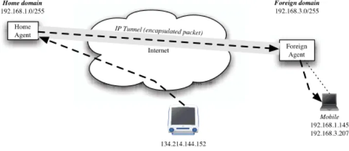
Within the Internet architecture, Mobile IP [19] has been designed to extend the IP frame-work in order to support the mobility of users between different locations. A mobile host connecting to the Internet in a foreign domain will initiate a dialog between its attach-ment network and its originating network in order to create an IP tunnel between these two locations, as shown in Figure1, making its mobility transparent from its peers. In particu-lar, this architecture concerns the management of user movement at a large scale, between different wide access networks connected to the Internet.
Internet Home Agent Foreign Agent Foreign domain 192.168.3.0/255 Home domain 192.168.1.0/255 Mobile 192.168.1.145 192.168.3.207 134.214.144.152
IP Tunnel (encapsulated packet)
Figure 1: A typical Mobile IP configuration
The IP tunnel setup requires the exchange of messages through the Internet and should not be performed too often. Running this scheme each time a mobile attaches to a new access point in the visited domain would introduce a high latency, frequent packet loss and a signaling overhead in the handoff procedure. Micro-mobility management addresses these problems by providing mechanisms to manage user movements at a local level, and therefore to allow scalability of user mobility management.
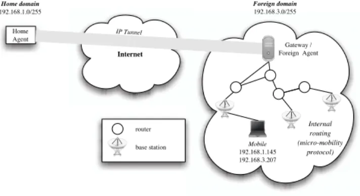
To achieve low latency and seamless handoffs, micro-mobility protocols usually define a hierarchical architecture, as represented in Figure2. A Gateway plays the role of Mobile IP proxy and foreign agent. Routing within this micro-mobility domain is specific and often closely tied to the micro-mobility protocol. In order to enhance scalability, reduce signaling and save power, these protocols often provide paging techniques to keep trace of idle mobile hosts.
Currently two IETF working groups are studying micro mobility due to the large amount of interest and necessity of a scalable deployment. The Mobile IP working group addresses the problems related to fast handoffs while the Seamoby working group aims to enhance paging techniques. Descriptions and performance comparisons of micro-mobility protocols such as Cellular IP [24], Hawaii [22], Hierarchical Mobile IP [10] and Edge Mobility [18] regarding handoffs have been published in [3,4]. We will particularly focus on Cellular IP due to its large scale deployment and the numerous proposals for its use in conjunction with ad hoc networks [2, 23, 26]. The Cellular IP (CIP) protocol presented by Columbia
Internet Home Agent Foreign domain 192.168.3.0/255 Home domain 192.168.1.0/255 Mobile 192.168.1.145 192.168.3.207 IP Tunnel Internal routing (micro-mobility protocol) router base station Gateway / Foreign Agent
Figure 2: Mobile IP and micro-mobility support.
University and Ericsson was designed to provide fast and smooth handoff between Base Stations (BS) in local domains connected to the Internet by a Gateway. Inter-domain mobility still relies on Mobile IP, while intra-domain routing is performed hierarchically. Routing Overview Within Cellular IP, location management and handoff support are integrated and operate on Mobile Hosts, Base Stations and Internet Gateways. Routing is based on host routes for the Mobile Host through all the Cellular IP nodes on the path of the Mobile Host to the Gateway. Each Cellular IP infrastructure node has an up-link and several down-link neighbors. CIP uses mobile originated data packets to maintain reverse path routes. CIP infrastructure nodes monitor mobile originating packets and maintain a distributed hop-by-hop location database that is used to route packets to Mobile Hosts called a Routing Cache. To keep its route cache mappings valid, the Mobile Host regularly transmits route update packets at regular intervals called route-update time. These packets are empty data packets addressed to the Gateway.
Up-link Route Maintenance (gateway advertisement) Up-going routes, from the Base Stations to the Gateway, are updated by regular flooding of the access network by the Gateway. A Cellular IP Gateway periodically broadcasts a beacon packet that is flooded across network Base Stations, which record the interface they last received this beacon through and then proceed to use it to route packets towards the Gateway. Up-going packets are routed towards the Gateway in a hop-by-hop manner using these routes and are used to help keep track of the emitting mobile’s location and initiate route updates if needed. To address situations where no up-going packets are transmitted, mobiles can regularly transmit empty route update packets towards the Gateway. In both cases, old routes are discarded by soft state timeouts.
Down-link routes maintenance (semi soft and hard handoff ) In the micro-mobility domain, mobiles elect one Base Station as a connecting point to the network. Mobile emitted packets are directed to this Base Station and forwarded to the Gateway or according to the CIP routes. Mobile intended packets are forwarded to the mobile through the Base Station. Base Stations periodically advertise their presence by using a BS advertisement packet. After moving, the mobile will change its connecting Base Station and update up and down-going routes performing handoff. Two types of handoff are possible. Semi-soft handoff requires the mobile to attach to both Base Stations while performing the handoff and to send an explicit route update message to notify the Gateway. While the host is still in contact with the old Base Station the semi-soft packets configure route cache mappings associated with the new Base Station and after a semi-soft delay, the host can perform a regular handoff. Semi-soft delay ensures that by the time the host tunes its radio interface to the new Base Station its down-link packets are delivered through both the old and new Base Stations, minimizing packet loss.
Hard handoffs require no particular signaling as handoffs and location tracking are per-formed by access routers snooping data packets and route update packets from the mobiles, thus no particular signaling is required. This type of handoff trades some packet loss for minimizing handoff signaling rather than trying to guarantee zero packet loss. The Mobile Host tunes it’s radio interface to a new Base Station and sends a route update packet which creates a route cache mapping on route to the Gateway. Hence, configuring the down-link route to the new Base Station. The mappings associated with the old Base Stations are cleared as the associated timers expire rather than explicitly.
3
Wireless Hybrid Network
Internet
Infrastructure node
Mobile (ad hoc enabled) node gateway
router
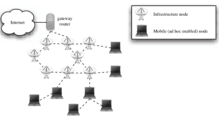
Figure 3: Wireless access network with underlying ad hoc network
The global architecture we are interested in is depicted in figure 3. It is composed of a wireless infrastructure network extended by a general Mobile Ad-Hoc Network (MANet).
This differs from the work done in [5] since the infrastructure network is wireless and the ad hoc connectivity may extend further than two hops. The infrastructure network is composed of wireless nodes which all act simultaneously as infrastructure routers and Base Stations. In other terms, communication in the infrastructure network transits through the wireless medium and may follow multiple hop routes since Base Stations may be out of range of each others. In this article, we focus on the ad hoc nodes mobility notification process within the wireless infrastructure network and do not compare routing strategies in hybrid networks. Such a study may be found in [26]. However, we briefly detail some hybrid architectures and their routing schemes in this section. We also present the impact of using a wireless medium in the infrastructure network.
3.1
A wireless hybrid architecture
Internet
gateway router
Ad hoc Network
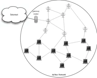
Figure 4: Unipolar hybrid architecture
Routing in an hybrid network may follow different strategies. We have mainly identi-fied three of them and a more complete classification may be found in [6]. The first one consists in applying an ad hoc routing protocol in the whole hybrid network, considering the infrastructure network as a static ad hoc one and handling micro-mobility as ad hoc mobility. This strategy is depicted in figure4. Works done in [1,13] use this strategy. If one of its strong point is simplicity, all mobility being handled by the ad hoc routing protocol,
it presents several drawbacks, especially regarding scalability and the lack of an appropriate fast mobility support.
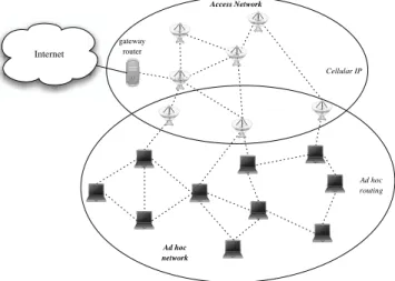
Internet gateway router Access Network Cellular IP Ad hoc network Ad hoc routing
Figure 5: Bipolar hybrid architecture
[23, 26, 2] propose a second strategy where the hybrid network is, in term of routing, splitted in two entities, the infrastructure network and the ad hoc one. Routing in the ad hoc network is handled by an ad hoc routing protocol and the micro-mobility support is provided by Cellular IP which manages routes to the ad hoc mobile nodes in the infrastructure network. This strategy is depicted in figure 5. Cooperation of the two routing protocols, Cellular IP and the ad hoc protocol, requires some modifications in their functioning. Works performed in [2, 23] only consider reactive routing protocols, DSR [16] and AODV [20] respectively and in consequence, focus on avoiding ad hoc route breakage while a mobile performs a CIP handoff.
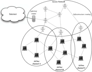
[7] presents a third alternative strategy where the use of the Ana addressing architec-ture enables the partition of the hybrid network in several logical sub-networks in which different routing schemes may be applied. Among the several sub-networks, one maps the infrastructure network and the remaining ones are each associated to one Base Station and its depending ad hoc nodes. An example is given by figure6. In each ad hoc sub-network, routing is handled by an ad hoc routing protocol. In the infrastructure sub-network, a CIP-like protocol is in charge of managing down- and up-going infrastructure routes to ad hoc mobile nodes. The interface between these routing protocols is performed by each Base Station which behaves as a Gateway for ad hoc nodes and exports ad hoc node location in the infrastructure using the CIP-like protocol. Base Stations participate to both the ad hoc and the CIP-like routing.
Internet gateway router Access Network Infrastructure routing Ad hoc channel A Ad hoc channel B Ad hoc channel C
Figure 6: Multi-polar hybrid architecture
3.2
Interoperability of CIP and ad hoc routing
Merging an ad hoc routing protocol and a micro-mobility protocol may require slight modi-fications to ensure inter-operability, efficiency and lower costs for both protocols. First, since all ad hoc nodes must be able to communicate with each other independently from the Base Station they are connected to, it is necessary to have all of them transmitting on the same wireless medium. As we can expect a mobile to communicate with other mobiles and Base Stations using the same radio interface, Base Stations must also share the same wireless medium, hence the same frequency. In consequence, handoffs are logical and not physical as it is not necessary for the mobile to tune its radio when performing handoff. As a mobile is able to listen to several Base Stations simultaneously, hard handoffs never occur and soft handovers are therefore redundant. Packets transmitted through an old infrastructure path will continue to be received as long as the mobile remains covered by the Base Station. Data delivery during soft-handover is achieved without the necessity of data traffic duplication.
Proactive and most reactive ad hoc routing protocols require the use of periodical control messages for topology dissemination and/or neighborhood discovery and management. As an example, OLSR [15, 8] (proactive) and AODV [20,21] (reactive) both use a Hello pro-tocol where nodes periodically broadcast Hello packets to their neighborhood. In addition, OLSR periodically performs broadcast of TC packets for topology dissemination. In the rest of this article, we will refer to these periodical control packets as generic ad hoc packets. The role of these periodically emitted packets is locally redundant with the emission of CIP BS advertisementby Base Station and CIP route update by mobile nodes. Information contained by BS advertisement may be easily integrated into ad hoc packets of Base
Sta-tions and the received ad hoc packets of mobile nodes may be interpreted as route update by the Base Stations, which in turn may modify and forward them along the infrastructure routing tree. The primary interest for this scheme is to lower the control traffic by merging information from both protocols into a single packet. Secondly this scheme ensures both protocols are being tuned on a similar mobility reactivity speed. The main consequence for the micro-mobility protocol is that the equivalent of route update packets are initially emitted by mobile nodes in broadcast whereas they were originally sent using unicast frames in Cellular IP.
3.3
Experimental Testbed
We performed our simulations using the network simulator NS-24. The topology network
used for the testing environment of this hybrid wireless network consists of 9 wireless infra-structure nodes with the addition of 2 to 64 mobile nodes. Under the Random Waypoint Mobility model, mobile nodes travel towards a random destination at a random speed and then rest at the particular co-ordinates for a random time until moving to the next location. The maximum speed of the mobile nodes has been set to 50m/s. Constant Bit Rate data flow between the mobile nodes is simulated from 1 flow up to 32, where each flow is 5 packets of 500 bytes per second, i.e. 20 kbits/s. The packets are sent with a small jitter to avoid repeated simultaneous sending. For the simulations, unicast and broadcast packets are both transmitted at a bandwidth of 2 Mbits/s as this is the standard case in NS-2.
4
Comparing the Route Update strategies
The radio medium is far from being similar to a classical wire medium such as Ethernet and differs in several aspects. Wireless links are pervasive and not isolated due to the broadcast nature of the medium. In consequence, the topology of the infrastructure network is not efficiently mapped into a routing tree as it is in Cellular IP. Essentially it is not possible to uniquely identify an up-link neighbor as several routes may join a Base Station to a Gateway and hence the routing tree may be different at one time to another due to the dynamic creation through Gateway Advertisement flooding. Another difference between wired and wireless links is the medium transmission quality and efficiency as bandwidth is smaller and latency is greater in air. For comparison, the latency of an Ethernet link is around 0.2 ms whereas the latency of 802.11 in ad hoc mode is just higher than 1 ms. This difference in results lead to the fact that some design aspect chosen during the development of Cellular IP may no longer be appropriate. For example, the choice to transmit route updatepackets in unicast increases reliability however it also prevents routing along efficient paths in the infrastructure network and hence, must be rethought. Although the CIP paths are acceptable in unicast due to the low latency of wired links, the high latency of wireless links suggests that unicast may be inappropriate. Reliability of unicast and broadcast transmissions also differs in wire and wireless media.
4.1
Experimental protocol
The protocol we propose in order to study mobility notification in a wireless hybrid network is a slight derivation of Cellular IP which integrates the remarks in section3.2.
Every 0.2 s, mobile nodes broadcast ad hocpackets which contain the list of the mobile neighbors, other mobiles and Base Stations, and the identity of the Base Station the mobile has chosen to attach to. These packets play both the role of control packets for the ad hoc routing protocol and route update for the CIP-like protocol.
Infrastructure nodes, as already mentioned in section 3, also act like Base Stations as they communicate through a wireless medium and participate to ad hoc routing through the broadcast of ad hoc packets every 0.2 s. These ad hoc packets contain a list of mobile neighbors and advertise them as a Base Station. Here again, these ad hoc packets play both the role of control packets to the ad hoc routing protocol and BS advertisement for the CIP-like protocol.
Mobility notification is implicitly initiated by a mobile. As a Base Station receives an ad hoc packet from an attached mobile, it transforms the ad hoc packet into a CIP-like route update packet and forwards it to the infrastructure network Gateway through its up-link neighbor. In an infrastructure node, reception of a mobile ad hoc packet updates the route entry for this mobile and reception of a route update packet updates the down-going route to the mobile with the last forwarder as next hop. An infrastructure route has a lifetime of 0.5 s. By default, if no specific route is known, a data packet is forwarded toward the infrastructure Gateway. Mobile nodes always transmit their data packet to their Base Station.
4.2
Acknowledged broadcast
The IEEE 802.11 distributed coordination function (DCF) basically provides two MAC level modes for frame transmissions. Frames can be sent towards one particular node (unicast mode) or towards all the neighbors (local broadcast mode). Unicast frames require acknow-ledgment from the receiver. If the emitter does not receive an acknowacknow-ledgment, it concludes that the corresponding transmission has failed and continues to send the frame again until it receives an acknowledgment or until the maximum retransmission attempts limit has been reached for the particular frame. Unicast frames can also be protected, especially against hidden node situations, by using a Request to send - Clear to send (RTS-CTS) exchange prior to frame transmission. In this optional mechanism, an emitter willing to send a frame starts the exchange by sending a small RTS frame to which the emitter must respond with a CTS message if the medium is free in its neighborhood. When the emitter does not get the CTS frame back, the transmission is delayed. Both RTS and CTS frames are overheard by all neighbors which will delay their transmissions according to the information included in these frames. Broadcasted frames are neither protected by RTS-CTS, nor acknowledged. Therefore, correct reception cannot be guaranteed. But, if the same data rate is used, broadcasted frames are far more efficient when transmitting information to a set of neigh-bor nodes. Both strategies present advantages for route update messages transmission.
On one hand, unicast transmissions ensure a certain reliability and therefore can help in maintaining an accurate view of the topology among infrastructure nodes. On the other hand, broadcasted frames will allow the spread of the topology updates faster. Mixing the two approaches to obtain a more reliable broadcast could be profitable. In other words, we seek a way to acknowledge broadcasted frames among the infrastructure nodes and eventu-ally retransmit mis-received messages. Genereventu-ally, as broadcasted frames are received by an unknown number of nodes, acknowledging them is not straightforward. If every receiver ac-knowledged the frame, their multiple acknowledgment frames emitted simultaneously would collide. Therefore, acknowledging broadcasted frames requires the selection of one partic-ular neighbor to acknowledge frames, exactly as if the message was transmitted in unicast mode and every other mode was in a promiscuous reception mode. Such a strategy would be difficult to implement in a mobile context because the election of this particular peer would require frequent updates and there could always be confusion between the disappear-ance of the peer and the unsuccessful transmission of a broadcast frame. Nevertheless, this approach appears particularly well suited for our situation. As a hierarchical relationship is maintained between the infrastructure nodes, the election of the acknowledging node can easily be mapped on the routing tree maintained in this part of the network. Moreover, when a node emits a route update message, it is destined to its father in the routing tree. If other infrastructure nodes can overhear this message, they will also benefit from this in-formation, adding a route to the mobile and enabling a shortcut in the tree routing scheme of Cellular IP, although they are not the intended receivers. In the following paragraphs, we will compare the results we obtained for the three possible strategies for route update transmission: using unicast transmission, broadcast or acknowledged broadcast. In order to correctly study the differences between this three transmission modes, we will keep the tree routing scheme of Cellular IP and avoid taking the advantages offered by the broadcast and acknowledged broadcast modes in term of routing.
4.3
Simulation Results
First of all, we will compare three strategies at the MAC-level for route update messages transmission. Unicast mode represents the most reliable solution of all. Frames are preceded by an RTS-CTS exchange (which is optional but used here) and have to be acknowledged. On the other hand, broadcast mode trades reliability for speed. Frames are neither protected nor acknowledged. The acknowledged broadcast mode is, regarding reliability and speed, exactly as the unicast without the RTS-CTS exchange.
Basically, the more reliability is added in the frame transmission, the more medium occu-pancy it will represent. Sending a 36 bytes route update frame at a 2 Mb/s data rate takes on average 832 µs using broadcast, 1146 µs using acknowledged broadcast or unicast without RTS-CTS exchange and 1686 µs using unicast with RTS-CTS exchange. Nevertheless, using acknowledged broadcast or unicast, we could benefit from higher data rates (e.g. 11 Mb/s) transmissions.
With Cellular IP, each node will regularly emit ad hoc packets, each Base Station will regularly forward route update packets and relay gateway advertisement packets.
Sig-naling therefore can represent a high load when the network gets dense. SigSig-naling packets nevertheless carry useful information and should neither be lost, nor be delayed too much. Losing route updates will result in many routing table inconsistencies and delaying these packets too much will result in outdated information in the routing tables. Choosing between these two alternatives is difficult because protecting route update frames will increase the network load resulting in high delays and interface queue losses. However, not protecting these frames, will result in high losses due to collisions. In both cases, routing tables will contain errors.
Figure 7 presents the losses of data packets due to the absence of route towards the destination in the whole network for configurations where the medium is overloaded (more than 16 CBR data flows). This situation arises when a route has been deleted due to timeout and the new route has not yet been discovered or propagated. Data packets are forwarded to the Gateway, which is the root of the infrastructure network, that drops the packet. Unicast transmission of route update messages leads to the highest data packet loss rate, due to the delay introduced by the protection of signaling frames. Routes are not refreshed in time and routing tables entries disappear.
Broadcast-Ack Broadcast Unicast 32 48 64 Number of nodes 24 28 32 Number of flows 400 500 600 700 800 900 1000 Packets losses
Figure 7: Losses of CBR packets due to route disappearance
On the opposite, Figure8 presents the losses of data packets due to retransmissions by the infrastructure nodes. This situation happens whenever a mobile has moved but the routing entry in the infrastructure network still references the old base station. In this situation, broadcast transmission of route update frames leads to the highest loss number due to the low reliability of the signaling messages transmission.
Both strategies present advantages as well as drawbacks and it is difficult to determine which method will yield optimal results. Acknowledged broadcast is an ”in the middle” approach and could lead to better overall results in the end. Figure 9 represents the total
Broadcast-Ack Broadcast Unicast 24 32 48 64 Number of nodes 24 28 32 Number of flows 550 600 650 700 750 800 850 900 950 1000 Packets losses
Figure 8: Losses of CBR packets due to wrong routing entry
of packets that have been correctly transmitted in each of the simulations performed. As soon as the data flows saturate the medium, broadcast mode outperforms unicast mode by 25% in the best case. Unicast transmission of Route Update messages always results in the poorest performance, followed by acknowledged broadcast and broadcast.
The number of packet successfully delivered is highly dependent on the network load. When the network is not overloaded, the performances of the three strategies are equivalent. Then, when the network capacity is exceeded, the overhead introduced by the route update transmission mode results in a difference in the number of packets successfully transmitted. As transmitting a packet in broadcast mode requires less time than transmitting the same packet in unicast mode, the medium capacity is exceeded later with broadcast route update packets. Finally, performances become equivalent again when the network is overloaded regardless of the transmission mode.
5
Impact of gratuitous ARP or Queue length
Among all the causes of data packet loss, some are hardly avoidable, such as collisions in an overloaded radio environment or data forwarding failure due to the mobiles high mobility. Other losses are bound to parameters or protocols that could be modified. Examples are packets lost because of an unresolved ARP (Address Resolution Protocol) query or packets dropped in the queue between the routing stack and the MAC layer.
Broadcast-Ack Broadcast Unicast 4 8 1216 24 32 48 64 Number of mobile nodes 124 68
16 2428 32 Number of flows 0 200 400 600 800 1000 1200 1400 1600 1800
Packets successfully transmitted
Figure 9: Number of CBR packets correctly received
5.1
Gratuitous ARP
One cause of packet losses is due to Address Resolution Protocol (ARP) failures. When a new node appears in the network, packets destined to this node will be dropped until the correspondence between its IP address and its MAC address is made. The only way to fill the ARP cache is based on a specific request-response mechanism. When an unicast frame is destined to an IP address for which no corresponding MAC address can be found in the ARP table, a request is locally broadcasted and a response awaited. After several retrials, if no response is received, the data packet is dropped. Two reasons may be at the origin of the ARP handshake failure. The first one is a loss of some ARP packets due to collision or medium overloading and the second one is mobility. Consider a mobile which is loosing direct connection to its Base Station and for which the Base Station has not forwarded any data yet. If some data arrives to the Base Station, the ARP handshake will fail as direct communication with the mobile is no longer available.
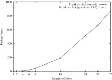
ARP protocol could benefit from the regular broadcasting of ad hoc packets done by each mobile node. While receiving a local ad hoc packet, a Base Station may extract both the IP and MAC addresses from the emitting mobile in order to fill the ARP table. This gratuitous ARP mechanism may only be performed on particular control packets as we must ensure that the IP source address matches the MAC source one. Figure 10 presents a comparison between the usual mode based on ARP requests and the optimized mode using broadcasted packets to fill ARP cache. Results are presented only for networks of 64 mobiles in Acknowledged Broadcast mode in order to enhance readability, as they are similar in other topologies and other transmission modes. These simulations show that the use of gratuitous ARP cache filling suppresses the loss of packets due to network initialization.
However, figure11 shows that the use of gratuitous ARP also leads to an increase of data packet loss due to an exceeded retransmission count. If gratuitous ARP prevents the loss of data packets due to ARP packet loss, it is impossible to avoid the data loss that was previously attributed to ARP loss but in fact was caused by mobiles mobility. Instead, this loss is now counted as exceeded retransmission count.
0 200 400 600 800 1000 1 2 4 6 8 16 24 28 32 Packets losses Number of flows Broadcast-Ack (normal) Broadcast-Ack (gratuitous ARP)
Figure 10: Comparison between normal behavior and the use of gratuitous ARP (Acknow-ledged Broadcast)
5.2
Queue length
Previous results indicated that delay in signaling packet transmission can have an impact on the network goodput due to route expiration. This problem cannot be solved by simply enlarging the route timeout, as the number of incorrect routes would increase subsequently. As packets conveying expired information should not be transmitted, decreasing the interface queue (i.e. the queue between routing and MAC level) length may have a positive impact on network performance. To study this parameter’s impact, we ran simulations using different interface queue lengths. Figure 12, represents the number of packets lost in this queue for queue lengths of 10 and 100 packets.
First of all, the amount of packets lost in interface queue is very large (up to 60 % of the total number of packet losses in the worst case with a queue length of 10 packets). Reducing this number of drops by increasing the queue length could significantly improve the packet delivery ratio but would also lead to a greater delay in signaling packets transmission, leading to an increase of wrong routes related drops.
0 200 400 600 800 1000 1 2 4 6 8 16 24 28 32 Packets losses Number of flows Broadcast-Ack (normal) Broadcast-Ack (gratuitous ARP)
Figure 11: Comparison between retransmission losses in normal behavior and the use of gratuitous ARP (Acknowledged Broadcast)
0 500 1000 1500 2000 2500 3000 3500 4000 4500 5000 1 2 4 6 8 16 24 28 32 Packets losses Number of flows
Queue length = 10 packets Queue length = 100 packets
Comparing the results for different drop causes on Figure12, Figure13 and Figure14, we can see that if the number of drops related to interface queue significantly decreases, the number of delay-related drops increases, especially when the medium gets overloaded.
0 200 400 600 800 1000 1200 1 2 4 6 8 16 24 28 32 Packets losses Number of flows
Queue length = 10 packets Queue length = 100 packets
Figure 13: Amount of packets lost due to route disappearance with different queue length
0 200 400 600 800 1000 1 2 4 6 8 16 24 28 32 Packets losses Number of flows
Queue length = 10 packets Queue length = 100 packets
Figure 14: Amount of packets lost due to retransmissions with different queue length Finally, Figure15shows the number of packets successfully transmitted for acknowledged broadcast mode using 10 packets and 100 packets long queues. Using long queue lengths
seems only to be profitable when the medium is not saturated. As soon as the medium gets loaded, decreasing delay shall be favored to increase Cellular IP performance.
200 300 400 500 600 700 800 900 1000 1100 1 2 4 6 8 16 24 28 32
Packets successfully transmitted
Number of flows
Queue length = 10 packets Queue length = 100 packets
Figure 15: Influence of the interface queue size on network performance
6
Optimization of the mobility notification
From the results of sections 4 and 5, we can deduce that the main challenge to improve data traffic delivery is to reduce the radio medium utilization. We have to reconsidered experimental protocol described in section4.1in order to lower the number of control packets its use requires.
6.1
Differential Route updates
kth
route update 1 2 3 4 5 6 7 8 10 11 12 Inter-period 0.2 s 0.3 s 0.4 s 0.6 s 0.8 s 1.0 s 1.2 s 1.4 s 1.6 s 1.8 s 2.0 s Timeout 0.5 s 0.75 s 1.0 s 1.5 s 2.0 s 2.5 s 3.0 s 3.5 s 4.0 s 4.5 s 5.0 s
Table 1: Time interval between two successive route update emissions.
Frequent route updates are necessary while the mobile performs a handoff. A new route has to be set up in the infrastructure network as fast as possible in order to avoid misrouting and losing of data packets. A first route update packet must be sent after the mobile’s
handoff to create the route. This sending must be repeated in short successive intervals of time in order to prevent the loss of the previous route update packets as their delivery is not reliable. After the route setup and while the mobile remains connected to the Base Station, frequent updates are no longer needed. The time interval between two consecutive updates may be increased in order to lower the number of control packets. However, the frequency of ad hoc packet emission may not be reduced as cellular stillness is far from meaning ad hoc stillness. In consequence, only a subset of the ad hoc packets may be forwarded by Base Stations as route update packets.
We introduce a flag in ad hoc packets to notify the Base Station whether or not the packet must be forwarded in the infrastructure as a route update. The flag is set by the mobile as it is the one which initiates the handoff. Table1 presents the different intervals between two successive route update while the mobile remains attached to the same Base Station. As a mobile performs a handoff, the route update frequency is reinitialized to its highest value. We call this mechanism differential route update.
6.2
Nack route
While using differential route update mechanism, route update emission intervals may be larger than the ad hoc packets period. This means that the link between the mobile and its Base Station is refreshed at a higher rate than the infrastructure down-going route to the mobile. In consequence, the Base Station may notice a mobile’s handoff long before the mobile’s route times out in the infrastructure. This route reminiscence may lead to incorrect routing and data packet loss. In order to prevent this phenomenon, a Base Station may, as soon as it has detected a mobile has left its cell, discard the route towards this mobile in the infrastructure. As routing incoherence between different infrastructure routers may lead to routing loops, it is not enough for the Base Station to only discard the route on its own. It should notify all infrastructure routers concerned by the now out-dated route, that it is no longer valid. This is realized by the Base Station emitting a route delete packet which is forwarded to the infrastructure Gateway along the same path as route update packets. This packet discards a mobile’s route in the infrastructure routers on its path.We call this mechanism nack route.
6.3
Nack only
If we carry on trying to reduce control traffic to its extreme, we can completely avoid multiple route update emission after a mobile handoff and send only one. This strategy is optimistic in the sense that it makes the supposition that route update packets may not be lost in the infrastructure. On the other hand, there will be no infrastructure route to the mobile and data packets will be dropped. Since only one route update is sent for each handoff and no refreshment is further performed, infrastructure routes have an infinite lifetime. To invalid an old route after a mobile handoff, Base Stations send a route delete packet, as explained in the previous section. This strategy sounds far from reliable as only one route
updateloss has catastrophic consequences, but it has the advantage of drastically reducing the control traffic.
6.4
Simulation Results
Simulations have been carried out for broadcast, unicast as well as acknowledged broadcast route update transmission modes. Usually, using the optimizations described above in these three transmission modes provides similar results when evaluating the optimizations per-formance. Even if the total numbers of packets successfully transmitted are not the same, the phenomenons described below are the same for the three modes, therefore we will only present figures for one single transmission mode. Simulations show that the number of nodes in the network has a much lower influence on overall performance when compared to the number of data flows in the network. Therefore, for readability, we will only present results for networks of 64 mobile nodes, as results are also similar when considering fewer nodes.
0 1000 2000 3000 4000 5000 6000 7000 8000 9000 1 2 4 6 8 16 24 28 32
Route Update Sent
Number of flows
Broadcast-Ack (normal) Broadcast-Ack (Diff Rupd) Broadcast-Ack (Nack - Route) Broadcast-Ack (Nack Only)
Figure 16: Total number of route update messages sent (64 mobiles; acknowledged broad-cast)
The first objective of these optimizations is to limit the amount of bandwidth wasted in signaling. Redundant information transmission is not necessary, unless there is a high probability of losing messages. Even in this last situation, the right amount of redundancy should be sought. Figure16 shows the total number of route update packets sent by the infrastructure nodes. As expected, optimizations described previously greatly reduce the number of sent packets.
To evaluate the performance of the different routing strategies, we will look at the influ-ence of the different optimizations on the routing tables validity. Figure 17 represents the number of data packet losses due to route disappearance, i.e., no route exists to reach the
0 200 400 600 800 1000 1200 1 2 4 6 8 16 24 28 32 Packet losses Number of flows Broadcast-Ack (normal) Broadcast-Ack (Diff Rupd) Broadcast-Ack (Nack - Route) Broadcast-Ack (Nack Only)
Figure 17: Amount of data packets lost due to route disappearance (64 mobiles; acknow-ledged broadcast)
destination mobile, neither in the Base Station to which the sender is attached to, nor in the Gateway. These drops occur when a route expires in the whole network before the new route to the mobile has been propagated. When the medium is lightly loaded, optimizations seem to increase the number of drops at the Gateway. But as soon as the medium gets overloaded, the Nack Only optimization which reduces the load due to signaling packets, is highly efficient. As route update messages represent a high load, the medium saturation point is postponed. However, losing a route update message has a much greater impact with Nack Only optimization, that’s why performance collapse again under a high data load. However, Figure 18 shows the number of data packets lost due to outdated entries in the routing tables. The Base Station in charge of the receiver tries to forward the data frame to the mobile, gets no acknowledgment in return, concludes there has been a collision and retries to forward the frame until the retransmission counter is exceeded. These losses are also due to repeated collisions resulting in retransmissions but analysis of the trace files show that this cause is marginal compared to mobility-related losses. These results show that the more optimizations we add, the more the routes are outdated. This is due to the increasing delay between two route update packets sending, resulting in a increasing route timeout.
Optimizations described here lead to the same kind of discussion as the one on the different ways to transmit route update messages. One one hand, we will try to send as few route update frames as possible, but we will be less reactive to mobility and on the other hand, over-occupying the medium will delay data packets and raise the number of packets lost due to collisions. Figure 19 represents the total amount of data packets successfully delivered. If simple Differential Route Update mode always shows good performance, other
0 200 400 600 800 1000 1200 1 2 4 6 8 16 24 28 32 Packet losses Number of flows Broadcast-Ack (normal) Broadcast-Ack (Diff Rupd) Broadcast-Ack (Nack - Route) Broadcast-Ack (Nack Only)
Figure 18: Amount of data packets lost due to errors in routing tables (64 mobiles; acknow-ledged broadcast) 0 200 400 600 800 1000 1200 1400 1 2 4 6 8 16 24 28 32
Packets successfully transmitted
Number of flows
Broadcast-Ack (normal) Broadcast-Ack (Diff Rupd) Broadcast-Ack (Nack - Route) Broadcast-Ack (Nack Only)
Figure 19: Amount of data packets successfully transmitted (64 mobiles; acknowledged broadcast)
mode performances are load-dependent. Nack Only optimization is rather good when the medium is overloaded but represents a loss of performance when there is no real need for saving bandwidth. 0 200 400 600 800 1000 1200 1400 1 2 4 6 8 16 24 28 32
Packets successfully transmitted
Number of flows
Unicast (No optimisation) Broadcast (Diff RUP + grat ARP)
Figure 20: Number of packets correctly transmitted in normal mode and with optimisations To conclude this study, Figure 20 shows the total number of data packets correctly transmitted by a regular Cellular IP compared to a modified version in which route update packets are broadcasted and gratuitous ARP and differential route update optimizations are activated. This optimized Cellular IP leads to the best performance, enhancing the overall data throughput by up to 40%.
7
Conclusion
In this article, we presented several possible modifications of the Cellular IP protocol for enhancing its performance in a wireless hybrid context. These modifications, concerning routing, MAC layer as well as inter-layers architecture, show that network performance can be increased by up to 40 %. These results can still be enhanced, for example by implementing optimizations of the routing scheme related to the broadcast transmission of signaling frames. These results especially show how micro-mobility protocols derived from wired protocols are inadequate in a wireless context. Mechanisms that have proved themselves worthy in regular networks such as reliable unicast transmission should be left aside in most situations.
Performance should not be expected to get similar to those obtained in wired networks. Nevertheless, the efficiency of wireless hybrid networks can be increased. This work shows that the key issue regarding network performance is the network load. This load can be decreased on one hand by reducing the global signaling volume as studied here and on the
other hand by designing suited radio interfaces and medium access protocols. The separated signaling channel mechanism, allocating a particular frequency, time slot or CDMA code to control traffic, widely used in cellular telephony networks might lead to further performance enhancement. Nevertheless, actual wireless hardware does not allow this due to the long channel switching delay.
The path towards efficient wireless hybrid networks still requires many issues to be addressed. Ad hoc networks auto-configuration or addresses allocation allowing mobiles to determine their Mobile IP Care-of-address are key examples. MAC protocols should also allow a larger cooperation between link level and routing level. Finally, security is also a major issue to which the union of cellular and ad hoc networks can provide elegant solutions, as ad hoc networks, usually infrastructureless, could now rely on a backbone. All these research fields will find an increasing interest, as on the opposite of pure ad hoc networks, wireless hybrid networks could quickly become commercially interesting, as they represent a low-cost solution to the wireless Internet access providing.
References
[1] M. Benzaid, P. Minet, and K. Al Agha. Integrating fast mobility in the OLSR routing protocol. In IEEE MWCN, Stockholm, Sweden, September 2002. IEEE Communica-tions Society.
[2] R. Bhan, A. Croswell, K. Dedhia, W. Lin, M. Manteo, S. Merchant, A. Pajjuri, and J. Thomas. Adding ad hoc Network Capabilities to Cellular IP. Technical report, www.columbia.edu.
[3] A. Campbell, J. Gomez, S. Kim, Z. Turanyi, C-Y. Wan, and A. Valk´o. Comparison of ip micromobility protocols. IEEE Wireless Communications, 9(1):72–82, February 2002.
[4] A. Campbell and J. Gomez-Castellanos. Ip micromobility protocols. ACM SIGMOBILE Mobile Computing and Communications Review, 4(4):45–53, October 2000.
[5] R-S. Chang, W-Y. Chen, and Y-F. Wen. Hybrid wireless network protocols. IEEE Transactions on Vehicular Technology, 52(4):1099–1109, July 2003.
[6] H-C. Chao and C-Y. Huang. Micro-mobility mechanism for smooth handoffs in an integrated ad-hoc and cellular ipv6 network under high-speed movement. IEEE Trans-actions on Vehicular Technology, 52(6):1576–1593, November 2003.
[7] G. Chelius and ´E. Fleury. Design of a hybrid routing architecture. In IEEE MWCN, Singapore, November 2003. IEEE Communications Society.
[8] T. Clausen and P. Jacquet. Optimized link state routing protocol. RFC 3626, IETF, September 2003.
[9] S. Corson and J. Macker. Mobile Ad hoc Networking (MANET): Routing Protocol Performance Issues and Evaluation Considerations. IETF RFC 2501, January 1999. [10] E. Gustafsson, A. Jonsson, and C. Perkins. Mobile ipv4 regional registration. Internet
draft – draft-ietf-mobileip-reg-tunnel-08.txt, November 2003.
[11] J. Haartsen, M. Naghshineh, J. Inouye, O. Joeressen, and W. Allen. Bluetooth: Vision, Goals, and Architecture. Mobile Computing and Communications Review, 2:38–45, 1998.
[12] Z. Haas, J. Deng, B. Liang, P. Papadimitratos, and S. Sajama. Wireless Ad hoc Networks. ENCYCLOPEDIA, 2002.
[13] Y-Z. Huang. Dynamic adaptive routing for heterogeneous wireless network. Master’s thesis, National Central University, West Lafayette, USA, 2001.
[14] IEEE Standard for Information Technology Telecommunications and Information Ex-change between Systems. Local and Metropolitan Area Network – Specific Requirements –Part 11: Wireless LAN Medium Access Control (MAC) and Physical Layer (PHY) Specifications, 1997.
[15] P. Jacquet, P. Muhletaler, A. Qayyum, A. Laouiti, T. Clausen, and L. Viennot. Op-timized link state routing protocol. In INMIC, Pakistan, December 2001. IEEE. [16] D. Johnson, D. Maltz, and Y-C. Hu. The dynamic source routing protocol for mobile
ad hoc networks (dsr). Internet draft, IETF, April 2003.
[17] K. Negus and A. Stephens. HomeRF: Wireless networking for the connected home. ACM Mobile Networks and Applications Journal (Special issue on Routing in Mobile Communication Networks), 7:20–27, February 2000.
[18] A. O’Neill, M. S. Corson, and G. Tsirtsis. Routing and handoff in the edge mobility architecture. SIGMOBILE Mobile Computing and Communications Review, 4(4):54– 66, 2000.
[19] C. Perkins. Ip mobility support. Internet RFC 2002, October 1996.
[20] C. Perkins, E. Belding-Royer, and S. Das. Ad hoc on-demand distance vector (AODV) routing. RFC 3561, IETF, July 2003.
[21] C. Perkins and E. Royer. Ad hoc on-demand distance vector routing. In Workshop on Mobile Computing Systems and Applications, pages 90–100, New Orleans, LA, USA, February 1999. IEEE.
[22] R. Ramjee, T. La Porta, S. Thuel, K. Varadhan, and S-Y. Wang. HAWAII: A domain-based approach for supporting mobility in wide-area wireless networks. ACM/Kluwer Wireless Networks Journal, 8(5), September 2002.
[23] V. Typp¨o. Mobility within Wireless Ad Hoc Networks: Towards Hybrid Wireless Multihop Networks. Master’s thesis, VTT Electronics and University of Oulu, Finland, 2001.
[24] A. Valk´o. Cellular ip - a new approach to internet host mobility. ACM Computer Communication Review, 29(1):50–65, January 1999.
[25] R. van Nee, G. Awater, M. Morikura, M. Webster, and K. Halfold. New High rate wireless LAN standards. IEEE Communication magazine, 37(12):82–88, 1999.
[26] C. Wijting and R. Prasad. Evaluation of mobile ad-hoc network techniques in a cellular network. In IEEE VTC, pages 1025–1029, 2000.
Unit´e de recherche INRIA Futurs : Parc Club Orsay Universit´e - ZAC des Vignes 4, rue Jacques Monod - 91893 ORSAY Cedex (France)
Unit´e de recherche INRIA Lorraine : LORIA, Technopˆole de Nancy-Brabois - Campus scientifique 615, rue du Jardin Botanique - BP 101 - 54602 Villers-l`es-Nancy Cedex (France)
Unit´e de recherche INRIA Rennes : IRISA, Campus universitaire de Beaulieu - 35042 Rennes Cedex (France) Unit´e de recherche INRIA Rocquencourt : Domaine de Voluceau - Rocquencourt - BP 105 - 78153 Le Chesnay Cedex (France)