HAL Id: hal-02417752
https://hal.archives-ouvertes.fr/hal-02417752
Submitted on 12 Jun 2020
HAL is a multi-disciplinary open access
archive for the deposit and dissemination of
sci-entific research documents, whether they are
pub-lished or not. The documents may come from
teaching and research institutions in France or
abroad, or from public or private research centers.
L’archive ouverte pluridisciplinaire HAL, est
destinée au dépôt et à la diffusion de documents
scientifiques de niveau recherche, publiés ou non,
émanant des établissements d’enseignement et de
recherche français ou étrangers, des laboratoires
publics ou privés.
pwr effect on crack initiation under equi-biaxial loading
development of the experiment
H. Dhahri, C. Gourdin, G. Perez, S. Courtin, J-C. Leroux, H. Maitournan
To cite this version:
H. Dhahri, C. Gourdin, G. Perez, S. Courtin, J-C. Leroux, et al.. pwr effect on crack initiation under
equi-biaxial loading development of the experiment. 7th International Conference on Fatigue Design,
Nov 2017, Senlis, France. �10.1016/j.proeng.2018.02.052�. �hal-02417752�
ScienceDirect
Available online at www.sciencedirect.com
Procedia Engineering 213 (2018) 571–580
1877-7058 © 2018 The Authors. Published by Elsevier Ltd.
Peer-review under responsibility of the scientific committee of the 7th International Conference on Fatigue Design. 10.1016/j.proeng.2018.02.052
10.1016/j.proeng.2018.02.052
© 2018 The Authors. Published by Elsevier Ltd.
Peer-review under responsibility of the scientific committee of the 7th International Conference on Fatigue Design.
1877-7058
Available online at www.sciencedirect.com
ScienceDirect
Procedia Engineering 00 (2017) 000–000www.elsevier.com/locate/procedia
1877-7058 © 2017 The Authors. Published by Elsevier Ltd.
Peer-review under responsibility of the scientific committee of the 7th International Conference on Fatigue Design.
7
thInternational Conference on Fatigue Design, Fatigue Design 2017, 29-30 November 2017,
Senlis, France
PWR EFFECT ON CRACK INITIATION UNDER
EQUI-BIAXIAL LOADING: DEVELOPMENT OF THE EXPERIMENT
Hager DHAHRI
a-b*, Cédric GOURDIN
a-b, Grégory PEREZ
a, Stéphan COURTIN
c,
Jean-Christophe LE ROUX
dand, Habibou MAITOURNAM
ba DEN-Services d’Etudes Mécaniques et Thermiques (SEMT), CEA, UNIVERSITY OF PARIS-SACLAY, F-91191 GIF-SUR-YVETTES, FRANCE b IMSIA, UMR 9219, CNRS, CEA, EDF, UNIVERSITY OF PARIS-SACLAY, 91762, Palaiseau, Cedex France
cAREVA NP SAS, Tour AREVA F-92084 Paris La Défense, France d EDF, R&D, Site des Renardières, F-77818 Moret sur Loing Cedex, France Abstract
The lifetime extension of the nuclear power stations is considered as an energy challenge worldwide. That is why, the risk analysis and the study of various effects of different factors that could potentially represent a hazard to a safe long term operation are necessary. These structures, often of great dimensions, are subjected during their life to complex loading combining varying mechanical loads, multiaxial, with non-zero mean values associated with temperature fluctuations and also PWR environment. Historically, the methodology for fatigue dimensions of the Pressurized Water Reactor components (PWR) (ASME, RCC-M, KTA, …) is based on the use of design curves established from tests carried out in air at 20°C on smooth specimens by integrating safety coefficients that cover, among other parameters, the dispersion of tests associated with the effects of structures. Based on more recent fatigue data (including tests at 300°C in air and PWR environment, etc…), some international codes (RCC-M, ASME and others) have proposed and suggested a modification of the austenitic stainless steels fatigue curve combined with a calculation of an environmental penalty factor, namely Fen, which has to be multiplied by the usual fatigue usage factor. The aim of this paper is to present a new device "FABIME2E" developed in the LISN in collaboration with EDF and AREVA. These new tests allow quantifying accurately the effect of PWR environment on semi-structure specimen. This new device combines the structural effect like equi-biaxiality and mean strain and the environmental penalty effect with the use of PWR environment during the fatigue tests.
© 2017 The Authors. Published by Elsevier Ltd.
Peer-review under responsibility of the scientific committee of the 7th International Conference on Fatigue Design.
* Corresponding author. Tel.:+33 196089101.
E-mail address: Hager.DHAHRI@cea.fr
Available online at www.sciencedirect.com
ScienceDirect
Procedia Engineering 00 (2017) 000–000www.elsevier.com/locate/procedia
1877-7058 © 2017 The Authors. Published by Elsevier Ltd.
Peer-review under responsibility of the scientific committee of the 7th International Conference on Fatigue Design.
7
thInternational Conference on Fatigue Design, Fatigue Design 2017, 29-30 November 2017,
Senlis, France
PWR EFFECT ON CRACK INITIATION UNDER
EQUI-BIAXIAL LOADING: DEVELOPMENT OF THE EXPERIMENT
Hager DHAHRI
a-b*, Cédric GOURDIN
a-b, Grégory PEREZ
a, Stéphan COURTIN
c,
Jean-Christophe LE ROUX
dand, Habibou MAITOURNAM
ba DEN-Services d’Etudes Mécaniques et Thermiques (SEMT), CEA, UNIVERSITY OF PARIS-SACLAY, F-91191 GIF-SUR-YVETTES, FRANCE b IMSIA, UMR 9219, CNRS, CEA, EDF, UNIVERSITY OF PARIS-SACLAY, 91762, Palaiseau, Cedex France
cAREVA NP SAS, Tour AREVA F-92084 Paris La Défense, France d EDF, R&D, Site des Renardières, F-77818 Moret sur Loing Cedex, France Abstract
The lifetime extension of the nuclear power stations is considered as an energy challenge worldwide. That is why, the risk analysis and the study of various effects of different factors that could potentially represent a hazard to a safe long term operation are necessary. These structures, often of great dimensions, are subjected during their life to complex loading combining varying mechanical loads, multiaxial, with non-zero mean values associated with temperature fluctuations and also PWR environment. Historically, the methodology for fatigue dimensions of the Pressurized Water Reactor components (PWR) (ASME, RCC-M, KTA, …) is based on the use of design curves established from tests carried out in air at 20°C on smooth specimens by integrating safety coefficients that cover, among other parameters, the dispersion of tests associated with the effects of structures. Based on more recent fatigue data (including tests at 300°C in air and PWR environment, etc…), some international codes (RCC-M, ASME and others) have proposed and suggested a modification of the austenitic stainless steels fatigue curve combined with a calculation of an environmental penalty factor, namely Fen, which has to be multiplied by the usual fatigue usage factor. The aim of this paper is to present a new device "FABIME2E" developed in the LISN in collaboration with EDF and AREVA. These new tests allow quantifying accurately the effect of PWR environment on semi-structure specimen. This new device combines the structural effect like equi-biaxiality and mean strain and the environmental penalty effect with the use of PWR environment during the fatigue tests.
© 2017 The Authors. Published by Elsevier Ltd.
Peer-review under responsibility of the scientific committee of the 7th International Conference on Fatigue Design.
* Corresponding author. Tel.:+33 196089101.
572 Hager DHAHRI et al. / Procedia Engineering 213 (2018) 571–580
2 H.DHAHRI et al. / Procedia Engineering 00 (2017) 000–000 Keywords: multiaxial fatigue/ PWR environment effect/ austenitic stainless steel
1. Introduction
The question of assessing the margins and safety factors in the fatigue analyses which are widely used today (ASME BPV III, RCC-M, JSME, EN-13445-3, etc… [1] [2] [3] [4]) is a very challenging one.
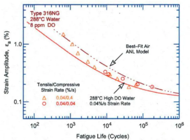
The fatigue rules used today in the nuclear industry were initially built and integrated into the ASME code in the 1960’s. Establishing fatigue rules is a challenge in itself since fatigue degradation depends on the wear of components which undergo repeated cycling: fatigue tests can therefore be very long and costly, if led on full-size components. As a result, the testing is in practice conducted on small laboratory specimens, which then triggers the question of how to extrapolate results to a full size component. Another difficulty is that the rules need to remain easy to apply in order to be applied for industrial engineering calculations. Since 2007, the USA with the NUREG/CR-6909 [1], have now included the evaluation of environmental effects in their official regulation. Indeed, on the curves presented in Figure 1 and Figure 2, the PWR water environment effect on the fatigue lifetime of material used in the manufacture of reactor components are illustrated.
Figure 1: Fatigue life of 304L steel in PWR water compared with the ANL model Air curve
Figure 2: Fatigue life of 316L steel in PWR water compared with the ANL model Air curve
The 304L and the 316L stainless steel are used for the manufacturing of the pressurized water reactors (PWR). Many components of this type of reactors are subjected to a multiaxial thermo-mechanical cycling [5] and [12]. Environmentally Assisted Fatigue is considered as one of the main mechanisms affecting the life of the PWR components
Based on more recent fatigue data (including tests at 300°C in air and PWR environment, etc…), some international codes (RCC-M, ASME and others) have proposed and suggested a modification of the austenitic stainless steels fatigue curve combined with a calculation of an environmental penalty factor, namely Fen, which has to be multiplied by the usual fatigue usage factor.
Unfortunately, there is no sufficient experimental data available concerning fatigue strength for the austenitic stainless steels subjected to structural loadings [6] [7] [8] [9] [10], which are used for power plants components. In order to obtain fatigue strength data under structural loading, biaxial test means with and without PWR environment were developed at LISN [11] [13] [14].
Two kinds of fatigue device have been developed. Within the same specimen geometry, structural loads can be applied in varying only the PWR environment.
The first device (FABIME2) is devoted to study the effect of biaxiality and mean strain/stress on the fatigue life. A second and new device based on FABIME2 is for the study of the impact of the environmental effect. With these
Hager DHAHRI et al. / Procedia Engineering 213 (2018) 571–580 573
Author name / Procedia Engineering 00 (2017) 000–000 3
new experimental results, we will study the effect of biaxiality and the PWR environment on the fatigue life of stainless austenitic steels.
2. The FIRST experimental device
The objective of this first fatigue test was to dissociate the effect of the mean stress and equibiaxial state loading. Indeed, we tried to obtain a negative load ratio in order to get the same results as the uniaxial data and eliminate the residual strain.
In this study, equibiaxial state loading generated from fatigue has been considered. It was used to optimize the geometry of a disk specimen refined in its center. It was used as a circumferentially embedded diaphragm with an applied pressure on both sides in order to obtain an equivalent strain in each loading direction in the plane (Figure 3).
Figure 3: Principle of the first fatigue test Figure 4: View of the spherical bending device: fatigue cell
The experimental device called « FABIME2» is divided into four parts: • Fatigue cell which contains the spherical bending specimen (cf. Figure 4), • Pressure generating system until 100 bars,
• Electrical enclosure,
• Homemade software developed under LABVIEW that provides control and acquisition data during the tests.
Two half-shells allow the positioning of the spherical bending specimen. Seal and embedment are realized by bolting these two parts.
Maximum experimental conditions are 100 bars for the pressure and 90°C for the temperature. An alternative differential pressure between the two sides of the spherical specimen is applied during the fatigue test.
To ensure well-defined experimental conditions, various measuring means are located symmetrically at the two half-shells
• Pressure sensor with a measuring range between 0 to 100 bars
• Type K thermocouple to measure the temperature of the fluid inside the fatigue cell
• Displacement sensor (LVDT) to measure the deflection at the center of the spherical bending specimen. This sensor has a 5mm range. Realizations of surface observations after the fatigue test show that the contact between LVDT and specimen is negligible (no fretting). No crack initiation is also observed directly under the LVDT.
• Two visualization windows on each half-shell, oriented at 45° with a diameter of 20 mm. The constitutive material is borosilicate glass with a permissible operating pressure of 100 bars.
574 Hager DHAHRI et al. / Procedia Engineering 213 (2018) 571–580
4 H.DHAHRI et al. / Procedia Engineering 00 (2017) 000–000
3. The experimental results [14]
Biaxial fatigue tests were carried out on two austenitic stainless steels: “316L THY”, and “304L CLI”. The first material has been provided by Thyssen Krupp Materials France as a 15mm thickness rolled sheet. The second material supplied by EDF is characterized by a thickness of 30 mm rolled sheet.
The first fatigue test campaign was performed on austenitic stainless steel type 316L. Five levels of deflection were studied: 1.6 / 1.4 / 1.2 / 1.1 and 0.9 mm.
In the frame of CEA-EDF-AREVA working group, a second fatigue test campaign was performed on austenitic stainless steel 304-CLI provided by EDF. This material completely agrees with the RCC-M and RCC-MRx [4] specification. Four levels of deflection were carried out 1.4 / 1.3 1.2 and 1.1 mm.
4. Interpretation of the experimental results
We present an interpretation of the equibiaxial fatigue tests with the definition of the equivalent strain used in the nuclear industry. This is an important step to evaluate the impact of an equibiaxial loading on the fatigue life. All tests performed in this study are carried out with imposed displacement (strain) with alternating load (without mean stress or strain), means with a stress ratio R=-1.
To compare the experimental data obtained from uniaxial and equibiaxial tests, it is necessary to define a total equivalent strain.
Two definitions of equivalent strain are proposed: the first is based on the definition of von Mises (used in the RCC-MRx) and the second on the definition of Tresca (used in the RCC-M, RSE-M).
Thus, the first equivalent strain used is the von Mises equivalent strain defined by the following equation:
. . 1
)
1
(
)
1
(
3
2
)
:
(
1
1
VM eq (1)with the strain deviatoric component:
)
(
3
1
.
tr
with ε1the principal strain and ν’ the “real” Poisson’s ratio (elastic ν=0.3 and plastic part ν=0.5).
The second equivalent strain is the Tresca equivalent strain defined by the following equation:
eqT
Max
i
j
1
1
(2)The proposal approach to determine the level of the equivalent strain for each FABIME2 test is as follows: • Determination of the value of the radial strain corresponding to the imposed deflection from the strain-deflection calibration curve [14]. With a similar mechanical behavior, the calibration curve can be used for the two materials.
• Determination of the von Mises or Tresca equivalent strain from the relation between the radial strain and the equivalent strain (von Mises or Tresca). This relation has been determined by elasto-plastic calculation of the fatigue test. Theses elastic-plastic behavior computations are used to determine the “real” value of the Poisson’s ratio by taking into account the elastic and plastic part. In our case, the Poisson’s ratio is 0.415 for the largest deflection test (±1.63 mm) and 0.396 for the lower deflection test (±0.9 mm).
Hager DHAHRI et al. / Procedia Engineering 213 (2018) 571–580 575
Author name / Procedia Engineering 00 (2017) 000–000 5
This method has been applied to the equi-biaxial fatigue tests presented earlier. The corresponding fatigue life curves are compared to that under uniaxial loading in Figure 5. It appears that there is no impact of equi-biaxial fatigue for the two types of materials, considering von Mises equivalent strains.
Figure 5: Fatigue data obtained on the two austenitic stainless steels (316L and 304L-CLI)
5. Specification of the new device FABIME2E
The second fatigue device (FABIME2E, E for environment) has been developed to apply on the same specimen geometry the same structural loads in varying only the PWR environment.
Compared to FABIME2, specification changes for FABIME2E device mainly focused on the following points: • Specimen is in contact with a PWR environment,
• An operating temperature of 340 °C, • A maximum pressure up to 350 bar,
• Monitoring and adjustment of dissolved hydrogen level during testing, • A perfectly flat and reproductive clamping of the specimen.
With these severe experimental conditions, four major technical difficulties had to be taken into account:
• The cohabitation of the PWR environment with the hydraulic oil at room temperature and 100 bar maximum,
• The PWR environment temperature stability: variations less than 1 °C up to several weeks should be allowed in order to detect the initiation of cracks,
• Monitor and adjust if necessary dissolved hydrogen level, • The perfect sealing of the device during the tests.
A double cylinder system has been proposed to separate PWR and hydraulic fluids to apply a mechanical solicitation to the specimen (Figure 6). A double acting cylinder would be moved by the hydraulic unit. Its movement would be mechanically transmitted (by the water incompressibility) to a primary cylinder to modify the
576 Hager DHAHRI et al. / Procedia Engineering 213 (2018) 571–580
6 H.DHAHRI et al. / Procedia Engineering 00 (2017) 000–000
volume of the PWR environment contained in each half-shell. Similarly to FABIME2 this system applies a differential pressure, up to 100 bars, to the specimen. The difference here is that the pressure variation around the specimen is between 150 and 350 bar, respectively the biphasic threshold of the PWR environment and the maximum pressure allowed by FABIME2E.
Figure 6: Double cylinder system for separation of PWR and Hydraulic fluid
If the required pressure in the PWR environment is obtained by its constraint thermal dilation, this phenomenon must be avoided during the test. A variation of 1 °C would cause a variation of several bars around the specimen. These pressure fluctuations may compromise the detection of the initiation of cracks by compliance. A stronger fluctuation could even lead the PWR environment under its biphasic threshold. This would require a test stop. To avoid this, a temperature regulation system with a great stability was required.
The evolution of the chemical composition of the environment was one of the concerns for this new bench. Hydrogen is the most volatile part of this, so the ability to measure and if necessary adjust its level was needed.
In the end, the requested instrumentation would enable the monitoring of the evolution of the following data, for each half-shell: temperature, pressure, displacement and dissolved hydrogen level.
6. The NEW experimental device: FABIME2E
The realization of FABIME2E was entrusted to French company TOP INDUSTRY. The maximum experimental conditions of the new device are 350 bar and 340 ° C.
The main organs of this new device are:
A cell consisting of two half shells for holding the specimen, A clamping system for the cell,
A sealing system compatible with the PWR environment, A closed PWR environment circuit,
A « double cylinder » system to apply the mechanical solicitations on the specimen, An accurate and reliable heating system,
A system for measuring and adjusting the level of dissolved hydrogen in the PWR environment, Instrumentation for temperature, pressure, displacement.
Hager DHAHRI et al. / Procedia Engineering 213 (2018) 571–580 577
Author name / Procedia Engineering 00 (2017) 000–000 7
Figure 7: View of the fatigue new bending device FABIME2E Figure 8: Comparison between FABIME2 and FABIME2E fatigue cells (same scale and specimen geometry)
Because of much higher pressures and temperatures, the FABIME2E cell has more imposing dimensions than its predecessor FABIME2 (
Figure 8). However, the specimen geometry remains absolutely identical to be usable indifferently on the both test benches.
7. Technical specifications
Each half- shell has the following instrumentation:
Two type K thermocouples, positioned at the top and bottom, A pressure sensor with a 0-400 bar range,
A LVDT compatible with the PWR environment, with a ± 5 mm range to measure the deflection of the specimen,
Two hydrogen sensors Pd -Ag from AREVA: one for measuring and one for adjusting the dissolved hydrogen level if necessary.
578 Hager DHAHRI et al. / Procedia Engineering 213 (2018) 571–580
8 H.DHAHRI et al. / Procedia Engineering 00 (2017) 000–000
Two metal rings are disposed on each side of the specimen to ensure the sealing of the cell during the test period. Clamping is achieved by means of a hydraulic clamp machine to ensure flatness, sealing and repeatability. Height heavy section attachment studs ensure the two half shells clamping around the specimen.
FABIME2E cell has a 100 ml volume. After filling the cell and high-pressure pipes the heating achieves the desired pressure because of the thwarted thermal dilation of the primary water.
Eight cartridge heaters with an output of 250W each are located on each half-shell to reach the nominal temperature of 340 ° C. The temperature rise is carried out at a maximum rate of 1 ° C / min. The maximum allowable temperature is 400 °C. Although the primary cylinder is at room temperature, a part of the pipes which connects it to each half-shell is also temperature controlled. Two EUROTHERM controllers (NANODAC model) ensure the regulation of the 4 heating zones.
The same hydraulic group provides oil to both FABIME2 and FABIME2E test benches.
As shown in Figure 6, a hydraulic cylinder allows transmitting loadings to the primary cylinder to deform the specimen.
As it is possible to do with the bench FABIME2, pressure, displacement or strain control is allowed. The development of the control software in the CEA laboratory allows great flexibility: cycling shape, holds, control mode modifications, mean pressure or strain.
The low-level tasks such as security management, hydraulic control and data reading require determinism and speed of processing. That is the reasons why they are devolved to real-time autonomous software running on a COMPACT RIO device (NATIONAL INSTRUMENT).
The tests management, acquisition and data analysis are performed by software running on a conventional PC. This second software controls each test sequence: from the filling of the PWR fluid till the crack initiation estimation through sending orders to the CRIO software and the EUROTHERM controllers.
8. First tests campaign (with high pressure and ambient temperature)
A first series of test was carried out with the FABIME2E device. One of the objectives of these tests was the validation of the concept of the stages separation (oil / primary water) via the intermediate cylinder. The second objective was to demonstrate the criterion for detecting a crack initiation in the center of the specimen.
This series consists of five tests. The experimental conditions are: an initial pressure of 175 bar, an ambient temperature (30 ° C.) and an imposed deflection of 1.3 mm and 1.2 mm. The principle of detection of fatigue crack initiation is achieved by studying the evolution of the pressure applied to the fluid via the intermediate cylinder to obtain the imposed deflection of 1.3mm or 1.2mm. When a "significant" change in this pressure is observed, the test is stopped, the test piece is take off and observed. The crack initiation criterion is defined as having a crack length of 5 mm at the surface (see Figure 9), which corresponds to a (downward) variation in the pressure of the order of 1 to 2 bar.
A test was carried out in an interrupted manner, once a crack initiation was detected, the specimen was subjected to 500 cycles and the evolution of the crack size was observed (see Figure 10).
Figure 9: View of the fatigue crack initiation when the pressure criterion is goal taken into account
Author name / Procedia Engineering 00 (2017) 000–000 9
Figure 10: Crack length evolution for FABIME2E tests (175 bar, T=30°C, Δf=1.3 mm)
Figure 11: Fatigue data (imposed deflection) obtained on the austenitic stainless steel (316L) with and without high pressure water environment
Hager DHAHRI et al. / Procedia Engineering 213 (2018) 571–580 579
Author name / Procedia Engineering 00 (2017) 000–000 9
Figure 10: Crack length evolution for FABIME2E tests (175 bar, T=30°C, Δf=1.3 mm)
Figure 11: Fatigue data (imposed deflection) obtained on the austenitic stainless steel (316L) with and without high pressure water environment
580 Hager DHAHRI et al. / Procedia Engineering 213 (2018) 571–580
10 H.DHAHRI et al. / Procedia Engineering 00 (2017) 000–000
Except the first test which devoted to validate the load-control home-made software. Four tests were carried out with a controlled deflection and the lifetime of all these tests under a pseudo-PWR environment (pressure water at 175 bar with ambient temperature 30°C) is divided by a factor of 2 compared to the same tests carried out on the FABIME2 device (in oil), see Figure 11.
9. CONCLUSION
This paper is focusing on the description of two kinds of experimental devices to perform fatigue tests on “structural” specimen with or without the effect of PWR environment.
The first device (FABIME2) is devoted to study the effect of biaxiality and mean strain/stress on the fatigue life. Biaxial fatigue tests are carried out on two austenitic stainless steels: 316L THY and 304L CLI. The results obtained show that The results obtained show that equi-biaxial loading have a low impact on the fatigue life, which is adequate with the design curve defined and used in the codification.
A second and new device based on FABIME2 is under development for the study of the impact of the environmental effect. This device will study the impact of the equibiaxial loadings with a primary water environment PWR (300°C with a permanent pressure of 140 bars). The first experimental tests validate the concept of this device (FABIME2E).
Acknowledgements
F. Datcharry and M. Rousseau from CEA is very greatly acknowledged for his participation in the FABIME2E conception.
References
[1] Chopra O.K. and Shack W.J. (2007), NUREG/CR-6909, Rev. 0, “Effect of LWR Coolant Environments on the Fatigue Life of Reactor Materials,”.
[2] RCC-M (2007) – Design and Construction Rules for mechanical components of nuclear PWR islands – 2007 edition with addenda in 2008, 2009 and 2010.
[3] EN-13445-3 V1 standard (2014), “Unfired pressure vessels – Part 3: Design,”.
[4] RCC-MRx (2012) « Règles de Conception et de Construction des Matériels Mécaniques des Installations Nucléaires applicables aux structures à haute température et à l'enceinte à vide ITER », AFCEN Code, Association Française pour les Règles de Conception et de Construction des chaudières Électronucléaires. www.afcen.com.
[5] Fissolo A. et al. (2009), "Crack Initiation under thermal fatigue: an overview of CEA experience, Part 1: thermal fatigue appears to be more damaging than uniaxial isothermal fatigue", Int. Journal of Fatigue, vol.31(3), p.587-600.
[6] Lefebvre D.F. (1989), “Hydrostatic Pressure effect on Life Prediction in Biaxial Low-cycle fatigue”, Biaxial and Multiaxial Fatigue, EGF 3. [7] Itoh T., Sakane M. and al. (2006)," A design procedure for assessing low cycle fatigue life under proportional and non-proportional loading",
Int. Journal of Fatigue, 28.
[8] Parsons, M. W. Et Pascoe, K. J. (1975), "Development of a biaxial fatigue testing rig", Journal of Strain Analysis, 10, N° 1, p1-3.
[9] Shimada H., Shimizu K., Obata M., Chikugo K. & Chiba, M. (1976), "A new biaxiaI testing machine for the flat specimen and a fundamental study on the shape of the specimen", Technology Reports, Tohoku Univ., 42. N° 2, p351-369.
[10] Poncelet M. et al. (2010), "Biaxial High Cycle Fatigue of a type 304L stainless steel: Cyclic strains and crack initiation detection by digital image correlation", European Journal of Mechanics A/Solids.
[11] Bradai S. et al. (2013), PVP2013-97200, “Crack Initiation under Equibiaxial Fatigue, Development of a particular Equibiaxial Fatigue Device.”
[12] De Baglion L. (2006), « Comportement et endommagement en fatigue oligocyclique d’un acier inoxydable austénitique 304L en fonction de l’environnement (vide, air, eau primaire REP) à 300°C », Thèse de l’Ecole Nationale Supérieure de Mécanique et d’Aérotechnique.
[13] Bradaï S., Gourdin C. and Gardin C. (2014), “Study of crack propagation under fatigue equibiaxial loading”, PVP2014-28417, ASME PVP. [14] Bradaï S., Gourdin C. and al. (2015), “Equi-Biaxial Loading Effect on Austenitic Stainless Steel Fatigue Life”, PVP2015-45293, ASME