Structural Engineering and Mechanics, Vol. 57, No. 2 (2016) 000-000
DOI: http://dx.doi.org/10.12989/sem.2016.57.2.000 000
Copyright © 2016 Techno-Press, Ltd.
http://www.techno-press.org/?journal=sem&subpage=8 ISSN: 1225-4568 (Print), 1598-6217 (Online)
Effect of stacking sequence of the bonded composite patch
on repair performance
Hadja Imane Beloufa
1, Djamel Ouinas
1, Mostapha Tarfaoui
2and Noureddine Benderdouche
31
Laboratoire de Modélisation Numérique et Expérimentale des Phénomènes Mécaniques, Faculty of Sciences and Technology, University Abdelhamid Ibn Badis of Mostaganem, 27000, Algeria
2
Laboratoire Brestois de Mécanique et des Systèmes, ENSTA Bretagne, 2 Rue François Verny, 29806 Brest Cedex 9, France
3
SEA2M, Faculty of Sciences and Technology, University Abdelhamid Ibn Badis of Mostaganem, 27000, Algeria
(Received October 5, 2015, Revised December 16, 2015, Accepted December 24, 2015)
Abstract.
In this study, the three-dimensional finite element method is used to determine the stress
intensity factor in Mode I and Mixed mode of a centered crack in an aluminum specimen repaired by a composite patch using contour integral. Various mesh densities were used to achieve convergence of the results. The effect of adhesive joint thickness, patch thickness, patch-specimen interface and layer sequence on the SIF was highlighted. The results obtained show that the patch-specimen contact surface is the best indicator of the deceleration of crack propagation, and hence of SIF reduction. Thus, the reduction in rigidity of the patch especially at adhesive layer-patch interface, allows the lowering of shear and normal stresses in the adhesive joint. The choice of the orientation of the adhesive layer-patch contact is important in the evolution of the shear and peel stresses. The patch will be more beneficial and effective while using the cross-layer on the contact surface.
Keywords: composite bonded patch; sequence of ply; adjacent cross-layer; contact surface of repair; stress
intensity factor (SIF); finite element analysis
1. Introduction
The composite patches are used in the aeronautics industry for the repair of damaged metallic structures or restoration of weakened structures capacity. Repairing cracks by single or double sided bonding with composite material patch, has proved efficient in reducing the stress intensity factor (SIF) at the crack tip with several advantages including improved fatigue behavior, enhanced resistance to corrosion and wear, ease of fabrication and good performance. That
Corresponding author, Professor, E-mail: [email protected]
aPh.D. Student, E-mail: [email protected]
bProfessor, E-mail: [email protected]
Hadja Imane Beloufa, Djamel Ouinas, Mostapha Tarfaoui and Noureddine Benderdouche
ultimately leads to longer life time of the damaged structure (Baker et al. 1988, Atluri 1997, Rose 1982, Chow et al. 1997, Lena et al. 1998, Ouinas et al. 2003). Baker addressed the problem of maintenance of military aircraft by proposing the alternative of using composite patches to repair damaged parts (Baker 1997, Baker et al. 1993). In this case, the composite patch will help to tightly bridge the cracked area. The use of numerical methods, especially the finite element method, has significantly contributed to the understanding of the mechanical behavior of the damaged structures after repair with a composite patch. The finite element calculation method is known to give a sufficiently accurate estimation of SIF at crack-tips. It was used to determine the SIF of a crack repaired with a single and double patch (Bachir Bouiadjra et al. 2010a, b, Albedah
et al. 2011, Mhamdia et al. 2011, Bachir Bouiadjra et al. 2002).
Ouinas et al. (2007, 2009) have shown the effect of the composite material of the patch on the amplification of the stress concentration at notch root extremities, and also on the SIF at the crack-tips. Chung et al. (2000) evaluated the safety of cracked aluminum plate repaired with boron/epoxy patch while optimizing the geometrical configuration of the patch. Ratwani (1978) observed experimentally that there is a big difference from the crack propagation rates between thin and thick repaired panels. Denney et al. (1997) conducted a series of experiments to study the effect of the location and geometry of the bonding area on the fatigue behavior of thin aluminum panels cracked and repaired with a composite patch. The influence of the fiber orientation of the composite material of the semi-circular patch on the SIF of a specimen subjected to tensile stress and containing a through crack in the edge, in the presence of Full Width Disbond (FWD) at the crack-tip was highlighted by Ouinas et al. (2010a, b).
They showed that the reduction of the SIF increases with increasing the thickness of the patch for disbond height greater than crack size. An opposite behavior occurs when the crack length exceeds the height of FW-disbond. Moreover, when the height of FW-disbond exceeds the length of the crack, the SIF reduction exceeds 50% for patch with greater than 1 mm (Ouinas et al. 2012, Bachir Bouiadjra et al. 2012) analyzed the effect of the separation on the performance of the composite patch repair in aircraft structures. They showed that the presence of the adhesive disbond increases the stress intensity at the crack tips reducing the effectiveness of the repair.
The optimization of the shape of the patch has been investigated by Mhamdia et al. (2012). They showed that the arrow patch reduces both the SIF at the crack-tip and the adhesive stresses, which consequently improves the efficiency of the repair and its durability. Gu et al. (2011) studied the mechanical behavior of Al7075-T6 plate containing a V-notch repaired with a patch composite. They found that the SIF of the notched plate is reduced by a factor of 1/6 to1/20 upon a repair by using a bonded composite patch. Albedah et al. (2010) estimated the SIF by FEM of a repaired crack using single and double circular patch by comparing the weight gain. Srilakshmi et
al. (2014) have experimentally studied the behavior of an aluminum plate containing an inclined
crack repaired with a single and double-sided composite patch using digital image correlation technique. They estimated the shear strain distribution in the adhesive layer. Ramji et al. (2013) compared five different forms of patch including circular, rectangular, square, elliptical and octagonal for repairing an inclined crack. They suggested that a patch having an octagonal shape and extended to a maximum area is recommended for the repair of a panel containing an inclined crack. The genetic algorithm in conjunction with the finite element method has been used successfully by Kashfuddoja et al. (2012) for the optimization of patch geometry and adhesive layer thickness in order to increase repair performance. The repair patch considered for the present investigation is made of boron/epoxy. It is frequently used with great success by many researchers (Bachir Bouiadjra et al. 2008, Chalkley et al. 2003, Tay et al. 1996, Baker 1997, Ramji et al.
Effect of stacking sequence of the bonded composite patch on repair performance
Table 1 Mechanical properties of materials
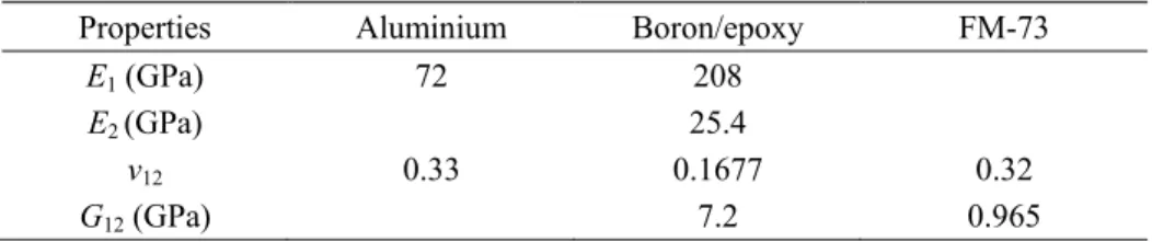
Properties Aluminium Boron/epoxy FM-73
E1 (GPa) 72 208
E2 (GPa) 25.4
ν12 0.33 0.1677 0.32
G12 (GPa) 7.2 0.965
2012).
The objective of this study is to analyze the behavior of a centered crack with and without the reinforcement by a composite patch of aluminum specimen in mode I and mixed mode using 3D finite element method. The method of contour integral was used to evaluate SIF at the crack-tips as repaired by a composite patch. The effects of adhesive layer thickness FM73 and the composite patch on the variation of SIF of the repaired structure are examined. The effects of the orientation of the sequences of the stacking plies, of the specimen-patch contact surface, the peel stresses in the adhesive layer and the shear stresses in the patch are studied. The constitution of the sequence plies of the composite patch in contact with the crack makes the originality of this work.
2. Finite element model
In this modeling, a thin aluminum specimen having the following dimensions: length H=200
mm, width W=20 mm and thickness ep=1 mm is considered. We assume the existence of a crack in
the middle of the specimen and perpendicular to the loading plan. The aluminum specimen is subjected to a uniaxial uniform tension in the vertical direction under the applied stress amplitude
σ=100 MPa, in one end, while the other end is clamped (0 degrees of freedom). This is to simulate
the specimens in the experimental conditions. The crack is repaired with a composite patch of boron/epoxy whose dimensions are: a variable height h, a fixed width w=20 mm, and a variable
thickness eR. The thickness of the layers constituting the patch is the same and equal to 0.125 mm.
Note that a good adhesion is obtained only when the thickness is within the range of 0.125-0.25 mm (Chukwujekwu et al. 2005). For this study the adhesive thickness is selected as 0.127 mm, which is sufficient to transfer the load from the metallic specimen to the composite patch. The
properties of the adhesive layer FM73 are: a shear modulus Ga=965 MPa and a thickness ea=0.127
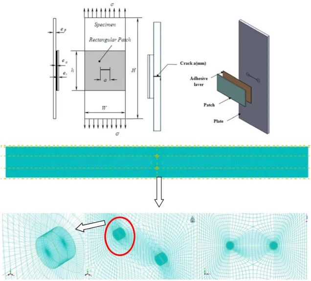
mm. The mechanical properties of the assembly of materials are given in Table 1. Fig. 1 shows the geometrical model of the repaired structure. To perform the analysis, we used the code of nonlinear finite element ABAQUS/CAE 6.14-2 (2014), developed by SIMULIA commercial Inc. The contour integral method was used to determine SIF at the crack-tips. Various mesh densities were used until convergence of the results was achieved. The specimen was meshed using 8924 hexahedral-dominated quadrilateral elements with reduced integration in three dimensions and 59636 nodes of type C3D20R. In the presence of the central crack, the number of quadrilateral elements increases by increasing the size of the crack. A refined meshing in the vicinity of the crack was carried out to simulate high stress gradients (Fig. 1). The finite element used for the adhesive is identical to that of the specimen. The results of SIF are compared by a patch of identical size in hexahedral-dominated solid elements with reduced integration.
Fig. (b) B 3. Stu We hexahe refined adequa meshin crack l the con For In differe Hadja Iman 1 Geometrica Bonded patch udy of conv e modeled th edral brick e d in the vici acy of the m ng. Fig. 2 sh lengths, with nvergence of r large crack addition we ent thickness ne Beloufa, Dj al model and on crack vergence he overall s lements dom inity of the mesh, we ma hows the effe h and withou f the SIF at a lengths a mi e have also to reinforce jamel Ouinas, mesh of struc structure (th minated from crack. The de use of di ect of the num ut repair patc and beyond 4 inimum of 30 tested the c e the cracked , Mostapha Ta cture (plate an he specimen, m Type C3D2 material be ifferent grids mber of finit ch. Note that 4000 element 000 element convergence d specimen w Tarfaoui and N nd patch) (a) C , the patch 20R with redu ehavior is el s to test the te elements o increasing t ts provided t s are necessa of our me with aluminum Noureddine Be Cracked speci
and the adh uced integrat lastic and lin speed and th on the value the number o
hat the crack ary to reach c sh with a c m alloy. Sev enderdouche imen in the m hesive joint) tion. The me near. For th he reliability of SIF for d of elements l k length is sm convergence composite pa veral crack si middle ) using esh was he good y of the different leads to mall. . atch of izes are
Effect of stacking sequence of the bonded composite patch on repair performance
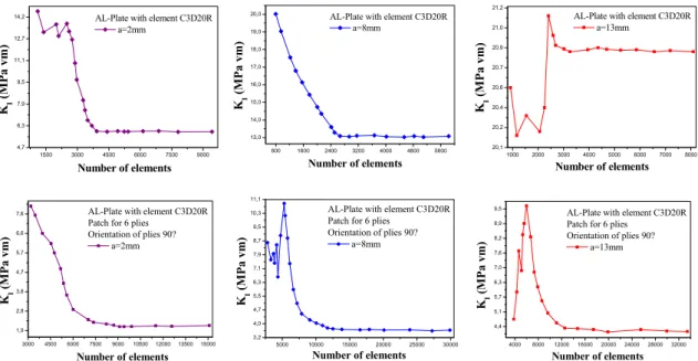
Fig. 2 Effect of number of solid elements (C3D20R) on the mesh convergence Table 2 Comparison of SIF for unrepaired crack (a=8 mm)
Feddersen (1996) MEF-C3D20R a (mm) KI (MPa√m) KI (MPa√m) 2 5.59 5.23 3 6.86 6.79 4 7.90 7.89 5 8.86 8.93 6 9.70 9.84 7 10.48 10.84 8 11.20 11.89 9 11.88 12.54 10 12.53 13.68 11 13.14 14.25 12 13.72 15.64 13 14.28 18.18 14 14.82 20.27 15 15.34 22.92 16 15.85 26.43
considered. The calculation revealed that for short crack lengths the convergence is reached at 9000 elements. The increase in crack length requires a larger number of elements. For this purpose, the convergence is reached at 12000 elements, whatever the number of plies of the composite patch. The results of the finite elements are compared with the mathematical model of
1500 3000 4500 6000 7500 9000 4,7 6,3 7,9 9,5 11,1 12,7 14,2 Number of elements KI (MP a vm)
AL-Plate with element C3D20R a=2mm 800 1600 2400 3200 4000 4800 5600 13,0 14,0 15,0 16,0 17,0 18,0 19,0 20,0 Number of elements KI ( MPa vm )
AL-Plate with element C3D20R a=8mm 1000 2000 3000 4000 5000 6000 7000 8000 20,1 20,2 20,4 20,6 20,7 20,9 21,0 21,2 Number of elements KI ( MP a v m )
AL-Plate with element C3D20R a=13mm 3000 4500 6000 7500 9000 10500 12000 13500 15000 1,9 2,8 3,8 4,7 5,7 6,6 7,6 Number of elements KI (M P a vm )
AL-Plate with element C3D20R Patch for 6 plies
Orientation of plies 90? a=2mm KI (M P a vm ) 5000 10000 15000 20000 25000 30000 3,2 4,0 4,7 5,5 6,3 7,1 7,9 8,7 9,5 10,3 11,1 Number of elements AL-Plate with element C3D20R Patch for 6 plies
Orientation of plies 90? a=8mm 4000 8000 12000 16000 20000 24000 28000 32000 4,4 5,1 5,7 6,3 7,0 7,6 8,2 8,9 9,5 Number of elements KI (M P a vm )
AL-Plate with element C3D20R Patch for 6 plies
Orientation of plies 90? a=13mm
Hadja Imane Beloufa, Djamel Ouinas, Mostapha Tarfaoui and Noureddine Benderdouche
Fig. 3 Variation of SIF vs. crack length in mode I.
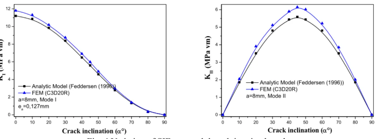
Fig. 4 Variation of SIF vs. crack length in mixed mode
the infinite plate (see Table 2). Fig. 3 compares the evolution of the SIF as a function of length of the centered crack. The SIF of a central crack in an infinite plate subjected to an axial load is given by (Feddersen 1996) b a a KI 2 sec (1)
Where σ is the applied stress, a is half the central crack length and b is half the width of the plate. It is noteworthy that the SIF increases exponentially with the increase in the size of the crack. When the crack length is less than 8 mm no difference was noticed between the results of the finite elements and those of the analytical model. When a=8 mm, the error reaches 5.2% compared with the solid elements (C3D20R). This is due to the analytical model that defines an infinite plate with a crack/width ratio away from one. For a larger crack size, the divergence of results becomes more and more important and reaches 40%.
In regard to mixed mode, we performed a comparison between the values obtained by the finite element method and the analytical model given by Smith (1988)
asin2 KI (2) 2 3 4 5 6 7 8 9 10 11 12 13 14 15 16 6 8 10 12 14 16 18 20 22 24 26 28 Crack length a (mm) KI ( MP a vm)
Analytic Model (Feddersen (1996)) FEM (C3D20R) a:variable, Mode I ea=0,127mm 0 10 20 30 40 50 60 70 80 90 0 2 4 6 8 10 12 Crack inclination (°) KI ( MP a vm )
Analytic Model (Feddersen (1996)) FEM (C3D20R) a=8mm, Mode I ea=0,127mm 0 10 20 30 40 50 60 70 80 90 0 1 2 3 4 5 6 Crack inclination (°) KII ( MP a vm )
Analytic Model (Feddersen (1996)) FEM (C3D20R)
Effect of stacking sequence of the bonded composite patch on repair performance
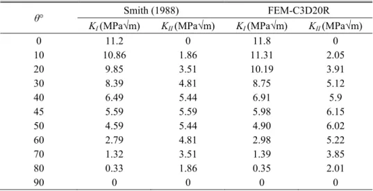
Table 3 Comparison of SIF for unrepaired inclined crack (a=8 mm)
θ° Smith (1988) FEM-C3D20R
KI (MPa√m) KII (MPa√m) KI (MPa√m) KII (MPa√m)
0 11.2 0 11.8 0 10 10.86 1.86 11.31 2.05 20 9.85 3.51 10.19 3.91 30 8.39 4.81 8.75 5.12 40 6.49 5.44 6.91 5.9 45 5.59 5.59 5.98 6.15 50 4.59 5.44 4.90 6.02 60 2.79 4.81 2.98 5.22 70 1.32 3.51 1.39 3.85 80 0.33 1.86 0.35 2.01 90 0 0 0 0 asin cos KII (3)
Fig. 4 and Table 3 illustrate the comparison of the SIF of an unrepaired inclined crack (a=8 mm). Figs. 4 (a), (b) show the variation of the SIF in mode I as a function of the inclination of the crack. The SIF decreases with the increase of the inclination angle of the crack until the angle 90°. The maximum values are recorded for the orientation of the crack perpendicular to the applied load. Passing from mode I at 0° to mode II at 45° results in halving SIF values.
The maximum values of SIF KII mode II are obtained when the crack is inclined at 45°,
producing a maximum shear. In both cases (mode I and mode II), the values obtained by the analytical model are low compared to the values of the finite element method. The maximum error between the analytical model and the FEM at α=0° is in the order of 5% and 0% by modes I and II, respectively, for a fixed crack length a=8 mm.
4. Effect of the patch height versus layer orientation
The parameters of the fracture are influenced by the patch rigidity, the area of the specimen-patch contact area and the adhesive strength (Ouinas et al. 2007, 2009). To highlight the process of repair of a centered crack, the aluminum specimen was repaired with a composite patch. The analysis consists in varying the length of the repaired crack while maintaining the same mechanical characteristics of both the specimen and the patch.
We show in Fig. 5 the variation of SIF as a function of crack length as reinforced by a patch of 40 mm in height. Different orientations of the patch layers (θ=0°, 45° and 90°) are considered. The effect of the number of plies is evidenced by considering four combinations of layers 6, 12, 24 and 32. The SIF was found to increase with increasing the length of the unrepaired crack. The SIF value of a crack having a size of 16 mm is 80% higher compared to that of a 2 mm crack. Furthermore, when the number of plies is considered, the SIF of the repaired crack is continuously reduced with the increased number of plies in the patch. The greatest reduction is obtained by a patch in which the plies are oriented at 90°.
Hadja Imane Beloufa, Djamel Ouinas, Mostapha Tarfaoui and Noureddine Benderdouche
Fig. 5 Evolution of SIF vs. crack size (case h=40 mm)
Fig. 6 Evolution of KRI vs. crack size (case h=40 mm)
2 3 4 5 6 7 8 9 10 11 12 13 14 15 16 3 6 9 12 15 18 21 24 27 30 KI ( M P a m ) a (mm)
Patch for 6 plies Without patch Height of patch h=40 mm Orientation of plies =0° =45° =90° 2 3 4 5 6 7 8 9 10 11 12 13 14 15 16 3 6 9 12 15 18 21 24 27 30 KI ( MP a m )
Patch for 12 plies Without patch Height of patch h=40 mm Orientation of plies =0° =45° =90° a (mm) 2 3 4 5 6 7 8 9 10 11 12 13 14 15 16 3 6 9 12 15 18 21 24 27 30 KI ( M P a m )
Patch for 24 plies Without patch Height of patch h=40 mm Orientation of plies =0° =45° =90° a (mm) 2 3 4 5 6 7 8 9 10 11 12 13 14 15 16 3 6 9 12 15 18 21 24 27 30 KI ( MPa m )
Patch for 32 plies Without patch Height of patch h=40 mm Orientation of plies =0° =45° =90° a (mm) 2 3 4 5 6 7 8 9 10 11 12 13 14 15 16 35 40 45 50 55 60 65 70 75 80 85 90 95 100 KRI (%)
Patch for 12 plies Height of Patch h=40mm a (mm) Orientation of plies =0° =45° =90° 2 3 4 5 6 7 8 9 10 11 12 13 14 15 16 55 60 65 70 75 80 85 90 95 KRI ( % )
Patch for 32 plies Height of Patch h=40mm a (mm) Orientation of plies =0° =45° =90° 2 3 4 5 6 7 8 9 10 11 12 13 14 15 16 50 55 60 65 70 75 80 85 90 95 KRI (%)
Patch for 24 plies Height of Patch h=40mm a (mm) Orientation of plies =0° =45° =90° 2 3 4 5 6 7 8 9 10 11 12 13 14 15 16 20 25 30 35 40 45 50 55 60 65 70 75 80 85 90 95 KRI (%) a (mm) Orientation of plies =0° =45° =90°
Patch for 6 plies height of Patch h=40mm
Effect of stacking sequence of the bonded composite patch on repair performance
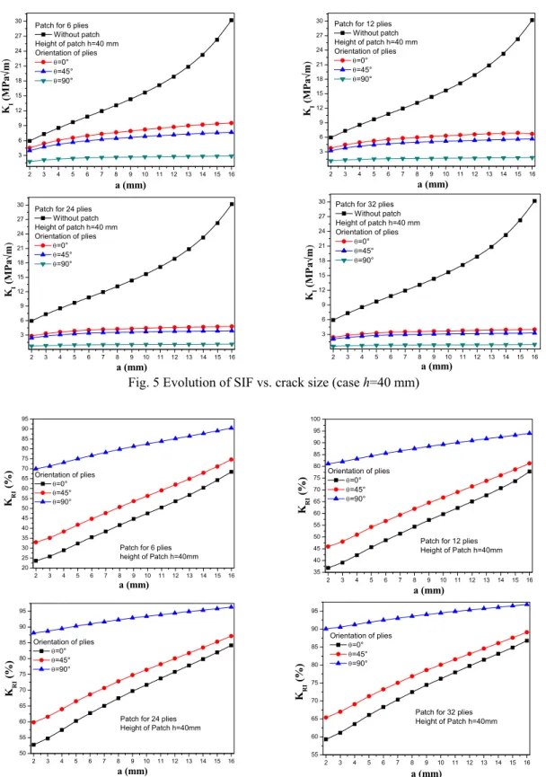
For a better visualization of the SIF data of a repaired crack, we introduced the evolution of the reduction of SIF with respect to the crack length for different sequences of patch plies (Fig. 6). This reduction is defined by the following parameter (Ouinas et al. 2012)
nrep rep RI K K K 1 (4)
Where Krepand Knrep are the SIF of the crack with and without patch, respectively.
The reduction of the SIF of the crack of 2 mm size repaired by a patch having 6 plies and a height of 40 mm, attained the order of 25% and 32% when the orientation angles are fixed at 0° and 45°, respectively. It evolves from single to double for an orientation of the plies of 90°.
Note also that the reduction of the SIF increases linearly with increasing the crack length. Whatever the number of plies, the maximum reduction of SIF reached 65% when the size of the crack is eight times more. This reduction will be greater with the importance of the geometric width/crack ratio (W/a). The significant stiffness of the composite patch, the folds of which are oriented parallel to the applied load, reduced maximally and proportionally the SIF. The reduction is almost stable with the increasing number of plies when the orientation angle is 90°.
The 6-ply patch reduces the SIF by 70% when fiber orientation is perpendicular to propagating crack direction. The largest reduction is greater than 90% when using a unidirectional patch of 32 plies whatever the size of the repaired crack. Increasing the ply number in the patch significantly reduces the SIF and also increases the cost. It is thus necessary to take into account the feasibility of applying a thick patch and also its cost.
5. Influence of adhesive thickness
The adhesive often represents the weak part of the reinforcement when high levels of stress are applied. This may result in premature failures of the reinforced or the repaired structures (Ouinas
et al. 2012). Indeed, the fracture or debonding of the adhesive causes the detachment of the
reinforcement.
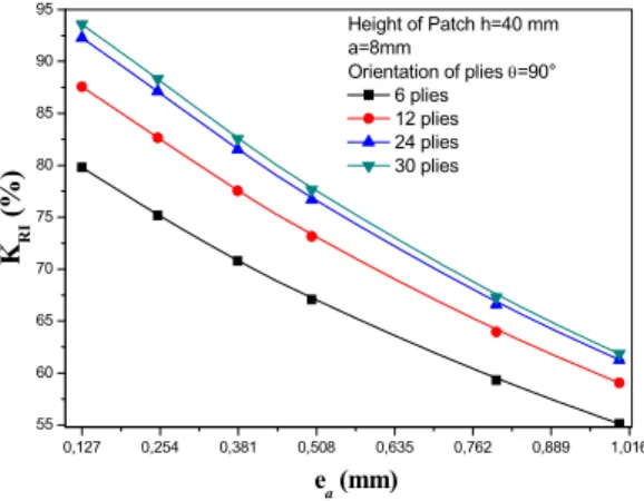
Furthermore, the effect of the thickness of the adhesive plays also an important role in the
Fig. 7 Effect of adhesive thickness layer on the KRI
0,127 0,254 0,381 0,508 0,635 0,762 0,889 1,016 55 60 65 70 75 80 85 90 95 KRI ( %) ea (mm) Height of Patch h=40 mm a=8mm Orientation of plies =90° 6 plies 12 plies 24 plies 30 plies
Hadja Imane Beloufa, Djamel Ouinas, Mostapha Tarfaoui and Noureddine Benderdouche
Fig. 8 Effect of composite patch thickness layer on KRI
transmission of stresses from the cracked specimen to the composite patch. Comparing the reduction of SIF as a function of the crack length having different patch thicknesses with respect to the adhesive joint used is shown in Fig. 7. The figure reveals that decreasing the thickness of the adhesive decreases the value of the SIF. That clearly suggests that a thin adhesive layer is appropriate to repair damaged structures. Thicker layers increase the adhesion but substantially reduce the absorptive capacity of the stress field by the patch. For example, a height of patch of 40 mm with plies oriented perpendicular to the crack propagation direction causes a SIF reduction of the order of 30% when the thickness of the adhesive layer is increased from 0.127 mm to 1 mm
whatever the plies number (crack size a=8 mm). The KRI factor of a 6- ply unidirectional patch
oriented at 90°, bonded on a crack size a of 8 mm with an adhesive layer thickness ea of 0.127
mm; reached 80% with a patch height of 40 mm.
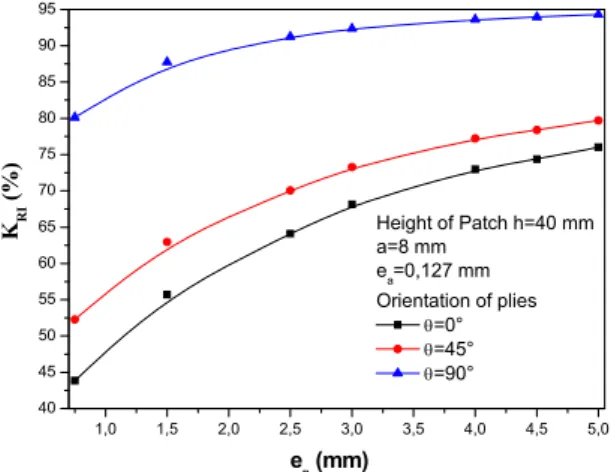
6. Effect of patch thickness
Fig. 8 illustrates the effect of the patch thickness on the reduction of the stress intensities with respect to crack length. The thickness of the adhesive layer is kept as 0.127 mm. It is evident that thickening the patch proportionally reduces the SIF values at the crack tips. The most significant
reduction is visible below a thickness of 3 mm. Beyond that, the KRI is negligible. The
unidirectional patch having plies oriented at 90°, exhibits the best absorption of the stresses transferred by the adhesive layer over the plastically deformed zone of the crack.
It is noteworthy that the maximum reduction of a patch having a height of 40 mm and an orientation of the plies at 90°, attains 80% for a crack size of 8 mm. This reduction increases with increasing the height of the patch. When the plies are oriented at 90° the maximum reduction achieved is about 35% and 48%, with respect to those oriented at 0° and 45°. This confirms that the choice of thick patch improves the performance of the structure. The reduction rate of SIF depends not only on the patch thickness but also on its nature (Ouinas et al. 2007). Finally, it is preferable to use a composite patch that contains multiple plies to repair damaged structures. The sequence of the plies must be carefully optimized.
1,0 1,5 2,0 2,5 3,0 3,5 4,0 4,5 5,0 40 45 50 55 60 65 70 75 80 85 90 95 KRI ( %) ep (mm) Height of Patch h=40 mm a=8 mm ea=0,127 mm Orientation of plies =0° =45° =90°
Effect of stacking sequence of the bonded composite patch on repair performance
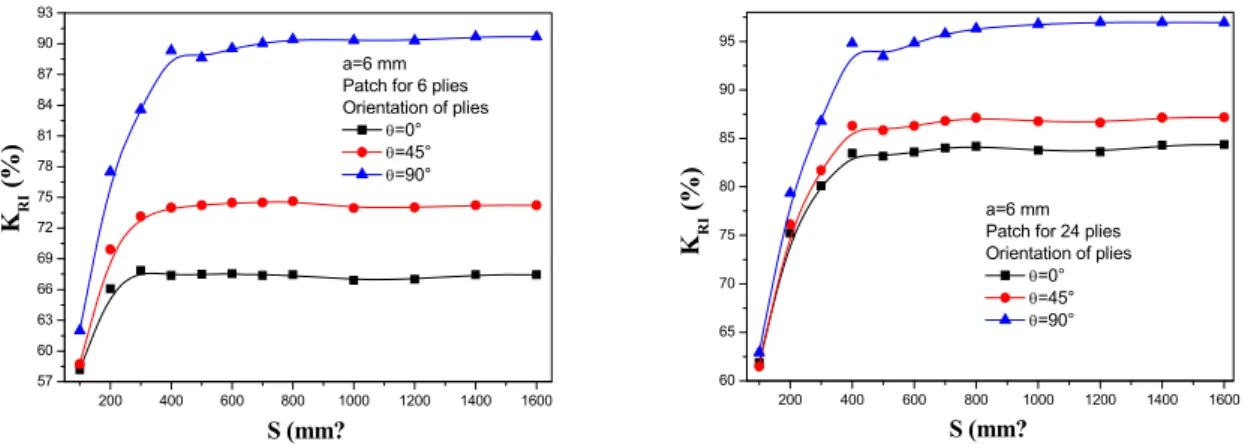
Fig. 9 Evolution of KRI vs. patch-specimen contact surface
7. Effect of patch-specimen contact surface
We show in Fig. 9 the variation of the reduction of the SIF as a function of the patch-specimen contact surface for three different ply orientations. The repaired crack length was fixed at 16 mm but two different patch thicknesses were used (6 and 24-plies). The reduction has almost saturated beyond a contact surface S of 400 mm² (h=20 mm). Therefore, the increase of the contact surface has no significant effect on the SIF reduction in contrast to the effect of the number of plies. The maximum reduction of 90% and 95% is obtained for a laminate patch of, respectively, 6-ply and 24-ply oriented at 90°. The SIF reduction between the two cases is rather small (5%) whereas the loss of the material is 4 times larger, which requires a cost optimization.
8. Variation of stress in the adhesive layer
The composite bonded assemblies are increasingly used in the automotive and aerospace industries. The mechanical behavior of the patched structure is rather limited compared to that of the adhesive. The latter plays a crucial role in bonding a patch to the structure and enhances the load transfer to the patch. The efficiency of the bonding depends largely of the extent of the adhesive shear modulus. But larger shear moduli also cause higher shear stresses in the bonded assembly which results in premature failure of adhesion (delamination or fracture) (Ouinas et al. 2007). One major problem associated to their use is the heterogeneity of the stress distribution in the adhesive layer. It is thus judicious to determine the distribution of shear stresses τyz in the
adhesive layer along the vertical line. In Fig. 10 we illustrate the influence of both the thickness and orientation of the plies of the composite patch as a function of the shear stress distribution on the adhesive layer. Note that the shear stresses are antisymetrical with respect to either side of the
repaired crack. Thus, τyz stresses reach significant peaks in the vicinity of the crack reinforced by a
composite patch having 6 plies. By increasing the number of patch plies by 4 times, the maximum shear stresses are transferred from the crack toward the ends of the adhesive layer. The increased number of patch layers causes increased shear stress at the overlap of the patch.
200 400 600 800 1000 1200 1400 1600 60 65 70 75 80 85 90 95 KRI ( %) a=6 mm
Patch for 24 plies Orientation of plies =0° =45° =90° S (mm? 200 400 600 800 1000 1200 1400 1600 57 60 63 66 69 72 75 78 81 84 87 90 93 S (mm? KRI ( %) a=6 mm Patch for 6 plies Orientation of plies
=0° =45° =90°
Hadja Imane Beloufa, Djamel Ouinas, Mostapha Tarfaoui and Noureddine Benderdouche
Fig. 10 Effect of patch thickness on the peel stress in the adhesive layer for different ply orientation
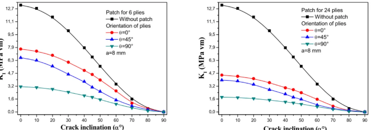
Fig. 11 Comparison of the SIF mode I of an inclined, repaired and unrepaired, crack for different composite patch thickness values (a=8 mm)
Therefore, the rigidity of the patch is directly related to the localization of the damage initiation in the structure to be repaired. Indeed, in the case of a reinforcement by a thin patch the stress concentration at the crack cannot be relieved by bonding and the most loaded area remains around the crack. In contrast when using a sufficiently thick patch the stress concentration zone occurs at the ends. Indeed, the maximum stresses are precisely located at the patch overlap edges. Therefore, the stress distribution in the adhesive governs the rupture of the peel-reinforced structure at the contour of the crack or at the overlap patch edges. The shear stresses are minimal for the lowest orientation of the patch plies independent of their thickness or the size of the repaired crack considered. It is thus preferable to use low orientation of plies in contact with the bond as long as shear stresses are not affected by such orientations.
9. Stress intensity factor in mixed mode
Figs. 11 and 12 represent the variation of KI and KII as a function of the inclination of the
repaired and unrepaired crack for four different thicknesses of composite patch having the same
0,0 0,1 0,2 0,3 0,4 0,5 0,6 0,7 0,8 0,9 1,0 -12 -9 -6 -3 0 3 6 9 12 yz (MP a) h/hp
Patch for 6 plies Orientation of plies =0° =45° =90° ea=0,127 mm, Ga=965 MPa a=8 mm 0,0 0,1 0,2 0,3 0,4 0,5 0,6 0,7 0,8 0,9 1,0 -15 -12 -9 -6 -3 0 3 6 9 12 15 yz (M P a) h/hp
Patch for 24 plies Orientation of plies =0° =45° =90° ea=0,127 mm, Ga=965 MPa a=8 mm 0 10 20 30 40 50 60 70 80 90 0,0 1,6 3,2 4,7 6,3 7,9 9,5 11,1 12,7 KI ( M P a vm) Crack inclination (°)
Patch for 6 plies Without patch Orientation of plies =0° =45° =90° a=8 mm 0 10 20 30 40 50 60 70 80 90 0,0 1,6 3,2 4,7 6,3 7,9 9,5 11,1 12,7 KI ( M P a vm) Crack inclination (°)
Patch for 24 plies Without patch Orientation of plies =0° =45° =90° a=8 mm
Effect of stacking sequence of the bonded composite patch on repair performance
Fig. 12 Comparison of the SIF mode II of an inclined, repaired and unrepaired, crack for different composite patch thickness values (a=8 mm)
Fig. 13 Evolution of KRI vs. crack inclination
height of 40 mm. KI decreases with increasing the angle of inclination whatever the patch
thickness (Fig. 11). It reaches its maximum value when the crack is oriented perpendicular to the loading. For a crack of 8 mm repaired with 6-ply patch, values of 7.9 MPa and 3.2 MPa are found when the orientation angles are 0° and 90°, respectively (Fig. 11). The increase in the crack
orientation angle causes a gradual decrease of KI. It reaches zero when the crack is oriented parallel
to the loading axis.
In contrast, KII reaches its maximum when the crack is oriented at 45° relative to the axis of
loading, and it is zero when the crack is directed to 0° or 90°. To better clarify the behavior of the
inclined crack, we plotted the reduction of KI and KII as a function of the inclination for a crack of
8 mm (Figs. 13, 14). Alternatively, we observed that the presence of the composite patch reduces the SIF in mode I and mode II when the number of plies was increased and their orientation angles relative to the crack widened. For example, maximum reduction of the SIF is about 58%, 60% and 74% for the orientation angles of 0°, 45° and 90°, respectively, when a crack is repaired by using a patch of 6 plies. This reduction increases to 85% when the thickness of the repair patch is increased. Note that the reduction of the SIF remains stable when the crack is reinforced by a patch
0 10 20 30 40 50 60 70 80 90 0,0 0,6 1,3 1,9 2,5 3,2 3,8 4,4 5,1 5,7 6,3 Crack inclination (? K II ( MPa vm) Orientation of plies =0° =45° =90° a=8 mm
Patch for 6 plies Without patch 0 10 20 30 40 50 60 70 80 90 0,0 0,6 1,3 1,9 2,5 3,2 3,8 4,4 5,1 5,7 6,3
Patch for 24 plies Without patch Crack inclination (? K II (M P a vm) Orientation of plies =0° =45° =90° a=8 mm 0 10 20 30 40 50 60 70 80 90 0,0 0,1 0,2 0,3 0,4 0,5 0,6 0,7 0,8 0,9 1,0 Crack inclination (? KRI
Patch for 6 plies (ep=0,75mm)
Orientation of plies =0° =45° =90° a=8 mm, mode I 0 10 20 30 40 50 60 70 80 90 0,4 0,5 0,6 0,7 0,8 0,9 1,0 Crack inclination (? KRI
Patch for 24 plies (ep=3mm)
Orientation of plies =0° =45° =90° a=8 mm, mode I
Hadja Imane Beloufa, Djamel Ouinas, Mostapha Tarfaoui and Noureddine Benderdouche
Fig. 14 Evolution of KRII vs. crack inclination
oriented at 45° or 90°. The best reduction is obtained for a patch layup oriented 90° regardless of its thickness.
A strong reduction factor KRI is observed when the crack is oriented between 60°-80° and the
repair patch layup is oriented at 0°. This phenomenon exists because of the presence of bending deformation which causes a non-linear response of the material. Therefore, it is recommended to avoid the unidirectional patches whose layups are completely oriented at 0° for repairing cracks occurring at large angles. Ouinas et al. (2009) observed a SIF reduction drop in mode I when the crack is inclined at 85%. The authors studied a crack reinforced by an octagonal composite patch.
For a patch of 6 plies oriented at 90°, the reduction of SIF KI exceeds 70% regardless of the crack
orientation angle. This reduction is more significant when the number of layups is increased. For
example, it exceeds 80% for a patch having 24 plies. The curves of KRII factor as a function of the
inclination of the crack are almost stable independent of the orientation of the plies or the
thickness of the composite patch. The maximum reduction of the KII SIF is about 80% for a
reinforced crack using a patch of 24 unidirectional plies oriented at 90°.
10. Effect of ply sequence on the shear stress in the adhesive layer and on the SIF
In an assembly, the adhesive joint is the critical element of the structure. The shear stress in the adhesive is the crucial mechanical parameters to consider. As indicated above, the rigidity of the patch is directly related to the localization of the initiation of the damage in the structure to be repaired. Fig. 15 shows the variation of the SIF as a function of the orientation angle ϴ for different sequences of the patch plies having a height of 40 mm. The influence of the sequence of the 6-ply composite patch on reducing the SIF of the repaired crack is investigated. The position of the cross-folds in contact with the crack is highlighted. We see that, whatever the sequence stacking patch plies and the orientation ϴ, the SIF is almost stable when θ<45°.
In this case, the patch is saturated and orientation of the plies is not significant. Furthermore, a neat reduction is observed for the orientations of the plies that are greater than 45° (θ≥45°). For a specimen repaired with a patch [45/-45/(ϴ/-ϴ)2], the SIF is stable when θ<45°and the curve is
similar to that of the patch with orientations [ϴ/-ϴ]3. The SIF of the unrepaired cracks is equal to
.
14MPa m The reduction of the SIF reached 46 % and 50 % for sequences patches [ϴ/-ϴ]3 and
10 20 30 40 50 60 70 80 90 0,2 0,3 0,4 0,5 0,6 0,7 0,8 0,9 1,0 Crack inclination (? KRI I
Patch for 6 plies (ep=0,75mm)
Orientation of plies =0° =45° =90° a=8 mm, mode II 10 20 30 40 50 60 70 80 90 0,4 0,5 0,6 0,7 0,8 0,9 1,0 Crack inclination (°) KRI I
Patch for 24 plies (ep=3mm) Orientation of plies
=0°
=45°
=90°
Effect of stacking sequence of the bonded composite patch on repair performance
Fig. 15 Effect of the sequence of the patch plies on the SIF KI
Fig. 16 Effect of the sequence of plies patch on the shear stresses τxy and τxz in the adhesive joint
[45/-45/(ϴ/-ϴ)2], whereas it is around 70 % for composite patches [90/0/(ϴ/-ϴ)2] and [(90/0)2
/(ϴ/-ϴ)]. The shear stresses τxy and τxz developed in the adhesive layer are shown in Fig. 16 (a), (b). The
shape of the curves of the stress in the adhesive joint is similar to the SIF KI curves. The shear
stresses τxyare small in comparison with stresses τyzand τxz.
It is shown that the use of increased number of cross-layers (0/90) in contact with the adhesive joint for the repair of the crack leads to a good SIF reduction when θ≤45°. Beyond this angle, the best SIF reduction is obtained with a unidirectional patch whose layers are oriented at 90°. It is
about 22 % compared with a [(0/90)2/(ϴ/-ϴ)] and [(90/0)2/(ϴ/-ϴ)].
Fig. 17 illustrates the effect of the stacking sequence of the plies of the patch on the variation of
the shear stress τyz in the adhesive layer. The smallest shear stresses τyz in the adhesive layer were
obtained by the sequences of patches [(90/0)2/(ϴ/-ϴ)] and [(0/90)2/(ϴ/-ϴ)] where θ<45°. The
minimum shear stress was obtained for the sequences [(0/90)/(45/-45)2] and [(90/0)/(45/-45)2]. On
the other hand, the latter sequences lead to a SIF which is 16% greater than for [(0/90)2/(45/-45)]
and [(0/90)2/(45/-45)] sequences. In addition, the plies of the composite patch [(0/90)2/(ϴ/-ϴ)] and
[(0/90)2/(ϴ/-ϴ)] for θ≤45° lead to a shear stress τyzwhich is 18 % smaller with respect to the same
unidirectional patches oriented at 90° (Fig. 16(c)).
0 10 20 30 40 50 60 70 80 90 2,5 3,2 3,8 4,4 5,1 5,7 6,3 7,0 7,6 KI ( MP a vm )
Patch for 6 plies Height of patch h=40 mm Orientation of plies (-3 0/90/(/-2 90/0/(/-)2 45/-45/(/- 2 (0/90)2 //- (90/0)2 //- 0 10 20 30 40 50 60 70 80 90 0,4 0,5 0,6 0,7 0,8 0,9 1,0 1,1 1,2 (a)
Patch for 6 plies Height of patch h=40 mm Orientation of plies (-3 0/90/(/-2 90/0/(/-)2 45/-45/(/-2 (0/90)2 //- (90/0)2 //- xy ( MPa ) 0 10 20 30 40 50 60 70 80 90 3,0 3,5 4,0 4,5 5,0 5,5 6,0 (b)
Patch for 6 plies Height of patch h=40 mm Orientation of plies (-3 0/90/(/-2 90/0/(/-)2 45/-45/(/-2 (0/90)2 //- (90/0)2 //- xz (M P a)
Hadja Imane Beloufa, Djamel Ouinas, Mostapha Tarfaoui and Noureddine Benderdouche
Fig. 17 Effect of the sequence of plies patch on the shear stress τxz in the adhesive joint
Fig. 18 Effect of the sequence of plies patch on the normal stresses in the adhesive joint
11. Effect of ply sequence on the normal stress in the adhesive layer
In order to show the effect of the patch layers adjacent to the adhesive layer, and to compare the efficacy of repair, we plotted in Fig. 18, the normal stresses in different axes of the structure.
0 10 20 30 40 50 60 70 80 90 14 15 16 17 18 19 20 21 22 (c)
Patch for 6 plies Height of patch h=40 mm Orientation of plies (-3 0/90/(/-2 90/0/(/-)2 45/-45/(/-2 (0/90)2 //- (90/0)2 //- yz (M P a) 0 10 20 30 40 50 60 70 80 90 6 8 10 12 14 16 18
Patch for 6 plies Height of patch h=40mm xx (M P a) Orientation of plies (-3 0/90/(/-2 90/0/(/-)2 45/-45/(/-2 (0/90)2 //- (90/0)2 //- 0 10 20 30 40 50 60 70 80 90 15 20 25 30 35 40 45
Patch for 6 plies Height of patch h=40mm yy ( M P a) Orientation of plies (-3 0/90/(/-2 90/0/(/-)2 45/-45/(/-2 (0/90)2 //- (90/0)2 //- 0 10 20 30 40 50 60 70 80 90 6 7 8 9 10 11 12 13
Patch for 6 plies Height of patch h=40mm zz (M P a) Orientation of plies (-3 0/90/(/-2 90/0/(/-)2 45/-45/(/-2 (0/90)2 //- (90/0)2 //-
Effect of stacking sequence of the bonded composite patch on repair performance
Different sequences of the composite patch plies were considered. It should be noted that the normal stresses curve shapes in the three directions are identical. The largest stresses were
obtained in the longitudinal direction of the specimen (σyy) due to the applied load. The smallest
stresses were obtained in the direction normal to the applied load. When θ=0°, the respective
reduction of the normal stresses σxx, σyy, and σzz obtained by the sequence of patch [(0/90)2/(ϴ/-ϴ)],
is in the order of 58%, 60% and 64% compared with the sequence of patch [(ϴ/-ϴ)3]. It is
interesting to show that the value of the normal stresses in the adhesive layer repaired with a patch
of the type [(0/90)2/(ϴ/-ϴ)] is too small compared with other sequences. Therefore, increasing the
cross layers (0/90) in contact with the adhesive layer, results in the normal and tangential stresses reduction in the adhesive layer and in the reduction of the SIF of the repaired crack, when θ<45°.
12. Conclusions
The aim of this study is the use of 3D finite element method to show the technical performance of repaired structures with a boron/epoxy composite patch bonded to a specimen loaded in tension and containing a central crack. The investigation revealed that:
• When using a thin patch, the stress concentration at the crack cannot be relaxed and the most loaded zone remains around it. In contrast, a sufficiently thick patch, transfers the stress concentration area towards the patch overlap edge. Therefore, the rigidity of the patch is directly related to the localization of the damage initiation in the structure to be repaired. • The stress distribution in the adhesive governs the fracture of the reinforced structure by disbond, either on the contour of the crack or at the overlap edges of the patch.
• The shear stresses τyz are lowest for the lowest orientation of the plies in the patch
independently of its thickness or the size of the repaired crack. Thus ply of low orientation in contact with the adhesive increases the service life of the structure.
• The contact area of patch-repaired structure is the best indicator of the deceleration of the propagation of the crack and consequently on the reduction of the SIF. The latter is almost-steady beyond the area S=400 mm² corresponding to a height h=20 mm whatever the crack length is considered.
• The lowest shear stresses τyzin the adhesive joint are obtained by the sequences of patches
[(90/0)2/(ϴ/-ϴ)] and [(0/90)2/(ϴ/-ϴ)] when θ<40°. The sequences patches [(0/90)/(45/-45)2]
and [(90/0)/(45/-45)2] lead to the minimum shear stress τyz but to a SIF which is 16% greater
than the sequence [(0/90)2/(45/-45)] et [(0/90)2/(45/-45)].
• The patches of the following stacking sequences [(0/90)2/(ϴ/-ϴ)] and [(0/90)2/(ϴ/-ϴ)] for
θ≤45° lead to a shear stressτyz 18 % smaller compared to the unidirectional patches oriented at
90°.
• The reduction in the rigidity of the patch and particularly that of the plies in contact with the interface of the adhesive, allows to decrease the shear and peel stresses in the bonded joint and ultimately prevent debonding of the composite patch. The patch will be profitable and more efficient when using cross-ply (0/90) in contact with the adhesive joint.
• Critical areas of stresses occurring in the specimen, in the bonded joint and in the patch are highly dependent on ply stacking sequence of the composite patch and the patch layup in contact with the repaired structure.
• When θ=0°, the respective reduction of the normal stresses σxx, σyy and σzz obtained by the
[(ϴ/-Hadja Imane Beloufa, Djamel Ouinas, Mostapha Tarfaoui and Noureddine Benderdouche
ϴ)3] patch sequence.
• The best optimized reduction of the stresses in the adhesive layer and the SIF of the repaired
crack is obtained by a patch sequence [(0/90)2/(ϴ/-ϴ)] for 40≤θ≤60°.
References
Baker, A. and Jones, R. (1988), Bonded Repair of Aircraft Structures, Martinus Nijhoff, Dordrecht. Atluri, S.N. (1997), Structural integrity and durability, Tech Science Press, Forsyth, Georgia, USA. Rose, L.R.F. (1982), “A cracked plate repaired by bonded reinforcement”, Int. J. Fract.,18, 135-44.
Chow, W.T. and Atluri, S.N. (1997), “Composite patch repairs of metal structures: adhesive nonlinearity, thermal cycling, and debonding”, AIAA J., 35(9), 1528-1535.
Lena, M.R., Klug, J.C. and Sun, C.T. (1998), “Composite patches as reinforcements and crack arrestors in aircraft structures”, J. Aircraft, 35(2), 318-323.
Ouinas, D., Serier, B. and Bachir Bouiadjra, B. (2003), “Calcul numérique des paramètres de rupture d’une plaque fissurée renforcée par un patch métallique circulaire en mode I et mode mixte”, Revue des
Composites et des Matériaux Avancés, 12(2),.
Baker, A. (1997), “Growth characterisation of fatigue cracks repaired with adhesively bonded boron/epoxy patches”, Proceedings of International Conference on Fracture, ICF-9, 117-128.
Baker, A. and Chester, R.J. (1993), “Recent advances in composite repair technology for metallic aircraft components”, Proceedings of the International Conference on Advanced Composite Materials, 45-9. Chung, K.H. and Yang, W.H. (2002), “Fracture mechanics analysis of the bonded repair of skin/ stiffener
with an inclined central crack”, Compos. Struct., 55, 269-76.
Bachir Bouiadjra, B., Achour, T., Berrahou, M., Ouinas, D. and Feaugas, X. (2010a), “Numerical estimation of the mass gain between double symmetric and single bonded composite repairs in aircraft structures”,
Mater. Des., 31, 3073-7.
Bachir Bouiadjra, B. Fekirini, H., Belhouari, M., Serier, B., Benguediab, B. and Ouinas, D. (2010.b), “SIF for double-and single-sided composite repair in mode I and mixed mode”, J. Reinf. Plast. Compos., 30, 416-24.
Albedah, A., Bachir Bouiadjra, B., Aminallah, L., Es-Saheb, M. and Benyahia, F. (2011), “Numerical analysis of the effect of thermal residual stresses on the performances of bonded composite repairs in aircraft structures”, Compos. Part B, 42, 511-6.
Mhamdia, R., Bachir Bouiadjra, B., Ouddad, W., Feaugas, X. and Touzain, S, (2011), “Stress intensity factor for repaired crack with bonded composite patch under thermo-mechanical loading”, J. Reinf. Plast.
Compos., 30, 416-24.
Bachir Bouiadjra, B., Belhouari, M. and Serier, B. (2002), “Computation of the stress intensity factor for repaired cracks in mode I and mixed mode”, Compos. Struct., 54, 401-406.
Ouinas, D., Bachir Bouiadjra, B. and Serier, B. (2007), “The effects of disbond on the stress intensity factor of aluminium panels repaired using composite materials”, J. Comp. Struct., 78, 278-284.
Ouinas, D., Hebbar, A., Bachir Bouiadjra, B., Belhouari, M. and Serier, B. (2009), “Numerical analysis of the stress intensity factors for repaired cracks from a notch with bonded composite semicircular patch”,
Compos. Part B, 40, 804-810.
Chung, K.H., Tang, W.H. and Cho, M.R. (2000), “Fracture mechanics analysis of cracked plate repaired by composite patch”, Key Eng. Mater., 183-187, 43-48.
Ratwani, M.M. (1978), “Analysis of cracked, adhesively bonded laminated structures”, Paper No. 78483R, AIAA/ASME 19th Structures, Structural Dynamics and Materials Conference, Bethesda, MD 988-994. 1290 Avenue of the Americas, New York, NY 10019.
Denney, J.J. and Mall, S. (1997), “Characterization of disbond effects on fatigue crack growth behavior in aluminum plate with bonded composite patch”, Eng. Fract. Mech., 57(5), 507-525.
Effect of stacking sequence of the bonded composite patch on repair performance
panels with bonded composite patches”, J. Therm. Compos. Mater., 23, doi: 10.1177/0892705708103403. Ouinas, D. (2010b), “Effect of disbonding between a composite patch and a cracked aluminum plate on the
stress intensity factor”, J. Reinf. Plast. Compos., 29, doi: 10.1177/0731684409349555.
Ouinas, D., Bachir Bouiadjra, B., Himouri, S. and Benderdouche, N. (2012), “Progressive edge cracked aluminium plate repaired with adhesively bonded composite patch under full width disbond”, Compos.
Part B, 43, 805-811.
Bachir Bouiadjra, B., Oudad, W., Albedah, A., Benyahia, F. and Belhouari, M. (2012), “Effects of the adhesive disbond on the performances of bonded composite repairs in aircraft structures”, Mater. Des., 37, 89-95.
Mhamdia, R., Serier, B., Bachir Bouiadjra, B. and Belhouari, M. (2012), “Numerical analysis of the patch shape effects on the performances of bonded composite repair in aircraft structures”, Compos. Part B, 43, 2012, 391-397.
Gu, L., Ram, A., Kasavajhala, M. and Zhao, S. (2011), “Finite element analysis of cracks in aging aircraft structures with bonded composite-patch repairs”, Compos. Part B, 42, 505-510.
Albedah, A., Bachir Bouiadjra, B., Mhamdia, R., Benyahia, F. and Es-Saheb, M. (2010), “Comparison between double and single sided bonded composite repair with circular shape”, Mater. Des., 32, 996-1000.
Srilakshmi, R. and Ramji, M. (2014), “Experimental investigation of adhesively bonded patch repair of an inclined center cracked panel using DIC”, J. Reinf. Plast. Compos., 33(12), 1130-1147.
Ramji, M., Srilakshmi, R. and Bhanu Prakash, M. (2013), “Towards optimization of patch shape on the performance of bonded composite repair using FEM”, Compos. Part B, 45, 710-720.
Kashfuddoja, M. and Ramji, M. (2014), “Design of optimum patch shape and size for bonded repair on damaged carbon fibre reinforced polymer panels”, Mater. Des., 74, 174-183.
Ramji, M. and Srilakshmi, R. (2012), Design of composite patch reinforcement applied to mixed-mode cracked panel using finite element analysis, J. Reinf. Plast. Compos., 31(9), 585-595.
Bachir Bouiadjra, B., Ouinas, D., Serier, B. and Benderdouche, N. (2008), “Disbond effects on bonded boron/epoxy composite repair to aluminum plates”, Compos. Mater. Sci., 42(2), 220-227.
Chalkley, P. and Rider, A. (2003), “Toughening boron/epoxy bonded joints using the resin film infusion technique”, Part A: Appl. Sci. Manuf., 34(4), 341-348.
Tay, T.E., Chau, F.S. and Er, C.J. (1996), “Bonded boron-epoxy composite repair and reinforcement of cracked aluminium structures”, Compos. Struct., 34(3), 339-347.
Chukwujekwu, O.A., Singh, N., Enemouh, U.E. and Rao, S.V. (2005), “Design, analysis and performance of adhesively bonded composite patch repair of cracked aluminum aircraft panels”, Compos. Struct., 71, 258-70.
ABAQUS/CAE user’s manual (2014), Hibbitt, Karlsson & Sorensen, Inc.
Feddersen, C.E. (1996), “Plane strain crack toughness testing of high strength metallic materials”, W.F. Brown and J.E. Srawley, ASTM STP 410, 77-79.
Smith, R.N.L. (1988), “The solution of mixed-mode fracture problems using the boundary element method”,
Eng. Anal., 5, 75-80.
Ouinas, D., Bachir Bouiadjra, B., Serier, B. and Said-Bekkouche, M. (2007), “Comparison of the effectiveness of boron/epoxy and graphite/epoxy patches for repaired cracks emanating from a semicircular notch edge”, Compos, Struct., 80(4), 514-22.
Ouinas, D., Bachir Bouiadjra, B., Achour, B. and Benderdouche, N. (2009), “Modelling of a cracked aluminum plate repaired with composite octagonal patch in mode I and mixed mode”, Mater. Des., 30(3), 590-5.