EcoGRAFI
2nd International Conference on Bio-based Building Materials &
1st Conference on ECOlogical valorisation of GRAnular and FIbrous materials
June 21th - 23th 2017
Clermont-Ferrand, France
EXPERIMENTAL STUDY OF LATERAL LOAD RESISTANCE OF UNCLASSIFIED
TIMBER WALLS
H. Wadi1,2, S. Amziane1,2, M. Taazount1,2
1 Université Clermont Auvergne, Institut Pascal, BP 10448, F 63000 Clermont-Ferrand, France 2 CNRS, UMR 6602, IP, F-63178 Aubière, France.
husam.wadi@etudiant.univ-bpclermont.fr
Abstract
Wood is used in many countries as a building material for low and high level constructions because this material has an excellent physical properties and environmentally friendly. Timber walls are the structural system that designed for purpose of resisting lateral loads and transmitting these forces to the foundations in a ductile behavior. According to the European Standard, the timber shear wall consists of timber frame and sheathing board connected together by fasteners. The sheathing board can be made from different materials such as Gypsum, Plywood, Fibre board and Oriented Strand Board (OSB). This paper is mainly focusing on mechanical behavior of unclassified timber walls under lateral loading (i.e. seismic and wind loads). Unclassified wooden planks have been used to construct the wall unit with three layers for each wall in cross perpendicular planks form. In this research an experimental study of timber walls were investigated in order to determine the lateral load resistance. This work is compared to (OSB) panels. An analytical modelling for the cross plank wall has been studied to investigate the behavior of this wall under the horizontal forces. Comparison between the theoretical modelling and the experimental results have been made for cross plank walls, on the other hand, a comparison between the Eurocode 5 calculations and experimental studies has been studied for (OSB) panels. Based on the data and results obtained from the experimental tests, this study confirms that the cross plank walls have more horizontal strength and rigidity than (OSB).
Keywords:
Unclassified wood, horizontal forces, cross plank walls, OSB panels, Analytical modelling, Eurocode 5.
1 INTRODUCTION
Timber walls are used in building as a structural members to resist the lateral forces and transmit it to the foundations in a ductile behavior. [Wei 2012]. Timber shear wall at European Standard EN 594, [EN 2006] consists of sheathing board connected by fasteners to the frame [Johan 2010]. Two methods have been presented in Eurocode 5 to calculate the lateral load carrying capacity of the wall, the first one is simple analytical approach and the second is based on the test procedures. Many studies have been conducted to study the load carrying capacity of timber walls by numerical and experimental methods especially on OSB. Elastic model with fully anchored sheathed has created to investigate the load carrying capacity by Girhammar and Kallsner [Kallsner 2009]. Other models have been proposed to investigate the horizontal resistance of the timber wall and investigated the effects of openings and the diameter of the diagonal member on the lateral resistance of the wall [Natalino 2016]. Previous studied confirmed that some parameters have a main role on the lateral load carrying capacity of the wall for instance, fixation of the foundation [Roberto 2013] opening size [Kozem 2012] and type of fasteners [Ozgur 2016]. Most of these parameters have been investigated experimentally. Previous studies confirmed that increasing the size of the
opening in timber walls will create stresses on the corner and will decrease the resistance of the wall. Some approaches have been developed by other authors to increase the load carrying capacity of the wall such as using stones [F. Vieux 2014] or adding diagonal member to the wall [P. Dobrila 2003]. The focus of this study is on the behavior of cross plank wall made from unclassified timber against horizontal forces. An experimental study has been done and the result compared with the behavior of Oriented Strand Board (OSB).Also an analytical model has been developed to investigate the ultimate load carrying capacity of the cross plank wall and also to calculate the top displacement of the wall.
2 ANALYTICAL MODELLING OF CROSS PLANK WALL UNIT
The cross plank wall is consists of cross vertical and horizontal planks, in each plane the plank could be in (horizontal or vertical) position. Each mesh of intersection carried out by pair of fasteners. The total number N of planks is constituted by an odd number Nv of vertical planks and an even or odd number NH of horizontal planks
1 / 2 1 / 2 V H N N N N A fold is formed by a number of planks (Npx for vertical
planks and Npy for horizontal planks) forming its total
width or height. The planks are characterized by a width e (10 e 15 cm) and a thickness d (2d3cm), generally constant (ex = ey = e).
px x
a
N
e
, bN d ,h
N
pye
yFig 39: The formation of the cross plank wall unit.
Fig 2: Shear plane intersection in the wall The height of the wall varies from 2 to 3 m, its width (a) varies also from 1 to 1.2m and its thickness b depends on the total number N of the planks. Each mesh plank intersection is assembled by two fasteners ensuring the connection, in each case, between a vertical plank and a horizontal one. The fasteners are anchored respecting the edge distances of 5d (EC5) and are therefore located at a distance r1 = r2 = r with respect
to the geometrical center "o" of the mesh.
2 2 1 2 1 5 5 10 2 2 2 x y y x e e e e e r r r d d e d (1)Where d is the diameter of the fasteners.
The manufacture of these walls is generally automated and the configuration of the assemblies on the whole of the meshes is almost homogeneous. The number
Nm1 of meshes per shear plane and their total number Nm are given respectively by:
1 1 1 2 m px py m m V px py N N N N N N N N N
The fasteners are subjected to the resistance due to the internal forces. The total number of fasteners is equal to (2) x (Nm) and each fastener has an ultimate force Fv,Rk in single shear and can be calculated
according to the Eurocode 5 as illustrated below:
( ) , 1, 1 ( ) , 2, 2 2 2 , 1, 1 2 2 2 3 2 2 2 1 - 1 ( ) 1 1 1 1 1 4 2 min , 1, 1 , 1, 05 2 1 - ( ) , 2 2 , 1, 1 , 1, 2 1, 05 , f t d a h k f t d b h k f t d h k t t t t c t t t t M f t d y Rk h k F d ax Rk f t d h k f t h k Fv Rk 4 1 2 , 2 2 1 - ( ) , 2 1 2 , 1, 2 2 1, 15 2 ( ) , , 1, , 1 M d y Rk F e ax Rk f t d h k M f d F f y Rk h k ax Rk where:
The lateral load carrying capacity of a cross-plank wooden wall is ensured by the rotational resistances of the crossover assemblies which develops a moment in ultimate resistance given by the following equations:
, ,R 1 2 ,R 1 2 10 m x y N v Rk v k v k m e e e i i M F r r F N e d
(2)Each fastener anchor in the wood can be represented by a spring Kser, and the equilibrium of a crossing
meshes is ensured by a rotational stiffness K. By applying the energy conservation theorem, the rotational rigidity of each mesh of index "i" is represented as:
2
2 2
2 2
2 1 2 1 2 1 1 1 1 10 2 2 2 2 x yser ser ser i
i i i e e e K K u u K r r K e d
2 2
2 1 2 10 i x y ser i ser i e e e K K r r K e d Consequently, the total rotational rigidity is obtained by the summation of the rotational rigidities as presented below:
2
2 1 1 10 10 m m i x y N N ser i ser m i i e e e K K K e d K N e d
(3)Four assumptions have been made for the distribution of the internal forces and the top displacement of the wall.
First assumption is based on the principle that the
external force on the meshes is proportional to the rotational rigidities
1 ; i i i i m i i i N i x y x y x y m K C i K K K F F F F M F e e e e F e e K K N K
, 1 2 2 10 2 10 i i te i x y x y Vd V Rd m K C ee e e e e M M e F F F r r e d e d N (4)Second assumption considers the static equilibrium
between external and internal moments.
1 2
1 2
1 1 2 10 m m x y N N Vd Vd Vd m e e e i i i i h F F r r F r r F N e d
Then the force on each force can be calculated by:
, 2 10 x y V d V Rd m e e e h F F F N e d (5)
Third assumption to calculate the displacement at the
top of the wall by applying of the theorem of energy conservation between the work of the external force and those of the spiral springs of the different meshes of crossing. 2 2 1 1 2 2 m i te i i N i i K C K F K h
22h
F
K
(6)Fourth assumption is made to calculate the ultimate
When considering the ultimate single shear strength of the nail, the ultimate characteristic force that can be applied to the wall can be presented as:
, , ,R 2 10 x y v Rk U k v k m e e e M F hF N e d
, ,R 10 2 ex ey e U k m v k e d F N F h (7) 3 EXPERIMENTAL INVESTIGATION3.1 Compressive characteristic tests of wood
Nine samples of wood were tested for compressive strength to classify the type of wood and to determine the characteristics of wood material, five samples were tested in parallel to the grain of wood and four samples were tested in transverse to gain of wood. The average compressive strength parallel to grain of wood (fc,0,k)
was 29.9 MPa as illustrated in figure 3 and the average compressive strength perpendicular to the gain of wood (fc,90;k) was 4.2 MPa as mentioned in figure 4.
Taking in to account the compressive strength and the mean density of the material (ρ = 463.4 Kg/m3) and comparing these three values with wood classification of
Eurocode (5) NF EN 1194, the closest class of this wood
material is C30.
Fig 3: wood compressive strength Parallel to the grain
Fig 4: wood compressive strength transverse to the grain.
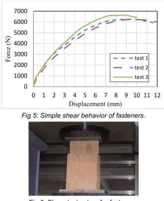
3.2 Load carrying capacity tests for fasteners
Three tests were examined to determine the load carrying capacity of fasteners, double shear timber-to-timber with three pieces connected using two nails per side. The nails are rounded cross-section 2.5 mm of diameter and length 45 mm were used. The mean value of the maximum load for fastener Fv,R,mean was
1.59 KN.
Fig 5: Simple shear behavior of fasteners.
Fig 6: Shear test set up for fasteners.
3.3 Racking tests of cross plank wall
Five walls of large scale timber cross planks were used, each wall of cross planks consists of three layers and the connection of these layers is done using rounded nails of diameter 2.5 mm and 45 mm long. The walls were 250 cm in height, 120 cm in width and 7.5 cm in thick. A horizontal racking load was applied to the top of wall by a hydraulic jack.
3.4 Racking tests of Oriented Strand Board (OSB) panel
Timber frame with oriented strand board was used with height 300 cm, width 121cm and thickness 13.5 cm. The wall was fixed to the floor to avoid sliding, a horizontal load was applied to the top of the panel with the same previous techniques. The wall was consisting of three columns (studs) and OSB3 sheet.
0 20 40 60 80 100 0 2 4 6 8 10 F o rc e (K N ) Displacement (mm) test 1 test 2 test 3 test 4 test 5 0 5 10 15 20 0 1 2 3 4 5 F o rc e (K N ) Displacement (mm) Test1 Test 2 Test 3 Test 4 0 1000 2000 3000 4000 5000 6000 7000 0 1 2 3 4 5 6 7 8 9 10 11 12 F o rc e (N) Displacement (mm) test 1 test 2 test 3
Fig 7: Timber cross plank wall in test.
Fig 8: Force-Displacement behaviour.
Fig 9: OSB panel in test.
Fig 10: Force-Displacement behavior for OSB panel.
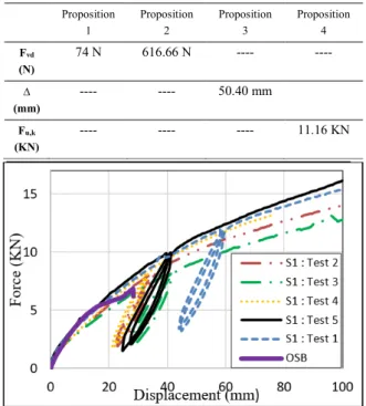
4 CALCULATIONS AND DISCUSION
The lateral load carrying capacity (Fv,RK) for the nails
used in cross plank wall has been calculated according to the Eurocode 5 formulas and it was 616.66 N. The ultimate horizontal force at the top of the wall has calculated based on the proposition 4 and it was 11.16 KN with a top displacement 50.40 mm. considering the factor of safety equal to 1.3 then the design force of the wall will be 11.16/1.3 = 8.58 KN. The internal force on each nail as a proportional of the rotational rigidities and based on the first proposition was Fi = 74 N but
considering to the second assumption of moments equilibrium, the internal force at the nail was 616.66 N.
Tab. 1: assumption values for cross plank wall
Proposition 1 Proposition 2 Proposition 3 Proposition 4 Fvd (N) 74 N 616.66 N ---- ---- ∆ (mm) ---- ---- 50.40 mm Fu,k (KN) ---- ---- ---- 11.16 KN
Fig 11: Comparison between the behavior of cross plank walls and OSB panel.
5 CONCLUSION
The behavior of cross plank walls made from unclassified timber proved a greater resistance and more rigidity than OSB panel due to the huge numbers of internal rotational moments that created in each shear plane in the wall. An analytical model has been created to represent the internal forces on each fastener and calculating the ultimate force on the top of the wall. This wall has a good performance in construction of civil engineering to resist the lateral loads.
6 REFERENCES
[Wei 2012] Wei Y. Loo, Pierre Quenneville, Nawawi Chouw. A numerical study of the seismic behavior of timber shear walls with slips-friction connectors. Engineering Structures (2012) 34 233-243.
[EN 2006] European Standard. Timber structures-test methods- racking strength and stiffness frame wall panels, European Committee for Standardization (2006).
[Johan 2010] Johan Vessby, Erik Serrano, Anders Olsson. Coupled and uncoupled nonlinear elastic finite element models for monotonically loaded sheathing-to-0 1 2 3 4 5 6 7 8 0 5 10 15 20 25 30 F o rc e (k N ) Displacement (mm)
framing joints in timber based shear walls. Engineering Structures. 32 (2010) 3433-3442.
[Kallsner 2009] Kallsner B, Girhammar UA. Analysis of fully anchored light frame timber shear wall elastic model. Mater Struct (2009); 42(3):301-20.
[Natalino 2016] Natalino Gattesco, Ingrid Boem. Stress distribution among sheathing-to-frame nails of timber shear walls related to different base connections:
Experimental tests and numerical modelling.
Construction and Building Materials 122 (2016) 149-162.
[Roberto 2013] Roberto Tomasi, Tiziano Sartori. Mechanical behaviour of connections between wood frame shear walls and foundations under monotonic and cyclic load. Construction and Building Material 44 (2013) 682-690.
[Kozem 2012] E. Kozem Silih, M. Premrov. Influence of openings on horizontal load-carrying capacity of timber-frame wall elements with fibre-plaster sheathing boards. Advances in Engineering Software 43 (2012) 19-26.
[Ozgur 2016] Ozgur Antil, et al. Hysteretic behaviour of timber framed shear wall with openings. Construction and Building Materials 116 (2016) 203-215.
[F. Vieux 2014] F. Vieux-Champagne, et al. Experimental analysis of seismic resistance of timber-framed structures with stones and earth infill. Engineering Structures 69 (2014) 102-115.
[P. Dobrila 2003] P. Dobrila, M. Premrov. Reinforcing methods for composite timber frame-fiberboard wall panels. Engineering Structures 25 (2003) 1369-1376.